Wideband slot antennas for radar applications - University of ...
Wideband slot antennas for radar applications - University of ...
Wideband slot antennas for radar applications - University of ...
- No tags were found...

You also want an ePaper? Increase the reach of your titles
YUMPU automatically turns print PDFs into web optimized ePapers that Google loves.
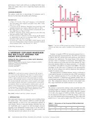
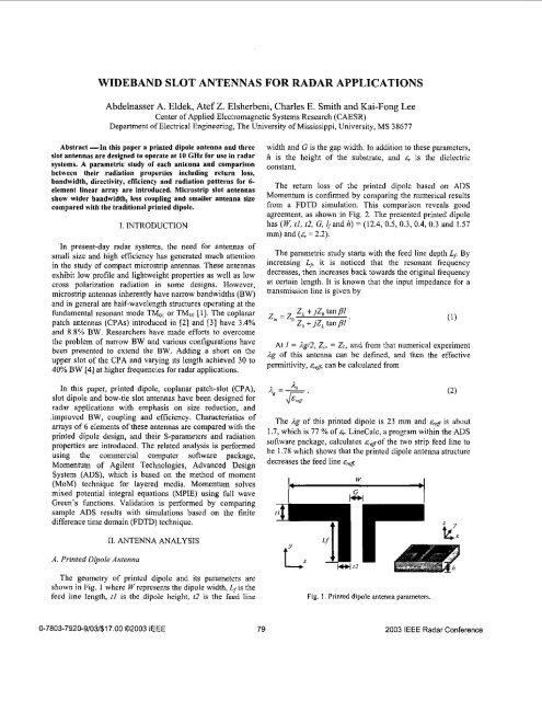
WIDEBAND SLOT ANTENNAS FOR RADAR APPLICATIONSAbdelnasser A. Eldek, Atef Z. Elsherbeni, Charles E. Smith and Kai-Fong LeeCenter <strong>of</strong> Applied Electromagnetic Systems Research (CAESR)Department <strong>of</strong> Electrical Engineering, The <strong>University</strong> <strong>of</strong> Mississippi, <strong>University</strong>, MS 38677Abstract -In this paper a printed dipole antenna and three<strong>slot</strong> <strong>antennas</strong> are designed to operate at 10 GHz <strong>for</strong> use in <strong>radar</strong>systems. A parametric study <strong>of</strong> each antenna and comparisonbetween their radiation properties including return loss,bandwidth, directivity, efficiency and radiation patterns <strong>for</strong> 6-element linear array are introduced. Microstrip <strong>slot</strong> <strong>antennas</strong>show wider bandwidth, less coupling and smaller antenna suecompared with the traditional printed dipole.I. INTRODUCTIONIn present-day <strong>radar</strong> systems, the need <strong>for</strong> <strong>antennas</strong> <strong>of</strong>small size and high efficiency has generated much attentionin the study <strong>of</strong> compact microstrip <strong>antennas</strong>. These <strong>antennas</strong>exhibit low pr<strong>of</strong>ile and lightweight properties as well as lowcross polarization radiation in some designs. However,microstrip <strong>antennas</strong> inherently have narrow bandwidths (BW)and in general are half-wavelength structures operating at thefundamental resonant mode TMoI or TMID [l]. The coplanarpatch <strong>antennas</strong> (CPAs) introduced in [2] and [3] have 3.4%and 8.8% BW. Researchers have made ef<strong>for</strong>ts to overcomethe problem <strong>of</strong> narrow BW and various configurations havebeen presented to extend the BW. Adding a short on theupper <strong>slot</strong> <strong>of</strong> the CPA and varying its length achieved 30 to40% BW [4] at higher frequencies <strong>for</strong> <strong>radar</strong> <strong>applications</strong>.In this paper, printed dipole, coplanar patch-<strong>slot</strong> (CPA),<strong>slot</strong> dipole and bow-tie <strong>slot</strong> <strong>antennas</strong> have been designed <strong>for</strong><strong>radar</strong> <strong>applications</strong> with emphasis on size reduction, and.improved BW, coupling and efficiency. Characteristics <strong>of</strong>arrays <strong>of</strong> 6 elements <strong>of</strong> these <strong>antennas</strong> are compared with theprinted dipole design, and their S-parameters and radiationproperties are introduced. The related analysis is per<strong>for</strong>medusing the commercial computer s<strong>of</strong>tware package,Momentum <strong>of</strong> Agilent Technologies, Advanced DesignSystem (ADS), which is based on the method <strong>of</strong> moment(MOM) technique <strong>for</strong> layered media. Momentum solvesmixed potential integral equations (MPIE) using full waveGreen's functions. Validation is per<strong>for</strong>med by comparingsample ADS results with simulations based on the finitedifference time domain (FDTD) technique.width and G is the gap width. In addition to these parameters,h is the height <strong>of</strong> the substrate, and gr is thc dielectricconstant.The retum loss <strong>of</strong> the printed dipole based on ADSMomentum is confirmed by comparing the numerical resultsfrom a FDTD simulation. This comparison reveals goodagreement, as shown in Fig. 2. The presented printed dipolehas (K tl, 22, G, /,and h) = (12.4, 0.5, 0.3, 0.4, 0.3 and 1.57mm) and (gr = 2.2).The parametric study starts with the feed line depth L/. Byincreasing Lfi it is noticed that the resonant frequencydecreases, then increases back towards the original frequencyat certain length. It is known that the input impedance <strong>for</strong> atransmission line is given byzi, = z,Z, + jZ, tan p/Z, + jZ, tan p/ 'At I = .2g/2, Z, = ZL, and from that numerical experiment.2g <strong>of</strong> this antenna can be defined, and then the effectivepermittivity, can be calculated fromThe Ag <strong>of</strong> this printed dipole is 23 mm and E,~ is about1.7, which is 77 % <strong>of</strong> &,. LineCalc, a program within the ADSs<strong>of</strong>tware package, calculates creJ<strong>of</strong> the two strip feed line tobe 1.78 which shows that the printed dipole antenna structuredecreases the feed line grCfiWA. Printed Dipole Antenna11. ANTENNA ANALYSISThe geometly <strong>of</strong> printed dipole and its parameters areshown in Fig. 1 where Wrepresents the dipole width, L,is thefeed line length, fl is the dipole height, 12 is the feed lineFig. I. Printed dipole antenna parameters0-7803-7920-9/03/$17.00 02003 IEEE 79 2003 IEEE Radar Conference
SI1 IdB)Fig. 2. ADS Momentum and FDTD results <strong>for</strong> the printed dipoleantenna.Fig. 4.f(GHnADS Momentum and FDTD results <strong>for</strong> the <strong>slot</strong> dipoleantenna.Additional parametric study <strong>for</strong> this antenna shows thatincreasing W, h and E, reduces the resonant frequency, andthat tl and the feed line parameters control the return losslevel. Further study shows that the dominant factor in thedesign <strong>of</strong> printed dipoles is W, which traditionally assumed tohe 4 /2. This antenna has more than 12 % BW and 90 %efficiency.8. Slot Dipole AntennaThe <strong>slot</strong> dipole geometry and its parameters are shown inFig. 3 where W represents the dipole width, SI is the <strong>slot</strong>height, L,, is the length <strong>of</strong> the coplanar waveguide (CPW)feed line, and S2 and G are the width and gap width <strong>of</strong> theCPW. In addition to these parameters, h is the height <strong>of</strong> thesubstrate, and E, is the dielectric constant.The <strong>slot</strong> dipole presented in this paper has <strong>for</strong> thefollowing parameters, (W, SI, L,,, S2, G and h), the values(19.3, 1.5, 1.5, 0.25, 1, and 1.57 mm) and E~ =2.2. Figure 4shows a comparison between ADS Momentum and FDTDresults <strong>for</strong> the presented <strong>slot</strong> dipole. This comparison revealsgood agreement and confirms our design procedure usingMomentum.rIWwc: ,--,-Fig. 3. Slot dipole antenna geometry and parameters.Lcpw behaves like L/ in the printed dipole, and .2, and ~,*fare calculated by the same procedure. The calculated 4 <strong>of</strong> the<strong>slot</strong> dipole is found to be 23.5 mm and 1.63 (74% <strong>of</strong>.$, respectively. The ~,g <strong>of</strong> the CPW feed line based onLineCalc calculations is 1.576, which shows that the <strong>slot</strong>dipole antenna structure increases the feed line E,@,By observing the influence <strong>of</strong> various parameters on theantenna per<strong>for</strong>mance, it is found that increasing W, SI, h andE, decreases the resonant frequency, and SI and the feed lineparameters control the return loss level. Further study showsthat the total <strong>slot</strong> length, calculated at the centerline <strong>of</strong> the<strong>slot</strong>, is ahout LE and W is ahout 0.82 4. This antenna canprovide more that 21 % BW and 80 %efficiency.C. Coplanar Patch-Slot AntennaThe CPA antenna consists <strong>of</strong> a rectangular patchsurrounded by a non-uni<strong>for</strong>m width <strong>slot</strong>. Antenna geometryand parameters are shown in Fig. 5, where W represents thepatch width, L is the patch length, SI, S2 and S3 are thewidths <strong>of</strong> the upper, left-right, and lower <strong>slot</strong>s, respectively,S4, Si,and Lcpw are the gap width, feed line width and thelength <strong>of</strong> the CPW, h is the height <strong>of</strong> the substrate and isthe dielectric constant. Figure 6 shows a comparison betweenADS and FDTD results <strong>for</strong> the presented CPA that has (K L.SI , S2, S3. 5’4, S5, L,, and h) = (12.4, 2, 0.5,0.25,0.5,0.25,0.75, 1.5and1.57mm)and~,=2.2.In this antenna, Lcpw behaves like L/ in the printed dipoleantenna design, and ,IK and &fare calculated, using the sameprocedure used <strong>for</strong> the dipole, to be 23.5mm and 1.54 (70 %E~), respectively. LineCalc calculation <strong>of</strong> Emf<strong>of</strong> the CPW feedline is 1.58, which shows that the CPA antenna decreases thefeed line80 2003 IEEE Radar Conference
By observing the influence <strong>of</strong> various parameters on theantenna per<strong>for</strong>mance it is found that increasing W, L, h, E,, SIand S2 and decreasing S3 reduce the resonant frequency. TheCPW feed line parameters control the retum loss level.Although the effect <strong>of</strong> all these parameters is clear onh, it isnot clear which one parameter can primarily increase the BW<strong>of</strong> the antenna. In CPA design, the dominant factors are W, Land the total <strong>slot</strong> length (Ltotal), calculated at the centerline<strong>of</strong> the <strong>slot</strong>, whereLtotal= 2(w+L+Lcpw+s2+s3)+sI-s4-s5. (3)By studying the given design at various center frequencies,it is clear that W is about 0.5& and the Ltoral is about 1.5&At the same time L is about O.l& In general Ltotal controlsthe resonant frequency while patch dimensions and <strong>slot</strong>widths control the level <strong>of</strong> return loss and the resulting BW.This antenna can give more that 17 % BW and 80 %efficiency.D. Bow-Tie Slot AntennaThe geometry <strong>of</strong> the bow-tie <strong>slot</strong> antenna and itsparameters are shown in Fig. 7 where W, represents thewidth, L, is the feed line length, L,, L2, L,, L4 and W, definethe bow shape, and SI and S, define the feed line parameters.In addition to these parameters, h is the height <strong>of</strong> thesubstrate, and E, is the dielectric constant. The presented bowtiedesign has the parameters ( WI, W,, L,, L2, L3, L4, L, s,,SI, and h) being set equal to (22.9, 8.7, 3.5, 20.75, 19.45,7.35, 18.5, 0.25, 3, and 1.57 nun) and &,=2.2. Figure 8 showsa comparison between ADS Momentum and FDTD results<strong>for</strong> the presented bow-tie <strong>slot</strong> antenna. Although a stair casegeometry is used in FDTD to define the bow-tie geometry,and only one cell is used in the feed line <strong>slot</strong> due to memoryrestrictions, the comparison reveals acceptable agreement,which confirms our design procedure using Momentum.W,Fig. 5. Coplanar patch antenna geometly and parameters.Fig. 7. Bow-tie <strong>slot</strong> antenna geometly and parameters.SI1 (dB)0, Return Loss (dB)0, I--- FDTD jI-ADS If (GHz)Fig. 6. Comparison between the ADS Momenhlm and FDTDresults <strong>for</strong> the presented CPA.Fig. 8. Comparison between the ADS Mamentnm and FDTDresults <strong>for</strong> the presented Bow-tie <strong>slot</strong> antenna.812003 IEEE Radar Conference
....9 10f (GHz)11 12(d)-20 Is2 1-20S51-701-1 -.- CPA '.... .......--2030.. ... . * I d ? % . ... 1 .........-- ; I ---_ Icc ..... .+ .*.-.-.-.-1-.-. -+--40.. .*. ... .........., -.-. I--.>,. .,... I, *....* --I-.... ....8-20,S61I- , -.Slot dipoleI .CPABow-tie .......9 f (GHzl 10 11 12Fig. 11. Rehlm loss and coupling between elements <strong>of</strong> h-element array module <strong>for</strong> printed dipole, <strong>slot</strong> dipole, CPA andbow-tie <strong>slot</strong> antenna with distance between elements equals to 20.8, 3, 8.5, and 4 mm, respectively. (a) SII, (b)S2l,(c)S31 (d)S41,(e)S51 and(f)S61.83 2003 IEEE Radar Conference
ttSlot dipoletCPABow-tieFig. 12. Radiation pattern in x-y plane..-Printed dipole Slot dipoleBow-tie(a) x-z planewPrinted diwle$6Slot diooleII.3"S"CPA Bow-tie *IFig. 14. Total 3D radiation panem.IV. CONCLUSIONSIn this paper a printed dipole antenna and three microstrip<strong>slot</strong> <strong>antennas</strong> operating at IO GHz in the X-band (8-12 GHz),are presented. Parametric studies <strong>for</strong> each antenna showingthe effect <strong>of</strong> each geometric parameter and <strong>antennas</strong>'dimensions in terms <strong>of</strong> h8 are presented. Slot <strong>antennas</strong>achieve better BW that reaches 40% over the entire band. Inaddition to smaller and less than -24 dB coupling betweenelements is obtained <strong>for</strong> the 6-element arrays. The efficiency<strong>of</strong> the <strong>slot</strong> <strong>antennas</strong> is near 80% but less than printed dipole.The cross-polarization level is less than -27 dB in the x-zplane and 4 0 dB in the y-z plane. All <strong>antennas</strong> show goodradiation pattern stability over the entire band <strong>of</strong> operation.REFERENCES[I] K-L Wong, "Compact and Broadband MicrostripAntennas", John Wiley andsons, New York, NY, 2002.[2] K. Li, C. H. Cheng, T. Matsuni and M. Izutsu, "Coplanarpatch <strong>antennas</strong>: principal, simulation and experiment,"Proc. Antennas Propagat. Soc. Int. Symp., Boston, MA,July 2001, vol. 3, pp. 402-405.[3] K. F. Tong, K. Li, T. Matsuni and M. Izutsu, "<strong>Wideband</strong>coplanar waveguide fed coplanar patch antennq" Proc.Antennas Propagat. Soc. Int. sy"., Boston, MA, July2001, vol. 3, pp. 406-409.[4] A. Z. Elsherbeni, Abdelnasser A. Eldek, B. N. Baker, C.E. Smith and K-F Lee, "<strong>Wideband</strong> coplanar patch-<strong>slot</strong><strong>antennas</strong> <strong>for</strong> <strong>radar</strong> <strong>applications</strong>," Proc. AntennasPropagat. Soc. Inl. Symp., Houston, TX, June 2002, vol.2, pp. 436-439.(b) y-z planeFig. 13. Radiation panem in x-z and y-z planes84 2003 IEEE Radar Conference