OBLIQUE INCIDENCE PLANE WAVE SCATTERING FROM AN ...
OBLIQUE INCIDENCE PLANE WAVE SCATTERING FROM AN ...
OBLIQUE INCIDENCE PLANE WAVE SCATTERING FROM AN ...

Create successful ePaper yourself
Turn your PDF publications into a flip-book with our unique Google optimized e-Paper software.
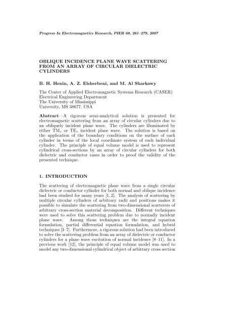
Progress In Electromagnetics Research, PIER 68, 261–279, 2007<strong>OBLIQUE</strong> <strong>INCIDENCE</strong> <strong>PL<strong>AN</strong>E</strong> <strong>WAVE</strong> <strong>SCATTERING</strong><strong>FROM</strong> <strong>AN</strong> ARRAY OF CIRCULAR DIELECTRICCYLINDERSB. H. Henin, A. Z. Elsherbeni, and M. Al SharkawyThe Center of Applied Electromagnetic Systems Research (CASER)Electrical Engineering DepartmentThe University of MississippiUniversity, MS 38677, USAAbstract—A rigorous semi-analytical solution is presented forelectromagnetic scattering from an array of circular cylinders due toan obliquely incident plane wave. The cylinders are illuminated byeither TM z or TE z incident plane wave. The solution is based onthe application of the boundary conditions on the surface of eachcylinder in terms of the local coordinate system of each individualcylinder. The principle of equal volume model is used to representcylindrical cross-sections by an array of circular cylinders for bothdielectric and conductor cases in order to proof the validity of thepresented technique.1. INTRODUCTIONThe scattering of electromagnetic plane wave from a single circulardielectric or conductor cylinder for both normal and oblique incidencehad been studied for many years [1, 2]. The analysis of scattering bymultiple circular cylinders of arbitrary radii and positions makes itpossible to simulate the scattering from two-dimensional scatterers ofarbitrary cross-section material decomposition. Different techniqueswere used to solve this scattering problem due to normally incidentplane wave. Among those techniques are the integral equationformulation, partial differential equation formulation, and hybridtechniques [3–7]. Furthermore, a rigorous solution had been introducedto solve the scattering problem from an array of dielectric or conductorcylinders for a plane wave excitation of normal incidence [8–11]. In aprevious work [12], the principle of equal volume model was used tomodel any two-dimensional cylindrical object of arbitrary cross section
262 Henin, Elsherbeni, and Al Sharkawyby an array of circular cylinders. The authors provided a detailedderivation for the problem of scattering of a plane wave from an arrayof parallel circular cylinders in case of normal incidence. The solution isbased on applying the continuity of the tangential electric and magneticfields on the surface of each cylinder. In [13, 14], the same techniquewas used for an array of circular bianisotropic cylinders in the case ofnormal incidence.For many practical applications, the excitation of plane wave isusually not at normal incident with respect to the scatterer. Therefore,in order to provide accurate assessment of the scattering properties ofobjects, one has to consider oblique incident conditions. The obliquelyincident plane wave on the surface of one or two bianisotropic cylinderswas considered before [15–17]. In [18], a linear array of bianisotropiccylinders was considered with constant distances between the cylinders.Previous investigations with oblique incident plane wave on multiplecylinders exhibit many limitations. Either the cylinders configurationsare confined to linear array, or the solution technique is not proven totackle practical configurations.In this paper, the scattering of an obliquely incident plane waveon an array of parallel dielectric circular cylinders of arbitrary radiiand positions is considered. The analysis begins by representing eachfield component by an infinite series of cylindrical harmonic functionswith unknown coefficients. Then equations based on the boundaryconditions applied on the surface of each cylinder are used to deducethe values of the unknown coefficients. The detailed derivation for theTM z excitation is given, and the extension to TE z is outlined.To prove the validity of the results, some numerical examples aregiven to illustrate the principle of equal volume model in the caseof an obliquely incident plane wave. Both cases of TM z and TE zare considered for conductor, dielectric cylinders, or combinations.Furthermore, the near field is calculated to prove the validity of theboundary conditions on the surface of any cylinder.2. FORMULATIONWithout losing generality, the scattering from an obliquely incidentE-polarized TM z plane wave from an array of M cylinders parallel toeach other and to the z-axis of a global coordinate system (ρ, φ, z) isconsidered. The incident electric field of a plane wave on cylinder “i”
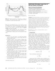
Progress In Electromagnetics Research, PIER 68, 2007263is expressed in the (ρ i ,φ i ,z), cylindrical coordinate system for e jωt asEz inci(ρ i ,φ i ,z) = E 0e ′ jk 0z cos θ 0e jk 0ρ i sin θ 0 cos(φ i −φ 0 ) e jk 0ρ ′ i sin θ 0 cos(φ ′ i −φ 0)= E 0e ′ jk 0z cos θ 0e jk 0ρ ′ i sin θ 0 cos(φ ′ i −φ 0)∞∑× j n J n (k 0 ρ i sin θ 0 ) e jn(φ i−φ 0 ) , (1)−∞where E 0 ′ = E 0 sin θ 0 , θ 0 is the oblique incident angle as shown in Fig. 1and E 0 is the amplitude of the incident electric field component. Theparameter k 0 is the free space wave number, φ 0 is the angle of incidenceof the plane wave in the x-y plane with respect to the positive x-axis,and the J n (ξ) is the Bessel function of order n and argument ξ. Thesecond expression of the incident field component is in terms of thecylindrical coordinate of the ith cylinder, whose center is located at(ρ ′ i ,φ′ i ,z) of the global coordinate (ρ, φ, z).zincEφθ 00IncidentwaveyxFigure 1. The parameters describing the obliquely incident E-polarized plane wave on a simple cylinder.The resulting z component of the scattered electric field from theith cylinder and the transmitted z component of the field inside thecylinder material can be expressed, respectively, asE s z(ρ i ,φ i ,z)=E ′ 0e jk 0z cos θ 0∞ ∑−∞A in H (2)n (k 0 ρ i sin θ 0 ) e jn(φ i−φ 0 ) , (2)∞ (∑Ez d (ρ i ,φ i ,z)=E 0e ′ jk 0z cos θ 0√kd2 B in J n k 0 ρ ik02 −cos 2 θ 0)e jn(φ i−φ 0 ) , (3)−∞
Progress In Electromagnetics Research, PIER 68, 2007265cylinder “i” can be expressed, respectively, asH s φ i(ρ i ,φ i ,z) = E ′ 0G k 0jη 0 λ 0−E ′ 0G hλ 2 0 ρ ik dHφ d i(ρ i ,φ i ,z) = E 0G′ jη d λ d−E ′ 0G hλ 2 d ρ i∞ ∑−∞∞∑−∞∑∞−∞A in H (2)′n (λ 0 ρ i ) e jn(φ i−φ 0 )nC in H (2)n (λ 0 ρ i ) e jn(φ i−φ 0 ) , (8)B in J ′ n (λ d ρ i ) e jn(φ i−φ 0 )∞∑nD in J n (λ d ρ i ) e jn(φ i−φ 0 ) , (9)−∞where h = k 0 cos θ 0 , λ 0 = k 0 sin θ 0 , G = e jk 0z cos θ 0√, k d = k 0 µdr ε dr ,√λ d = kd 2 − k2 0 cos2 θ 0 , η 0 = √ √µ 0 /ε 0 , and η d = η 0 µdr /ε dr .In the same manner, the φ components of the electric field can bederived using Maxwell’s equations as followE φ = 1 ( ∂Hρjωε ∂z− ∂H )z,∂ρ(where H ρ = −1 1 ∂E zjωµ ρ ∂φ− ∂E φ∂z).Thus the φ component of the incident electric field on cylinder “i”takes the formE incφ i(ρ i ,φ i ,z) = −hE′ 0λ 2 0 ρ e jk 0z cos θ 0e jk 0ρ ′ i sin θ 0 cos(φ ′ i −φ 0)i(10)∞∑nj n J n (λ 0 ρ i ) e jn(φ i−φ 0 ) ,−∞while the φ components of the scattered electric field and the electricfield transmitted inside cylinder “i” can be expressed, respectively, asE s φ i(ρ i ,φ i ,z) = −E ′ 0G hλ 2 0 ρ i−E ′ 0G η 0k 0jλ 0∞∑−∞∑∞−∞nA in H (2)n (λ 0 ρ i ) e jn(φ i−φ 0 )C in H (2)′n (λ 0 ρ i ) e jn(φ i−φ 0 ) , (11)
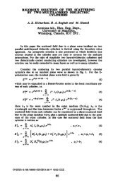
266 Henin, Elsherbeni, and Al Sharkawyy gx gy iyρ'gφg'φ'ixρ'id igφigx iFigure 2. The cross-sectional geometry of the cylinders in the x-yplane.E d φ i(ρ i ,φ i ,z) = −E ′ 0G hρ i λ 2 d−E ′ 0G k dη djλ d∞∑nB in J n (λ d ρ i ) e jn(φ i−φ 0 )−∞∑∞−∞D in J n (λ d ρ i ) e jn(φ i−φ 0 ) , (12)The expressions in equations (2)–(5), (8)–(9), and (11)–(12)indicate that both the electric and magnetic field components arebased on the local coordinates (ρ i ,φ i ,z) of cylinder “i”. However, theinteraction between the M cylinders in terms of multiple scatteredfields will require a representation of the scattered field from onecylinder in terms of the local coordinates of another as shown inFig. 2. Therefore, the addition theorem of Bessel and Hankel functionsare used to transfer the scattered field components from one set ofcoordinates to another. As an example the scattered fields from thegth cylinder in terms of the ith cylinder are presented by [11, 12]H (2) (λ 0 ρ g ) e jmφg= ∑ mJ m (λ 0 ρ i ) H (2)m−n (λ 0d ig ) e jmφ ie −j(m−n)φ ig(13)d ig = ρ ′ 2i + ρ ′ 2g − 2ρ ′ iρ ′ g cos ( φ ′ i − φ ′ g),
Progress In Electromagnetics Research, PIER 68, 2007267⎧ (ρ′⎪⎨cos −1 i cos (φ ′ i ) − ρ′ g cos ( φ ′ )gρ ′ id sin(φ′ i ) ≥ ρ′ g sin ( φ ′ )gigφ ig = (ρ′⎪⎩ − cos −1 i cos (φ ′ i ) − ρ′ g cos ( φ ′ )gρ ′ id sin(φ′ i )
268 Henin, Elsherbeni, and Al SharkawywhereV 1 = hP (i 1lj l J la i λ 2 − 1 )dλ 2 , (21)0V 2 = P i j l−1 (kdη d λ dJ ld J l − k 0η 0 λ 0J ′ l), (22)S 1 =0i = g,l≠ n[ hlHl=λ 2 0 a − hlH ]li λ 2 d a i = g,l= n (23)i[ hlJl=λ 2 0 a − hlJ ]lg λ 2 d a H ln i ≠ g,iandS 2 =0==[k0H l ′ jη 0 λ −0[k0J l ′ jλ −0k ]dH l J ldjη d λ di = g,l≠ ni = g,l= n (24)k ]dJ l J ld H ln i ≠ g,jη d λ dR 1 =0i = g,l≠ n[k0 η 0= H l ′ jλ − k ]dη dH l J ld i = g,l= n (25)0 jλ d[k0 η 0= J l ′ jλ − k ]dη dJ l J ld H ln i ≠ g,0 jλ dwhileR 2 =0i = g,l≠ n[ hlHl= −λ 2 0 a − hlH ]li λ 2 d a i = g,l= n (26)i[ hlJl= −λ 2 0 a − hlJ ]lg λ 2 d a H ln i ≠ g,iJ l = J l (λ 0 a i )J l (λ d a i ) ,J′ l = J l ′ (λ 0a i )J l (λ d a i ) ,J ld = J l ′ (λ da i )J l (λ d a i ) ,H l = H(2) l(λ 0 a i )J l (λ d a i ) ,H l ′ = H(2)′ l(λ 0 a i ),H ln = H (2)J l (λ d a i )l−n (λ 0d ig ) e −j(l−n)(φ ig−φ 0 ) ,P i = e jk 0ρ ′ i cos(φ′ i −φ 0) sin(θ 0 )
Progress In Electromagnetics Research, PIER 68, 2007269where the integers n, l =0, ±1, ±2,... ,±N i and i, g =0, 1, 2,... ,M.Theoretically, N i is an integer which is equal to infinity; however, it isrelated to the radius “a i ” of cylinder “i”, and type of the ith cylinderby the relation N i ≈ (1+2k i a i ). Equations (19) and (20) are then castinto a matrix form such as[ ] [ ][ ]V1 S1 R= 1 A. (27)V 2 S 2 R 2 CThe solution of the above truncated matrix equation yields theunknown scattering coefficients A in and C in .For the case of incident H-polarized TE z plane wave, the incidentmagnetic field is expressed in the (ρ i ,φ i ,z), cylindrical coordinatesystem as,Hz inci(ρ i ,φ i ,z) = H0 ∗ e jk 0z cos θ 0e jk 0ρ ′ i sin θ 0 cos(φ ′ i −φ 0)∞∑j n J n (k 0 ρ i sin θ 0 ) e jn(φ i−φ 0 ) , (28)−∞where H0 ∗ = H 0 sin θ 0 . One can easily express the field components foraTE z case, be applying the same procedure used to derive the fieldsfrom a TM z illumination, where the z component of the scatteredfield and the transmitted z component of the field inside the cylindermaterial have the same form as in equation (2) to equation (5). Theonly difference in the final expressions is in equations (21) and (22),where these two equations are to be replaced by,(V 1 = P i j l−1 kd η dJ ld J l − k )0η 0J l′ , (29)λ d λ 0V 2 = hP (i 1lj l J la i λ 2 − 1 )0 λ 2 . (30)dTherefore the numerical simulation of TE z polarization can be easilyobtained from the TM z simulation code.3. NUMERICAL RESULTSIn this section, sample numerical results are presented to proof thevalidity of the developed formulation for computing the radar crosssection(RCS) of an array of cylinders excited by an obliquely incidentTM z or TE z plane wave. For all configurations presented in this paper,the incident wave frequency was set to 300 MHz, and the echo width
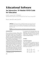
270 Henin, Elsherbeni, and Al Sharkawyis defined as(σ 2D = 10 loglimρ→∞[2πρ |Es z| 2|E i z| 2 ]). (31)0-10TEσ2D / λ (dB)-20-30TM-40This papero Reference [1]-500 60 120 180 240 300 360φ (degrees)Figure 3. The echo width of a single cylinder of radius a =0.1λ,ε r =4,θ i = 45, φ i =0.Figure 3represents the RCS calculated from a dielectric cylinderof radius a =0.1λ, having relative permittivity ε r = 4, with incidentangel θ i = 45 and φ i = 0. Both TM z and TE z plane waveexcitations are considered. The results generated using the presentedboundary value solution (BVS) technique are compared to the RCSdata calculated from [1]. It is clear from the figure that the twosolutions are in complete agreement for both TM z and TE z plane waveexcitation.In order to prove the validity of the above calculations for multiplecylinders, the principle of equal volume model can be used to representone single cylinder by an array of cylinders. According to this principle,the scattered field from one cylinder is expected to be the same as thatof an array of cylinders having the total cross section area equal to thecross section area of the cylinder, and having the same outer shape. InFig. 4, 91 non-intersected cylinders of radius 0.04λ are used to simulatea cylinder of radius 0.4λ. The dielectric constant of the cylinders ischosen to be greater than that of the single cylinder to achieve equaleffective area, assuming that the effective area is the product of thecross section area and the relative permittivity of the cylinder.
Progress In Electromagnetics Research, PIER 68, 20072710.40.20-0.2-0.4-0.4 -0.2 0 0.2 0.4Figure 4. The relative position of an array 91 cylinders.1510one cylinder91 cylinders52D / λ (dB)σ0-5-10-15-200 60 120 180 240 300 360(degrees)φFigure 5. The echo width results of a TM z plane wave incident onone cylinder of radius 0.4λ, ε r =4,θ i = 45, φ i = 0, represented by 91non-intersected cylinders.Figure 5 shows the echo width calculated from one cylinder ofradius 0.4λ, having relative permittivity ε r = 4, and excited by a TM zplane wave with incident angel θ i = 45 and φ i = 0. The computed echowidth is obtained using the expressions provided in [1], and comparedwith the echo width results generated using an array of cylinders. InFig. 6, another comparison is presented for the same cylinder definitionbut at different incident angel θ 0 =75,φ 0 =0.
272 Henin, Elsherbeni, and Al Sharkawy1510one cylinder91 cylinders52D / λ (dB)σ0-5-10-15-200 60 120 180 240 300 360(degrees)φFigure 6. The echo width results of a TM z plane wave incident onone cylinder of radius 0.4λ, ε r =4,θ i = 75, φ i = 0, represented by 91cylinders.1510one cylinder91 cylinders2D / λ (dB)σ50-5-100 60 120 180 240 300 360(degrees)φFigure 7. The echo width results of a TE z plane wave incident onone cylinder of radius 0.4λ, ε r =4,θ i = 45, φ i = 0, represented by 91cylinders.Figure 7 shows the echo width calculated from one cylinder ofradius 0.4λ, having relative permittivity ε r = 4, and excited by a TE zplane wave with incident angel θ i = 45 and φ i = 0. In this case,the results are not completely equivalent due to the presence of the φcomponent of the electric field. The field is affected by the shape of
Progress In Electromagnetics Research, PIER 68, 20072731614One cylinder20 cylinders122D / (dB)λσ1086420 60 120 180 240 300 360(degrees)φFigure 8. The echo width results of a TM z plane wave incident ona perfectly conducting cylinder of radius a =1λ for obliquely incidentangle θ i = 45, φ i =0.15105One cylinder20 cylinders30 cylinders2D / (dB)λσ0-5-10-15-200 60 120 180 240 300 360(degrees)φFigure 9. The echo width results of a TE z plane wave incident on aperfectly conducting cylinder of radius a =1λ for obliquely incidentangle θ i = 45, φ i =0.
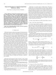
274 Henin, Elsherbeni, and Al Sharkawyzθ iφiincEy21.51x(a)Incident fieldScattered fieldInside fieldIncident + ScatteredE z0.50-0.50 60 120 180 240 300 360φ(degrees)1.5(b)10.5H z0Incident field-0.5 Scatte red fieldInside fieldIncident + Scattered-10 60 120 180 240 300 360φ (degrees)(c)Figure 10. Near field components of three parallel cylinders excited byan incident plane wave at θ i =30,φ i = 0. (a) The arrangement of thecylinders, (b) Continuity of the E z for TM z excitation, (c) Continuityof the H z for TE z excitation.
Progress In Electromagnetics Research, PIER 68, 2007275the outer surface of the array of cylinders which is not as smooth asit is in the one cylinder case. However, the agreement is acceptable tovalidate the TE z developed formulation.Figure 8 shows the echo width calculated from one conductingcylinder of radius 1λ, where the cylinder is excited by a TM z planewave with incident angel θ i = 45 and φ i = 0. The computed echo widthis compared with that of an array of 20 perfectly conducting cylindersof radius a =0.1λ, and all the cylinders are uniformly located on thecircumference of a circle of radius a =0.9λ. The results show excellent1.51.71.51.811.61.511.61.40.51.40.51.2y 0-0.5-11.31.21.110.9y 0-0.5-110.80.60.4-1.5-1 0 1x0.8-1.5-1 0 1x0.2(a)(b)1.5211.81.60.51.4y01.21-0.5-1-1.5-1 0 1x0.80.60.40.2(c)Figure 11. The near field distribution of a TM z plane wave incidenton array of three cylinders at incident angle. (a) θ i =30,φ i = 0, (b)θ i = 60, φ i = 0, (c) θ i = 90, φ i =0.
276 Henin, Elsherbeni, and Al Sharkawy1.510.51. 81. 61. 41.510.51.41.31.2y01. 2y01.1-0.51-0.51-10. 8-10.9-1.5-1 0 1x0. 6-1.5-1 0 1x0.8(a)(b)1.511. 81. 60.51. 4y01. 2-0.51-10. 8-1.5-1 0 1x(c)0. 6Figure 12. The near field distribution of a TE z plane wave incidenton array of three cylinders at incident angle. (a) θ i =30,φ i = 0, (b)θ i = 60, φ i = 0, (c) θ i = 90, φ i =0.agreement between both curves, which indicates the validity of usingthis method to model any perfectly conducting object by an array ofcircular cylinders. For the case of TE z excitation, Fig. 9 shows thatthe result is not in complete agreement for an array of 20 cylinders dueto the effect of the φ component of the electric field as explained in theprevious paragraph. The results can be improved by using an array of30 cylinders as shown in the same figure.As another method to check the validity of this technique andits accuracy, specially in near field region, the scattering coefficientsA in and C in can be used to deduce the coefficients values of thetransmitted field inside the cylinders material B in and D in . Then,
Progress In Electromagnetics Research, PIER 68, 20072 7the numerical values of these four coefficients are used to check thevalidity of boundary equations from equation (15) to equation (18).For simplicity, three cylinders of radius 0.1λ are used. The cylindersare placed symmetry around the x axis with the center of all cylinderslocated on the y axis, and the distance between the centers is 0.7λ.Fig. 10 shows the numerical value of the transmitted field inside thefirst cylinder compared with the summation of the incident field andthe scattered fields form all cylinders on the surface of this cylinder.In Fig. 10(b), the continuity of the H z components in the case of TE zexcitation are considered, and in Fig. 10(c) the continuity of the E zcomponent in the case of TM z excitation are considered. Both figuresare plotted for incident angle θ i =30,φ i =0.Figure 11 shows the near field distribution resulting from theincidence of a TM z polarized plane wave on an array of three cylinders.The cylinders are placed symmetry around the x axis with the centerof the three cylinders located on the y axis, the radius of each cylinderis 0.1λ and the distance between the centers is 0.7λ. The graph showsthe numerical value of the transmitted field inside the cylinders andthe total field outside the cylinders for three different incident anglesθ i = 30, 60, and 90. In Fig. 12, the near field distribution is plottedfor the case of TE z excitation for the same configuration.4. CONCLUSIONSThe analyses of an obliquely incident plane wave scattering froman array of parallel circular cylinders is derived for both TM z , andTE z polarizations. The derivation is based on the application of theboundary conditions on the surface of each cylinder. This solutionis valid for both dielectric and conductor cylinders, and can be usedto study of electromagnetic interaction with any two-dimensionalscattering object that can be constructed from an array of parallelcircular cylinders. Two different methods are presented to check thevalidity of this technique. First, the principle of equal volume modelis used to represent one cylinder by an array of circular cylinders andsample numerical results are given to compare the known echo widthof the scattered field from one cylinder to that of an array of circularcylinders. Second, the near field is calculated to prove the validity ofthe boundary conditions on the surface of each cylinder. The results inboth cases show excellent agreement between the calculated field andthe known results from pervious work for special cases. The presentedscattering technique can be extended for other types of cylinders.
278 Henin, Elsherbeni, and Al SharkawyREFERENCES1. Wait, J. R., “Scattering of a plane wave from a circular dielectriccylinder at oblique incidence,” Can. J. Phys., Vol. 33, 189–195,1955.2. Balanis, C. A., Advanced Engineering Electromagnetics, Wiley,New York, 1989.3. Mei, K. K. and J. Van Bladel, “Scattering by perfectly conductingrectangular cylinder,” IEEE Trans. Antennas Propagat., Vol. AP-11, 185–192, 1963.4. Richmond, J. H., “Scattering by a dielectric cylinder of arbitrarycross-section shape,” IEEE Trans. Antennas Propagat., Vol. AP-13, 334–341, 1965.5. Richmond, J. H., “TE-wave scattering by a dielectric cylinder ofarbitrary cross-section shape,” IEEE Trans. Antennas Propagat.,Vol. AP-14, 460–464, 1966.6. Wu, T. K. and L. L. Tsai, “Scattering by arbitrary crosssectioned layerd lossy dielectric cylinders,” IEEE Trans. AntennasPropagat., Vol. AP-25, 518–524, 1977.7. Jin, J. M. and V. V. Liepa, “Application of hybrid finite elementmethod to electromagnetic scattering from coated cylinders,”IEEE Trans. Antennas Propagat., Vol. 36, 50–54, 1988.8. Young, J. W. and J. C. Bertrand, “Multiple scattering by twocylinders,” J. Acoust. Soc. of Amer., Vol. 58, 1190–1195, 1975.9. Ragheb, H. A. and M. Hamid, “Scattering by N parallelconducting circular cylinders,” Int. J. Electron., Vol. 59, 407–421,Jan. 1985.10. Elsherbeni, A. Z. and M. Hamid, “Scattering by parallelconducting circular cylinders,” IEEE Trans. Antennas Propagat.,Vol. AP-35, 355–358, 1987.11. Elsherbeni, A. Z., “A comparative study of two-dimensionalmultiple scattering techniques,” Radio Sci., Vol. 29, No. 4, 1023–1033, July–Aug. 1994.12. Elsherbeni, A. Z. and A. Kishk, “Modeling of cylindrical objectsby circular cylinders,” IEEE Trans. Antennas Propagat., Vol. 40,96–99, Jan. 1992.13. Yin, W. Y. and L. W. Li, “Multiple scattering from gyrotropicbianisotropic cylinders of arbitrary cross sections using themodeling technique,” Phys. Rev. E, Vol. 60, No. 1, 918–925, 1999.14. Yin, W. Y., L. W. Li, and M. S. Leong, “Scattering from multiplebianisotropic cylinders and their modeling of cylindrical objects of
Progress In Electromagnetics Research, PIER 68, 2007279arbitrary cross-section,” Progress In Elecgtromagnetics Research,PIER 27, 159–184, 2000.15. Jakoby, B., “Scattering of obliquely incident waves by animpedance cylinder with inhomogeneous bianisotropic coating,”IEEE Trans. Antennas Propagat., Vol. 45, No. 4, 648–655, April1997.16. Yousif, H. A. and S. Kohler, “Scattering by two penetrablecylinders at oblique incidence. I. The analytical solution,” J. Opt.Soc. Am. Ser. A, Vol. 5, No. 7, 1085–1096, 1988.17. Yousif, H. A. and S. Kohler, “Scattering by two penetrablecylinders at oblique incidence. II. Numerical examoles,” J. Opt.Soc. Am. Ser. A, Vol. 5, No. 7, 1097–1104, 1988.18. Yin, W., “Scattering by a linear array of uniaxial bianisotropicchiral cylinders,” Microwave Opt. Technol. Lett., Vol. 12, No. 5,287–295, 1996.