
You also want an ePaper? Increase the reach of your titles
YUMPU automatically turns print PDFs into web optimized ePapers that Google loves.
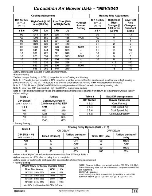
DIP Switch(OFF = 0ON = 1)Circulation Air Blower Data - *9MVX040Cooling AdjustmentHigh Cool @ .50in wc(125 Pa)Low Cool (80%of High Cool)** AdjustJumperSettingDIP Switch(OFF = 0ON = 1)5&6 CFM L/s CFM L/s 3&4Heating Rise AdjustmentHigh HeatRiseChange @0.20 in wc(50 Pa)Low HeatRiseChange atResultantStatic00 1244 587 995 470 + 00 - 3 -- 3*00 1206 569 965 455 *NOM *00 0 000 1126 531 901 425 - 00 4 401 1109 523 887 419 + 01 2 201 1032 487 826 390 NOM 01 6 601 941 444 753 355 - 01 13 1010 901 425 721 340 + 10 0 -- 110 828 391 662 313 NOM 10 3 310 757 357 606 286 - 10 8 711 705 333 564 266 + 11 -- 12 -- 1311 633 299 506 239 NOM 11 -- 10 -- 1011 556 262 445 210 - 11 -- 8 -- 8Airflow performance includes 1” washable filter media.*Factory Setting**Adjust Jumper Setting (+, NOM, --) is applied to both Cooling <strong>and</strong> HeatingNote 1: HP Mode Jumper provides a 10% reduction in airflow when in Comfort position <strong>and</strong> a call for low or high cooling ispresent with the ”O” line off. This feature is to provide lower airflow for running in HP Heating Mode if desirable.Note 2: DEHUM mode (24VAC on DEHUM terminal) provides a 20% airflow reduction during cooling calls.Note 3: Low Heat ESP is a result of High Heat ESP (-- is decrease in rise).Note 4: High <strong>and</strong> low heat rise values are approximate air temperature change from return air temperature when at factorydefault settings.Table 2AirflowTable 3 SW2 DIP AssignmentsDIP Switch(OFF = 0 / ON = 1)Continuous Fan @0.10 in wc (25 Pa) ESP1&2 CFM L/s*00 592 27901 1021 48210 1346 63511 1346 635* Factory SettingTable 4DIP SW2 - 7/8(OFF = 0 / ON = 1)Timed ON (sec)DIP SwitchBlower Parameter1&2 Cont Fan Adj3&4 Heat Speed Adj5&6 Cool Speed Adj7&8 Cool On/Off DelayCooling Delay Options (SW2 - 7, 8)ON DELAYOFF DELAYAirflow during ondelayTimer OFF (sec)Airflow during offdelay*00 5 OFF 90 100%01 5 OFF 0 OFF10 30 50% 30 100%11 30 50% 180 50%Airflow % is of High Cool airflow dem<strong>and</strong> determined from SW2--5/6 Table 1Airflow resumes to 100% after on delay time is completedAirflow stops (or switches to continuous fan speed) after off delay time is completed* Factory SettingMAX CFM (L/s) for Factory Washable FiltersFilter Size (in/mm) CFM L/s14″ X25″ (356 x 635) 1400 66116″ X25″ (406 x 635) 1600 75520″ X25″ (508 x 635) 2000 94424″ X25″ (610 x 635) 2500 1180Max CFM (L/s) based on 600 FPM (3.0 M/s)NOTE: Disposable filters are typically rated at 300 FPM (1.5 M/s).These filters only allow half the airflow when compared to 600 FPM(3.0 M/s) filters.EXAMPLE (approx.):20in X 25in @ 600 FPM = 2000 CFM, @ 300 FPM = 1000 CFM508mm x 635mm @ 3.0 M/s = 944 L/s, @ 1.5 M/s = 472 L/s440 04 2024 00 Specifications are subject to change without notice21