Product Manual - Blue Phoenix Mechanical
Product Manual - Blue Phoenix Mechanical
Product Manual - Blue Phoenix Mechanical
- No tags were found...

You also want an ePaper? Increase the reach of your titles
YUMPU automatically turns print PDFs into web optimized ePapers that Google loves.
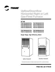
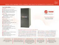
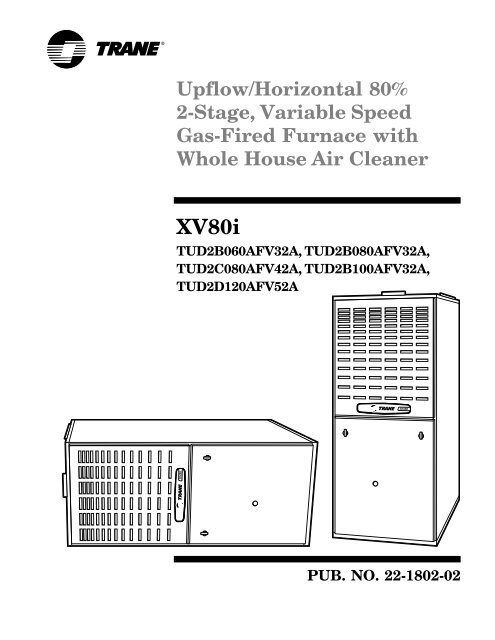
Upflow/Horizontal 80%2-Stage, Variable SpeedGas-Fired Furnace withWhole House Air CleanerXV80iTUD2B060AFV32A, TUD2B080AFV32A,TUD2C080AFV42A, TUD2B100AFV32A,TUD2D120AFV52APUB. NO. 22-1802-02
Features SummaryWHOLE HOUSE AIR CLEANERThe Whole House Air Cleaner usesadvanced technology to remove up to99.98% of allergens from the filteredair and removes particles down to .3microns in size. Cleaning intervals of1-3 months are typical, depending onthe home environment.NATURAL GAS MODELSCentral Heating furnace designs arecertified by the American GasAssociation for both natural and L.P.gas. Limit setting and rating datawere established and approved understandard rating conditions usingAmerican National StandardsInstitute standards.SAFE OPERATIONThe Integrated System Control hassolid state devices, which continuouslymonitor for presence of flame, whenthe system is in the heating mode ofoperation. Dual solenoid combinationgas valve and regulator provide extrasafety.QUICK HEATINGDurable, cycle tested, heavy gaugealuminized steel heat exchangerquickly transfers heat to provide warmconditioned air to the structure. Lowenergy power vent blower, to increaseefficiency and provide a positivedischarge of gas fumes to the outside.BURNERSMultiport In-shot burners will giveyears of quiet and efficient service. Allmodels can be converted to L.P. gas.INTEGRATED SYSTEM CONTROLExclusively designed operationalprogram provides total control offurnace limit sensors, blowers, gasvalve, flame control and includes selfdiagnostics for ease of service. Alsocontains connection points forhumidifier.AIR DELIVERYThe variable speed, direct driveblower motor, has sufficient airflowfor most heating and coolingrequirements, will switch fromheating to cooling speeds on demandfrom room thermostat. The blowerdoor safety switch will prevent orterminate furnace operation when theblower door is removed.STYLINGHeavy gauge steel and “wrap-around”cabinet construction is used in thecabinet with baked-on enamel finishfor strength and beauty. The heatexchanger section of the cabinet iscompletely lined with foil facedfiberglass insulation. This results inquiet and efficient operation due tothe excellent acoustical andinsulating qualities of fiberglass.Built-in bottom pan and bottomreturn air connection.FEATURES AND GENERALOPERATIONThe XV80i High Efficiency GasFurnaces employ a Hot SurfaceIgnition system, which eliminates thewaste of a constant burning pilot.The integrated system control lightsthe main burners upon a demand forheat from the room thermostat.Complete front service access.a. Low energy power venterb. Vent proving pressure switch.PUB. NO. 22-1802-022
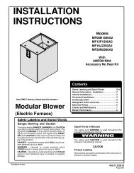
ContentsFeature SummaryFeatures and BenefitsStandard EquipmentOptional EquipmentGeneral DataTUD2B060AFV32ATUD2B080AFV32ATUD2C080AFV42ATUD2B100AFV42ATUD2D120AFV52APerformance DataElectric DataField Wiring DiagramsDimensions2468131520PUB. NO. 22-1802-023
Featuresand BenefitsXV80i STANDARD EQUIPMENT•Whole House Air Cleaner•Upflow/Horizontal•Power supply 115/1/60•2-stage gas valve•2-speed venter•Variable speed ECM blower motor•Silicon Nitride hot surface igniter withadaptive heat up•Integrated solid state control•Attractive color accents•Heavy gauge aluminized steel heatexchanger•Multi-port In-shot burners•Complete front service access•Alternate bottom/left/right return air•Slide out blower assembly•Hinged blower door•Perfect fit door catches•Insulated bower door•Gasketed blower door•Two tone color•Integrated solid state control withself-diagnostics•Common vent capability•Optional L.P. conversion kit•Left/right gas connection•Accessory hook-up capability•Selectable cooling fan off delay eliminatesneed for BAY24X045time delaykit•Enhanced cooling control•Non-prorated 20-year heat exchangerlimited warranty (Residentialuse)•5 Year limited parts warrantyPUB. NO. 22-1802-024
Featuresand BenefitsXV80i OPTIONAL EQUIPMENTThermostat, <strong>Mechanical</strong> 2-Stage Heating/ 1-Stage Cooling ............................................................................... TAYSTAT241 [ ]Thermostat, <strong>Mechanical</strong> Heating Only With Fan Switch .................................................................................. BAYSTAT303 [ ]Thermostat, <strong>Mechanical</strong> Heating Only ............................................................................................................... BAYSTAT388 [ ]Thermostat, Heating/Cooling Single Stage (Mounts Horizontally) ........................................................................ AY28X092 [ ]Thermostat, Electronic Non-programmable 1-Stage Heating/1-Stage Cooling .......................................... BAYSTAT370 [ ]Thermostat, Electronic Programmable (5-2) 1-Stage Heating/1-Stage Cooling ............................................... BAYSTAT340 [ ]Thermostat, Heating/Cooling Single Stage (Mounts Vertically) ........................................................................ BAYSTAT305 [ ]Thermostat, Electronic Programmable 2-Stage Heating/2-Stage Cooling ..................................................... TAYSTAT302C [ ]Thermostat, Electronic Programmable 1-Stage Heating/1-Stage Cooling ..................................................... TAYSTAT300C [ ]Propane Conversion Kit .................................................................................................................................... BAYLPKT210A [ ]Coil Enclosure (17-1/2” Wide Cabinets) ............................................................................................................. BAYCLE1700 [ ]Coil Enclosure (21” Wide Cabinets) ................................................................................................................... BAYCLE2100 [ ]Coil Enclosure (24-1/2” Wide Cabinets) ............................................................................................................. BAYCLE2400 [ ]High Altitude Switch ........................................................................................................................................... BAYHALT249 [ ]Masonry Chimney Vent Kit .............................................................................................................................. BAYVENT800B [ ]5PUB. NO. 22-1802-02
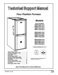
GeneralData<strong>Product</strong> Specifications 1MODELTYPERATINGS 21st Stage Input BTUH1st Stage Capacity BTUH (ICS) 32nd Stage Input BTUH2nd Stage Capacity BTUH (ICS) 3Temp. rise (Min.-Max.) °F.BLOWER DRIVEDiameter - Width (In.)No. UsedSpeeds (No.)CFM vs. in. w.g.Motor HPR.P.M.Volts / Ph / HzCOMBUSTION FAN — TypeDrive - No. SpeedsMotor HP - RPMVolts / Ph / HzFLAFILTER — Furnished?TypeMax. Indoor Relative Humidity 5VENT — Size (In.)HEAT EXCHANGERType -Fired-UnfiredGauge (Fired)ORIFICES — MainNat. Gas. Qty. — Drill SizeL.P. Gas Qty. — Drill SizeGAS VALVEPILOT SAFETY DEVICETypeBURNERS — TypeNumberPOWER CONN. — V / Ph / Hz 4Ampacity (In Amps)Max. Overcurrent Protection (Amps)PIPE CONN. SIZE (In.)DIMENSIONSCrated (In.)Uncrated (In.)WEIGHTShipping (Lbs.) / Net (Lbs.)*UD2B060AFV32AUpflow / Horizontal39,00031,20060,00048,00030 - 60Direct10 x 71VariableSee Airflow Table1/2Variable115/1/60CentrifugalDirect - 21/100 - 2543/1727115/1/600.70/0.40YesWhole House Air Cleaner65%4 RoundAlum. Steel - Type 1203 — 453 — 56Redundant - Two StageHot Surface IgnitionMulti-port In-shot3115/1/6010.5151/2H x W x D41-3/4 x 19-1/2 x 30-1/240 x 17-1/2 x 28-1/2136 / 126*UD2B080AFV32AUpflow / Horizontal52,00041,60080,00064,00030 - 60Direct10 x 71VariableSee Airflow Table1/2Variable115/1/60CentrifugalDirect - 21/100 - 2543/1727115/1/600.70/0.40YesWhole House Air Cleaner65%4 RoundAlum. Steel - Type 1204 — 454 — 56Redundant - Two StageHot Surface IgnitionMulti-port In-shot4115/1/6010.5151/2H x W x D41-3/4 x 19-1/2 x 30-1/240 x 17-1/2 x 28-1/2142 / 132*UD2C080AFV42AUpflow / Horizontal52,00041,60080,00064,00030 - 60Direct10 x 101VariableSee Airflow Table3/4Variable115/1/60CentrifugalDirect - 21/100 - 2543/1727115/1/600.70/0.40YesWhole House Air Cleaner65%4 RoundAlum. Steel - Type 1204 — 454 — 56Redundant - Two StageHot Surface IgnitionMulti-port In-shot4115/1/6012.9201/2H x W x D41-3/4 x 23 x 30-1/240 x 21 x 28-1/2166 / 1551 Central Furnace heating designs are certified by AGA and CSA.2 For U.S. applications, above input ratings (BTUH) are up to 2,000 feet, derate 4% per 1,000 feet for elevations above 2,000 feet above sea level. For Canadian applications, above inputratings (BTUH) are up to 4,500 feet, derate 4% per 1,000 feet for elevations above 4,500 feet above sea level.3 Based on U.S. government standard tests.4 The above wiring specifications are in accordance with National Electrical Code; however, installations must comply with local codes.5 The FIELD CHARGER may require more frequent cleaning in homes with high indoor relative humidity (greater than 65% RH). Consult your service professional about cleaningintervals.PUB. NO. 22-1802-026
GeneralDataMODELTYPERATINGS 21st Stage Input BTUH1st Stage Capacity BTUH (ICS) 32nd Stage Input BTUH2nd Stage Capacity BTUH (ICS) 3Temp. rise (Min.-Max.) °F.BLOWER DRIVEDiameter - Width (In.)No. UsedSpeeds (No.)CFM vs. in. w.g.Motor HPR.P.M.Volts / Ph / HzCOMBUSTION FAN — TypeDrive - No. SpeedsMotor HP - RPMVolts / Ph / HzFLAFILTER — Furnished?TypeMax. Indoor Relative Humidity 5VENT — Size (In.)HEAT EXCHANGERType -Fired-UnfiredGauge (Fired)ORIFICES — MainNat. Gas. Qty. — Drill SizeL.P. Gas Qty. — Drill SizeGAS VALVEPILOT SAFETY DEVICETypeBURNERS — TypeNumberPOWER CONN. — V / Ph / Hz 4Ampacity (In Amps)Max. Overcurrent Protection (Amps)PIPE CONN. SIZE (In.)DIMENSIONSCrated (In.)Uncrated (In.)WEIGHTShipping (Lbs.) / Net (Lbs.)<strong>Product</strong> Specifications 1*UD2B100AFV32AUpflow / Horizontal65,00052,000100,00080,00040 - 70Direct10 x 71VariableSee Airflow Table1/2Variable115/1/60CentrifugalDirect - 21/75 - 2708/1868115/1/600.87/0.49YesWhole House Air Cleaner65%4 RoundAlum. Steel - Type 1205 — 455 — 56Redundant - Two StageHot Surface IgnitionMulti-port In-shot5115/1/6010.8151/2H x W x D41-3/4 x 19-1/2 x 30-1/240 x 17-1/2 x 28-1/2142 / 132*UD2D120AFV52AUpflow / Horizontal78,00062,400120,00097,00035 - 65Direct10 x 101VariableSee Airflow Table1Variable115/1/60CentrifugalDirect - 21/60 - 3090/2225115/1/601.14/0.51YesWhole House Air Cleaner65%4 RoundAlum. Steel - Type 1206 — 456 — 56Redundant - Two StageHot Surface IgnitionMulti-port In-shot6115/1/6015.3201/2H x W x D41-3/4 x 26-1/2 x 30-1/240 x 24-1/2 x 28-1/2193 / 1811 Central Furnace heating designs are certified by AGA and CSA.2 For U.S. applications, above input ratings (BTUH) are up to 2,000 feet, derate 4% per 1,000 feet for elevations above 2,000 feet above sea level. For Canadian applications, above inputratings (BTUH) are up to 4,500 feet, derate 4% per 1,000 feet for elevations above 4,500 feet above sea level.3 Based on U.S. government standard tests.4 The above wiring specifications are in accordance with National Electrical Code; however, installations must comply with local codes.5 The FIELD CHARGER may require more frequent cleaning in homes with high indoor relative humidity (greater than 65% RH). Consult your service professional about cleaningintervals.PUB. NO. 22-1802-027
PerformanceDataHeating*UD2B060AFV32AAirflowSettingHeating1st StageHeating2ndStageLowMedium**HighLowMedium**HighFurnace Heating Airflow (CFM) and Power (watts) vs. External Static Pressure With FilterDip Switch SettingExternal Static PressureSW7 SW8 0.1 0.3 0.5 0.7 0.9CFM 583 590 625 622 620ON ON Temp. Rise 50 49 46 46 47Watts 60 87 126 157 192CFM 635 687 701 695 694ON OFF Temp. Rise 45 42 41 42 42Watts 69 110 148 183 221CFM 746 778 803 819 823OFF OFF Temp. Rise 39 37 36 35 35Watts 97 140 185 230 272CFM 779 816 848 866 874ON ON Temp. Rise 57 54 52 51 51Watts 104 152 201 255 302CFM 872 939 964 976 985ON OFF Temp. Rise 51 47 46 46 45Watts 136 203 264 312 365CFM 1069 1102 1102 1110 1078OFF OFF Temp. Rise 42 40 40 40 41Watts 227 293 345 403 429Cooling*UD2B060AFV32A Furnace Cooling Airflow (CFM) and Power (Watts) vs. External Static Pressure With FilterUnit AirflowDip Switch SettingExternal Static PressureOutdoor Setting SW1 SW2 SW3 SW4 0.1 0.3 0.5 0.7 0.9Low (350CFM 517 535 538 546 542ON ON OFF ONCFM/Ton)Watts 49 76 105 141 171Normal (400CFM 587 594 629 622 6181.5ON ON OFF OFFCFM/ton)Watts 61 89 129 159 196High (450CFM 642 677 705 701 696ON ON ON OFFCFM/ton)Watts 73 109 151 185 222Low (350CFM 676 705 729 736 738OFF ON OFF ONCFM/Ton)Watts 79 118 159 198 240Normal (400CFM 776 814 833 863 8672OFF ON OFF OFFCFM/ton)Watts 103 150 200 251 298High (450CFM 870 928 961 974 975OFF ON ON OFFCFM/ton)Watts 137 198 259 316 361Low (350CFM 831 883 915 935 941ON OFF OFF ONCFM/Ton)Watts 122 182 238 292 345Normal (400CFM 1023 1052 1055 1061 10482.5ON OFF OFF OFFCFM/ton)Watts 203 266 316 370 413High (450CFM 1156 1174 1188 1196 1085ON OFF ON OFFCFM/ton)Watts 280 351 415 482 442Low (350CFM 1063 1094 1090 1100 1070OFF OFF OFF ONCFM/Ton)Watts 226 290 344 397 430Normal**CFM 1214 1241 1263 1234 11233** OFF OFF OFF OFF(400Watts 320 395 476 514 469High (450CFM 1399 1409 1377 1278 1164OFF OFF ON OFFCFM/ton)Watts 486 575 604 559 507Notes:1. * First letter may be "A" or "T".2. ** Factory setting.3. Continuous Fan Setting: Heating or cooling airflow is approximately 50% of selected cooling value.4. For variable speed low speed airflows are approximately 30% of listed values.5. LOW 350 cfm/ton is recommended for variable speed application for COMFORT & HUMID CLIMATE setting; NORMAL is 400 cfm/ton;HIGH 450 cfm/ton is for DRY CLIMATE setting.PUB. NO. 22-1802-028
PerformanceDataHeating*UD2B080AFV32AAirflowSettingHeating1st StageHeating2ndStageLowMedium**HighLowMedium**HighFurnace Heating Airflow (CFM) and Power (watts) vs. External Static Pressure With FilterDip Switch SettingExternal Static PressureSW7 SW8 0.1 0.3 0.5 0.7 0.9CFM 846 852 836 811 810ON ON Temp. Rise 46 45 46 48 48Watts 127 167 200 229 270CFM 969 956 936 915 897ON OFF Temp. Rise 40 40 41 42 43Watts 182 218 251 283 317CFM 1126 1116 1108 1095 1074OFF OFF Temp. Rise 34 35 35 35 36Watts 270 316 361 404 441CFM 1216 1205 1189 1169 1111ON ON Temp. Rise 49 49 50 51 53Watts 333 383 429 468 473CFM 1362 1347 1324 1254 1145ON OFF Temp. Rise 44 44 45 47 52Watts 468 518 559 550 500CFM 1474 1419 1370 1258 1148OFF OFF Temp. Rise 40 42 43 47 52Watts 590 601 609 558 506Cooling*UD2B080AFV32A Furnace Cooling Airflow (CFM) and Power (Watts) vs. External Static Pressure With FilterUnit AirflowDip Switch SettingExternal Static PressureOutdoor Setting SW1 SW2 SW3 SW4 0.1 0.3 0.5 0.7 0.9Low (350CFM 934 926 913 889 863OFF ON OFF ONCFM/Ton)Watts 162 201 236 267 2962.5Normal (400CFM 1063 1051 1042 1029 1008OFF ON OFF OFFCFM/ton)Watts 228 272 315 356 394High (450CFM 1220 1212 1199 1179 1119OFF ON ON OFFCFM/ton)Watts 334 386 433 471 475Low (350CFM 1131 1122 1111 1101 1083ON OFF OFF ONCFM/Ton)Watts 269 317 361 405 4423Normal (400CFM 1310 1295 1273 1246 1136ON OFF OFF OFFCFM/ton)Watts 405 457 498 535 490High (450CFM 1458 1420 1369 1266 1154ON OFF ON OFFCFM/ton)Watts 569 599 606 561 506Low (350CFM 1329 1310 1287 1253 1142OFF OFF OFF ONCFM/Ton)Watts 424 472 516 542 4933.5**Normal (400CFM 1475 1422 1369 1272 1158OFF OFF OFF OFFCFM/ton)Watts 585 596 605 563 510High (450CFM 1473 1421 1367 1269 1152OFF OFF ON OFFCFM/ton)Watts 585 595 605 558 505Notes: rpm 1192 1239 1285 1303 13151. * First letter may be "A" or "T".2. ** Factory setting.3. Continuous Fan Setting: Heating or cooling airflow is approximately 50% of selected cooling value.4. For variable speed low speed airflows are approximately 30% of listed values.5. LOW 350 cfm/ton is recommended for variable speed application for COMFORT & HUMID CLIMATE setting; NORMAL is 400 cfm/ton;HIGH 450 cfm/ton is for DRY CLIMATE setting.9PUB. NO. 22-1802-02
PerformanceDataHeatingCooling*UD2C080AFV42A Furnace Heating Airflow (CFM) and Power (watts) vs. External Static Pressure With FilterAirflow Dip Switch SettingExternal Static PressureSetting SW7 SW8 0.1 0.3 0.5 0.7 0.9CFM 745 758 758 761 735Low ON ON Temp. Rise 52 51 51 51 52Watts 68 111 153 197 231CFM 839 864 851 851 822Medium** ON OFF Temp. Rise 46 45 45 45 47Watts 87 134 181 224 263CFM 934 961 943 941 933High OFF OFF Temp. Rise 41 40 41 41 41Watts 110 164 211 263 310CFM 1064 1077 1085 1086 1077Low ON ON Temp. Rise 56 55 55 55 55Watts 152 205 262 325 379CFM 1197 1226 1241 1230 1229Medium** ON OFF Temp. Rise 50 48 48 48 48Watts 201 271 338 395 462CFM 1345 1375 1376 1371 1320High OFF OFF Temp. Rise 44 43 43 43 45Watts 272 348 418 480 517Heating1st StageHeating2ndStage*UD2C080AFV42A Furnace Cooling Airflow (CFM) and Power (Watts) vs. External Static Pressure With FilterUnit AirflowDip Switch SettingExternal Static PressureOutdoor Setting SW1 SW2 SW3 SW4 0.1 0.3 0.5 0.7 0.9Low (350CFM 840 862 850 846 824ON ON OFF ONCFM/Ton)Watts 87 135 182 223 264Normal (400CFM 962 977 974 973 9652.5ON ON OFF OFFCFM/ton)Watts 118 167 221 276 320High (450CFM 1076 1095 1104 1102 1096ON ON ON OFFCFM/ton)Watts 153 212 271 331 390Low (350CFM 1004 1018 1016 1019 1007OFF ON OFF ONCFM/Ton)Watts 130 183 236 297 343Normal (400CFM 1143 1176 1187 1184 11803OFF ON OFF OFFCFM/ton)Watts 180 267 311 368 436High (450CFM 1303 1334 1337 1334 1296OFF ON ON OFFCFM/ton)Watts 252 326 394 456 502Low (350CFM 1167 1193 1208 1196 1193ON OFF OFF ONCFM/Ton)Watts 190 255 321 378 443Normal (400CFM 1356 1378 1383 1358 13213.5ON OFF OFF OFFCFM/ton)Watts 279 355 424 473 518High (450CFM 1521 1528 1537 1537 1344ON OFF ON OFFCFM/ton)Watts 379 545 534 606 556Low (350CFM 1351 1376 1377 1364 1312OFF OFF OFF ONCFM/Ton)Watts 275 357 422 467 515Normal**CFM 1537 1548 1561 1534 13474**OFF OFF OFF OFF(400Watts 392 468 552 606 538High (450CFM 1738 1755 1735 1568 1382OFF OFF ON OFFCFM/ton)Watts 543 652 708 635 563Notes:1. * First letter may be "A" or "T".2. ** Factory setting.3. Continuous Fan Setting: Heating or cooling airflow is approximately 50% of selected cooling value.4. For variable speed low speed airflows are approximately 30% of listed values.5. LOW 350 cfm/ton is recommended for variable speed application for COMFORT & HUMID CLIMATE setting; NORMAL is 400 cfm/ton;HIGH 450 cfm/ton is for DRY CLIMATE setting.PUB. NO. 22-1802-0210
PerformanceDataHeating*UD2B100AFV32AAirflowSettingHeating1st StageHeating2ndStageLowMedium**HighLowMedium**HighFurnace Heating Airflow (CFM) and Power (watts) vs. External Static Pressure With FilterDip Switch SettingExternal Static PressureSW7 SW8 0.1 0.3 0.5 0.7 0.9CFM 764 795 832 852 848ON ON Temp. Rise 63 61 58 56 57Watts 103 147 195 242 280CFM 875 938 963 974 959ON OFF Temp. Rise 55 60 58 57 58Watts 139 200 259 305 344CFM 984 1029 1040 1039 980OFF OFF Temp. Rise 49 47 46 46 49Watts 185 253 304 347 357CFM 1118 1138 1157 1125 1018ON ON Temp. Rise 66 65 64 66 73Watts 262 326 390 417 383CFM 1310 1335 1277 1192 1097ON OFF Temp. Rise 57 55 58 62 68Watts 411 498 498 472 441CFM 1413 1399 1322 1233 1148OFF OFF Temp. Rise 52 53 56 60 65Watts 512 566 541 514 484Cooling*UD2B100AFV32A Furnace Cooling Airflow (CFM) and Power (Watts) vs. External Static Pressure With FilterUnit AirflowDip Switch SettingExternal Static PressureOutdoor Setting SW1 SW2 SW3 SW4 0.1 0.3 0.5 0.7 0.9Low (350CFM 538 556 574 579 570ON ON OFF ONCFM/Ton)Watts 54 80 113 145 176Normal (400CFM 598 626 654 647 6471.5ON ON OFF OFFCFM/ton)Watts 64 94 131 162 200High (450CFM 657 706 713 724 730ON ON ON OFFCFM/ton)Watts 75 116 151 187 227Low (350CFM 688 729 745 753 763OFF ON OFF ONCFM/Ton)Watts 81 124 161 199 238Normal (400CFM 785 831 859 872 8812OFF ON OFF OFFCFM/ton)Watts 109 157 207 253 294High (450CFM 887 939 964 977 954OFF ON ON OFFCFM/ton)Watts 146 206 260 309 343Low (350CFM 848 907 934 946 946ON OFF OFF ONCFM/Ton)Watts 133 188 245 289 334Normal (400CFM 1018 1044 1055 1065 9832.5ON OFF OFF OFFCFM/ton)Watts 206 262 319 370 357High (450CFM 1139 1160 1184 1122 1020ON OFF ON OFFCFM/ton)Watts 274 344 411 417 386Low (350CFM 1071 1089 1105 1108 1003OFF OFF OFF ONCFM/Ton)Watts 231 290 346 399 368Normal (400CFM 1208 1246 1249 1153 10603.0**OFF OFF OFF OFFCFM/ton)Watts 323 411 469 441 410High (450CFM 1387 1383 1295 1221 1124OFF OFF ON OFFCFM/ton)Watts 482 546 517 499 467Notes:1. * First letter may be "A" or "T".2. ** Factory setting.3. Continuous Fan Setting: Heating or cooling airflow is approximately 50% of selected cooling value.4. For variable speed low speed airflows are approximately 30% of listed values.5. LOW 350 cfm/ton is recommended for variable speed application for COMFORT & HUMID CLIMATE setting; NORMAL is 400 cfm/ton;HIGH 450 cfm/ton is for DRY CLIMATE setting.11PUB. NO. 22-1802-02
PerformanceDataHeating*UD2D120AFV52A Furnace Heating Airflow (CFM) and Power (watts) vs. External Static Pressure With FilterAirflow Dip Switch SettingExternal Static PressureSetting SW7 SW8 0.1 0.3 0.5 0.7 0.9CFM 1003 1039 1062 1033 1034Low ON ON Temp. Rise 58 56 54 56 56Watts 125 182 246 309 356CFM 1137 1193 1185 1197 1185Medium** ON OFF Temp. Rise 51 48 49 48 49Watts 170 239 293 370 446CFM 1262 1290 1327 1344 1331High OFF OFF Temp. Rise 46 45 44 43 43Watts 218 286 366 440 534CFM 1415 1454 1476 1500 1421Low ON ON Temp. Rise 63 61 60 59 63Watts 297 378 453 534 561CFM 1645 1672 1701 1659 1456Medium** ON OFF Temp. Rise 54 53 52 54 61Watts 435 539 632 671 580CFM 1834 1857 1837 1686 1506High OFF OFF Temp. Rise 48 48 48 53 59Watts 608 705 778 699 630Heating1st StageHeating2ndStageCooling*UD2D120AFV52A Furnace Cooling Airflow (CFM) and Power (Watts) vs. External Static Pressure With FilterUnit AirflowDip Switch SettingExternal Static PressureOutdoor Setting SW1 SW2 SW3 SW4 0.1 0.3 0.5 0.7 0.9Low (350CFM 1141 1197 1205 1196 1188OFF ON OFF ONCFM/Ton)Watts 170 246 299 369 443Normal (400CFM 1325 1374 1403 1434 14123.5OFF ON OFF OFFCFM/ton)Watts 252 332 408 496 567High (450CFM 1536 1575 1615 1619 1474OFF ON ON OFFCFM/ton)Watts 370 464 563 640 605Low (350CFM 1334 1376 1424 1411 1417ON OFF OFF ONCFM/Ton)Watts 251 330 415 469 562Normal (400CFM 1582 1628 1659 1663 14654ON OFF OFF OFFCFM/ton)Watts 387 491 595 672 595High (450CFM 1813 1836 1838 1707 1504ON OFF ON OFFCFM/ton)Watts 577 684 771 710 620Low (350CFM 1704 1731 1733 1735 1552OFF OFF OFF ONCFM/Ton)Watts 489 589 666 750 663Normal (400CFM 1960 1971 1937 1799 16025** OFF OFF OFF OFFCFM/ton)Watts 739 841 891 813 700High (450CFM 2208 2107 1970 1849 1683OFF OFF ON OFFCFM/ton)Watts 1080 1025 942 863 776Notes:1. * First letter may be "A" or "T".2. ** Factory setting.3. Continuous Fan Setting: Heating or cooling airflow is approximately 50% of selected cooling value.4. For variable speed low speed airflows are approximately 30% of listed values.5. LOW 350 cfm/ton is recommended for variable speed application for COMFORT & HUMID CLIMATE setting; NORMAL is 400 cfm/ton;HIGH 450 cfm/ton is for DRY CLIMATE setting.PUB. NO. 22-1802-0212
ElectricalDataWIRING DIAGRAMS FOR GAS FURNACES13PUB. NO. 22-1802-02
ElectricalDataSCHEMATIC DIAGRAMS FOR GAS FURNACESPUB. NO. 22-1802-0214
FieldWiringSEENOTE 6FIELD WIRING DIAGRAM FOR VARIABLE SPEED 2 STAGE FURNACE1 STAGE HEATINGUSING A 1 STAGE HEATING THERMOSTATNO COOLINGY1/YloW14W14 JUMPERSEE NOTE 11SEENOTE 91. Be sure power agrees with equipment nameplates.2. Low voltage (24 volt wiring) to be No. 18 A.W.G. min.3. Grounding of equipment must comply with local codes.4. Set thermostat heat anticipator per unit wiring diagram.5. These leads provide 115V. power for connection of humidifierMAX. load 1.0 amp.6. When a single stage heating thermostat without fan switchis used, no wiring on "G" terminal is used.7. W1 and W2 must be jumpered together for proper operation.Second stage heat will begin 10 minutes after first stage.8. Set dip switches with power off per installation instructionsto set airflow and indoor fan off delays.9. Continuous fan airflow can be increased by adding this jumper.10. This wire is only for thermostats requiring connection totransformer common terminal.11. Optional humidistat is to be connected between R and BK. Factory installed jumper Rto BK on the circuit board must be cut if optional humidistat is used. The jumper mustalso be cut when applying an airflow command signal to the BK input such as with thevariable speed single-zone and multi-zone system controllers. On single speed coolingonly/non-heat pump systems, jumper Y to O for proper operation of the delay profilesand the humidistat. For two compressor or two speed systems, jumper YLo to O.FIELD ADDED JUMPERW1 TO W2.2ND STAGE WILL FIRE10 MINUTES AFTER 1ST.B/CSEENOTE 10B/CTO 115 V 1 PH.,60 HZ., POWERSUPPLY PERLOCAL CODESHUM SEENOTE 5From Dwg. B342027 Rev. 015PUB. NO. 22-1802-02
FieldWiringFIELD WIRING DIAGRAM FOR VARIABLE SPEED 2 STAGE FURNACE2 STAGE HEATINGUSING A 2 STAGE HEATING THERMOSTATNO COOLINGY1/YloW14W14 JUMPERSEE NOTE 9SEENOTE 71. Be sure power agrees with equipment nameplates.2. Low voltage (24 volt wiring) to be No. 18 A.W.G. min.3. Grounding of equipment must comply with local codes.4. Set thermostat heat anticipator per unit wiring diagram.5. These leads provide 115V. power for connection of humidifierMAX. load 1.0 amp.6. This wire is only for thermostats requiring connection totransformer common terminal.7. Continuous fan airflow can be increased by adding this jumper.8. Set dip switches with power off per installation instructionsto set airflow and indoor fan off delays.9. Optional humidistat is to be connected between R and BK. Factoryinstalled jumper R to BK on the circuit board must be cut if optionalhumidistat is used. The jumper must also be cut when applying an airflowcommand signal to the BK input such as with the variable speed single-zoneand multi-zone system controllers. On single speed cooling only/non-heat pumpsystems, jumper Y to O for proper operation of the delay profiles and the humidistat.For two compressor or two speed systems, jumper YLo to O.B/CSEENOTE 6B/CTO 115 V 1 PH.,60 HZ., POWERSUPPLY PERLOCAL CODESHUM SEENOTE 5From Dwg. B342025 Rev. 0PUB. NO. 22-1802-0216
FieldWiringFIELD WIRING DIAGRAM FOR VARIABLE SPEED 2 STAGE FURNACE1 STAGE HEATING, 1 STAGE COOLINGUSING A 1 STAGE HEATING, 1 STAGE COOLING THERMOSTAT(OUTDOOR SECTION WITHOUT TRANSFORMER)W14W14 JUMPERSEE NOTE 9OUTDOOR UNIT(NO TRANSFORMER)Y1/YloSEENOTE 7FIELD ADDED JUMPERW1 TO W2.2ND STAGE WILL FIRE10 MINUTES AFTER 1ST.B/CSEENOTE 6B/CTO 115 V 1 PH.,60 HZ., POWERSUPPLY PERLOCAL CODESHUM SEENOTE 5From drawing B342022 Rv 017PUB. NO. 22-1802-02
FieldWiringFIELD WIRING DIAGRAM FOR VARIABLE SPEED 2 STAGE FURNACE2 STAGE HEATING, 1 STAGE COOLINGUSING A 2 STAGE HEATING, 1 STAGE COOLING THERMOSTAT(OUTDOOR SECTION WITHOUT TRANSFORMER)W14SEENOTE 9W14 JUMPERSEE NOTE 9OUTDOOR UNIT(NO TRANSFORMER)Y1/YloSEENOTE 7B/CSEENOTE 6B/CTO 115 V 1 PH.,60 HZ., POWERSUPPLY PERLOCAL CODESHUM SEENOTE 5From Dwg. B342020 Rev. 0PUB. NO. 22-1802-0218
FieldWiringFIELD WIRING DIAGRAM FOR VARIABLE SPEED 2 STAGE FURNACE2 STAGE HEATING, 2 STAGE COOLING(OUTDOOR SECTION WITHOUT TRANSFORMER)W14OUTDOOR UNIT NO. 1(NO TRANSFORMER)SEE NOTE 3SEENOTE 7OUTDOOR UNIT NO. 2(NO TRANSFORMER)B/CSEENOTE 6B/CTO 115 V 1 PH.,60 HZ., POWERSUPPLY PERLOCAL CODESHUM SEENOTE 5From Dwg. B342018 Rev. 019PUB. NO. 22-1802-02
Dimensions*UD2 OUTLINE DRAWING(ALL DIMENSIONS ARE IN INCHES)MODEL DIM "A" DIM "B" DIM "C" DIM "D" DIM "E"*UD2B060AFV32A*UD2B080AFV32A*UD2B100AFV32A17-1/2" 9-5/8" 16-1/4" 16" 16"*UD2C080AFV42A 21" 13-1/16" 19-3/4" 19-1/2" 19-1/2"*UD2D120AFV52A 24-1/2" 15-5/16" 23-1/4" 23" 23"* PREFIX LETTER MAY BE "A" OR "T"Bottom Return ONLY
NOTES
TraneA business of American Standard companies6200 Troup HighwayTyler, TX 75707www.trane.comSince Trane has a policy of continuous product improvement, it reserves the right to change design andspecifications without notice.