TRC-SFD-1-07 - Tribology Group - Texas A&M University
TRC-SFD-1-07 - Tribology Group - Texas A&M University
TRC-SFD-1-07 - Tribology Group - Texas A&M University

Create successful ePaper yourself
Turn your PDF publications into a flip-book with our unique Google optimized e-Paper software.
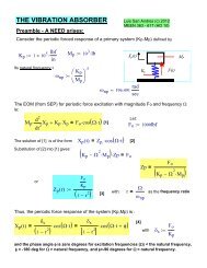
V Onset amplitude and frequency leading to air ingestion andlubricant cavitation in test <strong>SFD</strong>This section presents results from single frequency load excitation experimentsconducted on the <strong>SFD</strong> test rig with closed outlet ports (i.e. no thru-flow). The staticpressure at the inlet plenum and the discharge groove are 3 psia (31 kPa). Periodic loadsexcite the <strong>SFD</strong> inducing circular centered orbits with radii ranging from 31 μm to 74 μm(i.e. from 25% to 60% of radial clearance). The experiments serve to identify the limitorbital motion amplitudes for onset of air ingestion and lubricant cavitation. Table 3summarizes the test conditions.Table 3 Test conditions for dynamic load tests (CCO). Lubricated <strong>SFD</strong>. No thru-flow.Inlet pressure (P s ) *31 kPaDischarge groove pressure (P r )* 31 kPaFrequency range20-120 Hz (5 Hz step)Lubricant temperature (T) 25 0 C-26 0 C (76 0 F-79 0 F)Viscosity (η)3.1 cP- 2.8 cPClearance (c)125-127 μm (4.9-5 mils)Orbit amplitude (e)31-69 μm (1.2-2.7 mils)Flow restrictors (hole diameter) No thru-flow.*: Gauge pressure.V.1 Experimental procedureSingle frequency dynamic loads excite the test system with constant circular orbitamplitudes for the given range of frequencies (5, 10 Hz increments). The test maximumfrequency for each orbit amplitude is limited by the shaker maximum force. Specifically,the experiments are halted once the shakers output force reaches 80% (360 N) of theirmaximum capacity (445 N). For the smallest orbit amplitude tested (32 μm) the systemwas excited up to 110 Hz, and up to 50 Hz for the largest amplitude tested (74 μm).Figures 14 through 16 depict the excitation forces and corresponding damper orbitsfor 32 μm, 50 μm and 74 μm at the highest frequency tested for each amplitude level (i.e.110 Hz, 90 Hz and 50 Hz), respectively. Figures 13 and 15 show a fairly circular load andcircular bearing orbits. Figure 14 shows a more elliptical orbit for the excitation load andresponse orbit of 50 μm. The ellipticity may be attributed to the structural orthotropy of26