Temporary Revision 369/500/600 Series - MD Helicopters
Temporary Revision 369/500/600 Series - MD Helicopters
Temporary Revision 369/500/600 Series - MD Helicopters
- No tags were found...

Create successful ePaper yourself
Turn your PDF publications into a flip-book with our unique Google optimized e-Paper software.
<strong>369</strong>/<strong>500</strong>/<strong>600</strong> <strong>Series</strong><strong>Temporary</strong> <strong>Revision</strong>Manual: CSP-HMI-2, MAINTENANCE MANUALModels: <strong>369</strong>D/E/FF - <strong>500</strong>/<strong>600</strong>N <strong>Helicopters</strong>Issued: Issued: 31 October 1990<strong>Revision</strong> 44: 05 July 2011TR13−001: 20 March 2013FILING INSTRUCTIONS:1. Before you put this temporary revision in the manual, make sure the manual contains all therevisions from before. Look at the last revision List of Effective Pages.Do not put this temporary revision in the manual, if the manual does not containall the revisions from before.CAUTION2. To include this temporary revision in the manual, remove old pages and put in new pages asshown below.<strong>Temporary</strong> <strong>Revision</strong>Number/Date Section Page Page <strong>Revision</strong>TR13−001 / 20 March 2013 04−00−00 3 <strong>Revision</strong> 424 TR13−00111 TR13−00112 TR12−00328−00−00 iii TR13−001iv <strong>Revision</strong> 44405 <strong>Revision</strong> 44406 TR13−001603 TR13−001604 TR13−001605 TR13−001606 TR13−001607 TR13−001608 TR13−00163−25−10 201 TR13−001202 <strong>Revision</strong> 2091−00−00 15 TR12−00116 TR13−001
This Page Intentionally Left Blank
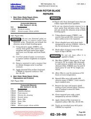
<strong>MD</strong> <strong>Helicopters</strong>, Inc.MAINTENANCE MANUALCSP-HMI-2REVISION: DATE FAA SIGNATURE AND DATE<strong>Revision</strong> 29: 11 May 2001<strong>Revision</strong> 30: 11 July 2001 Section 04−00−00 Not Affected This <strong>Revision</strong>TR 01−001: 10 August 2001<strong>Revision</strong> 31: 5 November 2001Section 04−00−00 Not Affected This <strong>Revision</strong>T/R 01−001 Previously SignedTR 02−002: 30 January 2002<strong>Revision</strong> 32: 18 March 2002<strong>Revision</strong> 33: 24 June 2002TR 03−001: 18 June 2003TR 03−002: 25 June 2003<strong>Revision</strong> 34: 21 August 2003Section 04−00−00 Not Affected This <strong>Revision</strong>T/R 03−001 and 03−002 Previously SignedTR 03−003: 30 September 2003TR 03−004: 17 December 2003<strong>Revision</strong> 35: 20 May 2004Section 04−00−00 Not Affected This <strong>Revision</strong>T/R 03−003 and 03−004 Previously SignedTR 04−001: 28 May 2004<strong>Revision</strong> 36: 11 November 2004<strong>Revision</strong> 37: 13 December 2005 Section 04−00−00 Not Affected This <strong>Revision</strong>TR 05−002: 16 December 2005<strong>Revision</strong> 38: 25 April 2006Section 04−00−00 Not Affected This <strong>Revision</strong>T/R 05−002 Previously SignedFAA APPROVED04-00-00Page 3<strong>Revision</strong> 42
CSP-HMI-2<strong>MD</strong> <strong>Helicopters</strong>, Inc.MAINTENANCE MANUALREVISION: DATE FAA SIGNATURE AND DATETR 06−001: 05 July 2006<strong>Revision</strong> 39: 10 April 2007 Section 04−00−00 Not Affected This <strong>Revision</strong>TR 07−001: 11 April 2007 Section 04−00−00 Not Affected This <strong>Revision</strong><strong>Revision</strong> 41: 03 March 2008TR 08−001 14 March 2008TR 08−002 07 November 2008<strong>Revision</strong> 42:Section 04−00−00 Not Affected This <strong>Revision</strong>T/R 08−001 and 08−002 Previously SignedTR 12−002 04 June 2012TR12−003 31 December 2012TR13−001 20 March 2013Page 4TR13-001 04-00-00 FAA APPROVED
<strong>MD</strong> <strong>Helicopters</strong>, Inc.MAINTENANCE MANUALCSP-HMI-2Component(1)Table 1. Airworthiness Limitations Schedule (Cont.)ModelPart Number(2)Tailboom assembly <strong>369</strong>D/E <strong>369</strong>D23<strong>500</strong> 10300<strong>369</strong>F/FF <strong>369</strong>D23<strong>500</strong>−507 10300Finite LifeHours(1)MandatoryInspectionHoursTailboom assembly <strong>500</strong>N <strong>500</strong>N3<strong>500</strong>−19 10204 100 (14)<strong>500</strong>N3<strong>500</strong>−29 10204<strong>500</strong>N3<strong>500</strong>−501 10204<strong>500</strong>N3<strong>600</strong>−501 10204 100 (14)<strong>600</strong>N <strong>600</strong>N3<strong>500</strong>−503 2<strong>500</strong> (25)<strong>600</strong>N3<strong>500</strong>−505 5900<strong>600</strong>N3<strong>500</strong>−507 1000<strong>600</strong>N3<strong>500</strong>−509 <strong>600</strong>0 (19)<strong>600</strong>N3<strong>500</strong>−511 <strong>600</strong>0 (19)<strong>600</strong>N3<strong>500</strong>−513 2<strong>500</strong> (25)<strong>600</strong>N3<strong>500</strong>−515 5900<strong>600</strong>N3<strong>500</strong>−517 1000Empennage fittings <strong>600</strong>N <strong>500</strong>N3530−7/8 On Cond. 100 (26)<strong>500</strong>N3530−9/10 On Cond. 100 (26)Vertical stabilizer assembly <strong>369</strong>D/E <strong>369</strong>D23<strong>600</strong> 12700<strong>369</strong>F/FF <strong>369</strong>D23<strong>600</strong>−505 3388Torque tube, horizontal stabilizer <strong>500</strong>N <strong>500</strong>N3950−5 <strong>500</strong>0<strong>600</strong>N <strong>500</strong>N3950−7 3000 (45)<strong>500</strong>N3950−9 3000 (45)<strong>600</strong>N3950−1 400<strong>600</strong>N3950−3 1000Horizontal stabilizer assembly <strong>369</strong>D (12) <strong>369</strong>D23601 7700<strong>369</strong>E (12) 421−087−505 7700421−087−905 (13) 7700<strong>369</strong>F/FF (12) 421−087−503 7700421−087−903 (13) 7700<strong>600</strong>N <strong>500</strong>N3910−25 10000 (19)<strong>500</strong>N3910−27 10000 (19)ControlsLongitudinal idler bellcrank assembly <strong>369</strong>D <strong>369</strong>A7301 6<strong>500</strong><strong>369</strong>A7301−501 6<strong>500</strong><strong>369</strong>E/F/FF <strong>369</strong>A7301−501 6<strong>500</strong><strong>500</strong>N <strong>369</strong>A7301−501 2870Idler assembly, longitudinal pitch mixer <strong>369</strong>D/E/F/FF <strong>369</strong>A7603 13<strong>600</strong><strong>500</strong>N <strong>369</strong>A7603 6050Longitudinal control rod <strong>500</strong>N <strong>369</strong>A7011−13 7740<strong>369</strong>A7011−15 7740Socket, cyclic stick <strong>600</strong>N <strong>369</strong>A7141 1000 8 (27)Cyclic tube assembly <strong>600</strong>N <strong>369</strong>D27132−503 1200 8 (27)FAA APPROVED04-00-00Page 11TR13-001
CSP-HMI-2<strong>MD</strong> <strong>Helicopters</strong>, Inc.MAINTENANCE MANUALComponent(1)Table 1. Airworthiness Limitations Schedule (Cont.)ModelPart Number(2)Housing, collective stick <strong>600</strong>N <strong>369</strong>A7347 450Tube, collective pitch control <strong>600</strong>N <strong>369</strong>A7348 400Tube assembly, collective pitch (pilot) <strong>600</strong>N <strong>369</strong>H7354−3 <strong>600</strong>Finite LifeHours(1)MandatoryInspectionHoursSocket, cyclic stick <strong>600</strong>N <strong>369</strong>A7802 1000 8 (27)Tube, collective pitch (co−pilot) <strong>600</strong>N <strong>369</strong>A7809 1800Housing, collective stick <strong>600</strong>N <strong>369</strong>A7820 450Housing, collective stick <strong>600</strong>N <strong>369</strong>H7837 450Tube assembly, collective pitch (co−pilot) <strong>600</strong>N <strong>369</strong>H7838−3 1000Fuselage Sta. 75 controls support bracket <strong>600</strong>N <strong>369</strong>N2608−11 <strong>600</strong>0 (41)<strong>600</strong>N2608−9 UnlimitedAirframeLanding gear brace <strong>600</strong>N <strong>600</strong>N6010−17/19 5900 (28)Landing gear strut <strong>600</strong>N <strong>600</strong>N6022−7 696 (29)<strong>600</strong>N6022−8 696 (29)<strong>600</strong>N6022−9 696 (29)<strong>600</strong>N6022−10 696 (29)<strong>600</strong>N6022−11 696 (29)<strong>600</strong>N6022−12 696 (29)<strong>600</strong>N6022−13 696 (29)<strong>600</strong>N6022−14 696 (29)Landing gear foot <strong>600</strong>N <strong>600</strong>N6043−3 3900 (30)Squib cartridge, used on Emergency floatkit <strong>369</strong>D292473−5, −6, −9, −10, −11, −12NOTE: Life is based from original date ofmanufacture.Floats<strong>369</strong>D/E/F/FF<strong>500</strong>N12552−1(Holex, Inc.)281993(Walter Kidde)12754−1(Holex, Inc.)<strong>500</strong>3527(Tavco)5 years5 years5 years5 yearsStabilizer support, utility float <strong>369</strong>D/E <strong>369</strong>D292036 3190<strong>369</strong>DSK66 3190NOTES:(1) Life−limited components interchanged between models or configurations must be restricted to the lowestservice life indicated for the models or configurations affected. Life−limited components removed atretirement are to be mutilated/destroyed or conspicuously marked to prevent inadvertent return to service.Parts are applicable only on models under which a service life is listed.Life−limited components cannot be altered or permanently marked in any manner without compromisingthe part integrity. Part tagging or other record keeping system is required.Related component records must be updated each time component is removed from service.(2) Service life shown for the basic (no dash number) part numbers apply to all dash numbered versionsunless otherwise indicated.Page 12TR12-003 04-00-00 FAA APPROVED
<strong>MD</strong> <strong>Helicopters</strong>, Inc.MAINTENANCE MANUALCSP−HMI−2TABLE OF CONTENTS (Cont.)Para/Figure/Table Title PageFigure 503. Fuel Filter Caution Light Pressure Switch (C30 Engine) ......... 509Figure 504. Fuel Filter Caution Light Pressure Switch (C20 Engines) ........ 509Figure 505. Fuel Filter Caution Light Pressure Switch (C20R/2 Engineswith CECO Pump) ........................................... 510Inspection/Check ............................................................. 6011. Fuel System General Inspection ............................................ 6012. Fuel Shutoff Valve Control Cable Swage Test (<strong>369</strong>D/E) ........................ 601Figure 601. Fuel Shut-Off Control Cable, PN <strong>369</strong>A8137-503 Pull Test ....... 6023. Fuel Shutoff Valve Inspection ............................................... 6034. Fuel Quantity Transmitter Inspection ....................................... 6035. Tank Vent System Inspection ............................................... 6046. Fuel System Vacuum Leak Inspection ....................................... 6047. Start Pump Operational Check (Model 250-C20 <strong>Series</strong> Enginesor 250-C30 Engine With Optional Maintenance Fuel Pump) .................. 6058. Drain Valve Inspection ..................................................... 6059. Fuel Cell Inspection ....................................................... 60610. Fuel Cell Leak Inspection .................................................. 606A. Soap Bubble Leak Test Procedures ........................................ 606B. Phenolphthalein Stain Inspection Procedures .............................. 607C. Liquid Stand Inspection .................................................. 60711. Fuel Tank Pressure Leak Test .............................................. 608Repairs ....................................................................... 8011. Fuel Shutoff Valve Control Cable Repair ..................................... 8012. Fuel Shutoff Valve Repair .................................................. 8013. Fuel Cell Repair ........................................................... 8014. Uniroyal Self-Sealing and Non-Self-Sealing Cell Repairs ..................... 801A. Scuff Mark Repair ....................................................... 802B. Reinforcements, Hangers and Splice Repairs ............................... 802C. Loose Patch Repair ...................................................... 802D. Patch Installation ....................................................... 802E. Loose Edge and Lap Seam Repairs ........................................ 804F. Blister Repair ........................................................... 8055. Fuel Quantity Transmitter Repair .......................................... 806A. Resistor installation, Transmitters PN <strong>369</strong>D296303, <strong>369</strong>D296303-701 and<strong>369</strong>A4245 .............................................................. 806B. MIL-S-8802 Application ................................................. 80728 ContentsPage iiiTR13−001
CSP−HMI−2<strong>MD</strong> <strong>Helicopters</strong>, Inc.MAINTENANCE MANUALTABLE OF CONTENTS (Cont.)Para/Figure/Table Title Page28-00-60 Fuel System (<strong>600</strong>N) ................................................... ADescription and Operation ................................................... 11. Engine Fuel System ....................................................... 12. Fuel Cells ................................................................. 13. Fuel Distribution .......................................................... 14. Fuel Vent System .......................................................... 15. Fuel Quantity System ..................................................... 26. Fuel Shutoff Valve Control ................................................. 27. Fuel Shutoff Valve ......................................................... 28. Fuel Filter Caution Light Pressure Switch ................................... 29. Drain System and Drain Valves ............................................. 210. Fuel Supply Lines ......................................................... 2Fault Isolation ............................................................... 1011. Fuel System Fault Isolation ................................................ 101Table 101. Fuel Supply System Fault Isolation ............................ 101Table 102. Fuel Quantity System Wire Data List ........................... 103Figure 101. Fuel Quantity System Wiring Diagram ........................ 103Maintenance Practices ....................................................... 2011. Fuel Cell Cleaning - General ............................................... 2012. Engineered Fabrics Corp. Fuel Cell Cleaning ................................. 2013. Fuel Cell Handling, Storage and Shipping ................................... 2014. Fuel Cell Preservation and Storage (Engineered Fabrics Corp. Cells) ........... 2015. Fuel System Air Bleed (Model 250-C47 Engine Installation) .................. 201Figure 201. Field Fabricated Fuel System Bleeding Tool .................... 202Removal/Installation ......................................................... 4011. Fuel Shutoff Valve Control Cable Replacement ............................... 401A. Fuel Shutoff Valve Control Cable Removal ................................. 401B. Fuel Shutoff Valve Control Cable Installation .............................. 401Figure 401. Fuel Shutoff Valve Cable Installation .......................... 4022. Fuel Shutoff Valve Replacement ............................................ 403A. Fuel Shutoff Valve Removal .............................................. 403B. Fuel Shutoff Valve Installation ........................................... 403Figure 402. Fuel Shutoff Valve and Fuel Cell Cover Installation ............. 404Page iv<strong>Revision</strong> 4428 Contents
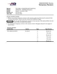
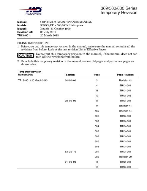
<strong>MD</strong> <strong>Helicopters</strong>, Inc.MAINTENANCE MANUALCSP-HMI-23. Fuel Tank Vent System ComponentReplacementAvoid fuel vapor ignitionWARNING and fire. Use only nonsparkingtools and explosion proof worklights. Attach helicopter to an approvedelectrical ground. Switch OFFall electrical power. Disconnect externalpower and battery before openingfuel system. Ensure work area is adequatelyventilated.Prevent fuel system contamination.Install caps on the ends ofCAUTIONhoses, tubes and fittings as parts are removed.Bag and identify small parts to preventloss or damage.(1). Defuel helicopter. Drain remaining fuelfrom tank sump drain valve into asuitable container.Prevent spontaneous combustionor explosion. NeverWARNINGuse oxygen to purge or ventilate fueltank or fuel system components. Fuel,either vapor or liquid, will violentlyreact with an oxygen rich atmosphere.(2). Ventilate fuel tank with an inert gas,such as nitrogen, or low pressurecompressed air applied through fillerneck.A. Vent Tube/Emergency Valve AssemblyRemoval(Ref. Figure 403)(1). Unbolt and remove right fuel cell accesscover.(2). Remove right foot support, controls,and fuel vent access panels.(3). Remove right seat from crew compartment.(4). Move collective pitch stick full down.(5). In passenger/cargo compartment;remove right and left fuel tank flooraccess panels.(6). Remove lockwire from vent connectorhoses and main rotor mast pan draintube.(7). Remove vent tube/emergency valveassembly attaching hardware. Removeflexible tubing from lower vent tube tee.(8). Rotate emergency shutoff valve inboardand slip assembly down over landinggear structure. Remove tube assemblythrough controls access panel opening.(9). Unclamp flexible tubing from side ventfairing. Remove tubing through controlsaccess opening.B. Forward Vent Crossover Fitting Removal(Ref. Figure 403)(1). Unbolt forward vent crossover fittingflanges.(2). Remove fitting, clamps, seals andwashers.(3). Cover cell vent fittings and aft vent linetube openings.C. Aft Vent Crossover Fitting Removal(Ref. Figure 403)NOTE: Left and right fuel cell access coversmust be removed to get at aft vent crossoverU-tube attaching hardware.(1). Remove left and right fuel cell flooraccess panels.(2). Unclamp fuel supply tube between fuelshutoff valve and Sta. 124.00 bulkheadelbow. Using backup wrench on bulkheadelbow so it will not rotate, disconnectand remove tube.(3). With 250-C20 <strong>Series</strong> Engines or250-C30 Engine With Optional MaintenanceFuel Pump: Unclamp start pumpwire harness and disconnect plug fromcell cover receptacle.(4). Unplug fuel quantity transmitterconnector from cell cover receptacle.(5). Unclamp and disconnect control cablefrom fuel shutoff valve.(6). Unfasten and remove Sta. 91.00 and102.00 left fuel cell cover supportbrackets.28-00-00Page 405<strong>Revision</strong> 44
CSP-HMI-2<strong>MD</strong> <strong>Helicopters</strong>, Inc.MAINTENANCE MANUALPANDRAIN TUBELOCKWIRECLIP(2 PLACES)WASHERLACING CORD(TYPICAL)WASHERBOLTBOLTWASHERCLAMPWASHERNUTFROM AFT VENTSIDE VENT FAIRINGVENT TUBELOCKWIRE(TYPICAL)CONNECTOR HOSE(NOTE 2)SUPPORT COILCLIPSCREWWASHERBOLT, TORQUE; 36-46 IN. LB(4.06-5.20 NM)WASHERCLAMPSSCREWWASHERFLEXIBLE TUBING(NOTE 1)ANTI-SIPHONHOLESSEAL WASHERSTAND-OFFWASHER (TYP)FUEL VENTCOVERINTERCONNECTFITTINGSEAL WASHERLOWER VENT FAIRINGFWD INTERCONNECT ANDEMERGENCY VALVE ASSYNOTES:1. ROUTED THRU LANDING GEAR BRACE.2. NOT TO BE PAINTED.G28-0003-1BFigure 403. Vent System (Sheet 1 of 2)Page 406TR13-001 28-00-00
<strong>MD</strong> <strong>Helicopters</strong>, Inc.MAINTENANCE MANUALCSP-HMI-2(e). Notch a 0.265 ID x 0.063 inch (6.73ID x 1.60 mm) thick washer andposition over cable between tape andback of instrument panel.Sudden cable separationWARNING may cause serious personalinjury. Be properly braced while pullingon the cable.(f). Apply a steady tension through thespring scale up to 50 pounds (222.4N). Relax the tension.(g). Inspect cable casing swage forseparation.(h). Replace separated/unserviceablecable assemblies.(i). If the swage held without apparentdamage, paint a green lacquer(CM309) stripe around the swage/casing joint.(3). Install and secure cable hardware.(4). Perform the following inspections andchecks on all model helicopters.(a). Remove left fuel cell floor accesspanel.(b). Inspect fuel shutoff cable, nylongrommets and attaching hardwarefor condition and security.(c). Operate cable and check for binding.Cable bend radius to be 3.5 inches,minimum.(d). Push knob in and check for 0.090 -0.150 inch (2.286 - 3.81 mm) gapbetween bottom of plunger and top ofplunger housing (Ref. Figure 401).3. Fuel Shutoff Valve Inspection(1). Shut down and disconnect all electricalpower.(2). In cargo/passenger compartment, openleft fuel cell access panel.(3). Disconnect fuel supply tube from fuelshutoff valve.(4). Use an inspection mirror and flashlightto check shutoff valve ball position.(5). Ensure shutoff valve control knob ispushed in. Valve ball must be wideopen.(6). Pull control knob out to stop. Valve ballshould be closed.(7). Valves that can not be fully closed oropened must be overhauled or replacedprior to further flight.(8). Disconnect control cable from valve.(9). Inspect shutoff valve lever and cableswivel hardware for corrosion and wear.Check lever for smooth movement fromclosed to open stops.(10). Use a spring scale to check tensionrequired to move valve lever from fullopen to closed. Design force requirementis 1.5 - 3.5 pounds (6.7 - 15.6 N)maximum.(11). Inspect valve for evidence of externalleakage. External leakage not allowed.(12). Check that lever detents at open andclosed positions. Repair or replace valveas required.(13). Connect and rig valve control cable.Install cotter pin on cable swivel.4. Fuel Quantity Transmitter Inspection(1). Remove left fuel cell floor access panel.(2). Check <strong>369</strong>D helicopters for pottingcompound on top of transmitter. Applymissing potting compound per repairinstructions. Check transmitterelectrical terminals and wire harnesswhere exposed for security and condition.(3). Where potting compound has beeninstalled, use a pointed probe andbright light to inspect interface betweenpotting compound and flange plate forvoids, debonding and separations.Inspect area around terminal fastenersfor voids. No separations or voids areallowed.(4). Remove and test unit as required.(5). Repair or replace potting compound.28-00-00Page 603TR13-001
CSP-HMI-2<strong>MD</strong> <strong>Helicopters</strong>, Inc.MAINTENANCE MANUAL5. Tank Vent System Inspection(1). Remove the controls access door,forward fuel vent crossover cover, righthand fuel compartment access door andthe compartment beneath the righthand flight crew member's structuralseat.(2). Inspect visible portions of the ventsystem hoses for deterioration and lookfor surface cracks. Replace hoses ifcracks are apparent.(3). Inspect visible portions of the venttubes and crossover fittings for dents,cracks, deformation or corrosion.Smooth nonrestrictive dents arepermissible.(4). Inspect visible portions of the emergencyshutoff valve for dents, cracks,deformation or corrosion. None allowed.(5). Disconnect hose P/N <strong>369</strong>D28107-1 fromthe forward crossover fitting and plugthe hose end.(6). Open the fuel filler port. Blow lowpressurecompressed air (less than 2.0psig) into the open end of the forwardvent crossover fitting and listen for airpassing through the tank vent to verifythe passage is clear and unobstructed.(7). Plug the side overboard vent fairingopenings and blow low pressurecompressed air (less than 2.0 psig) intothe lower overboard vent fairing. Listenfor air passage thru the fuel tank at thefiller port. This verifies the aft ventsystem and emergency shutoff valvewill pass air and system is clear andunobstructed. Unplug the side overboardvent fairing openings, plug thelower overboard vent fairing openingsand blow low pressure compressed airinto the side overboard vent fairing.Verify unobstructed airflow.(8). Unplug hose P/N <strong>369</strong>D281071 andblow low pressure air (less than 2.0psig) into the side overboard ventfairing. Feel for air coming out of theopen end of the hose, verifying unobstructedairflow. Unplug the loweroverboard vent fairing openings.Reconnect hose P/N <strong>369</strong>D281071 at theforward vent crossover fitting.(9). Check lower and side overboard ventfairing passages for obstructions andcondition. Repair or replace fairings asrequired (Ref. Sec. 53-20-00).(10). Emergency rollover valve part numbersOTHER than <strong>369</strong>H8108M,<strong>369</strong>H8108501M, <strong>369</strong>H8108503M<strong>369</strong>H8108505 and <strong>369</strong>D281081 aresubject to the functional check in step(a). below.(a). With vent tube removed, inspect venttube emergency shutoff valve forcondition. Valve should remain openwhen held vertical. Valve should beclosed when held in the 45° fromvertical position. While held in the45° position, blow in the valveassembly and check that valve isclosed (do not use compressed air).Valve shall open when returned tothe 25° position. If obstructed,replace valve.(11). Reinstall the controls access door, theforward fuel vent crossover cover, theright hand fuel compartment accessdoor and the compartment beneath theright hand flight crew member'sstructural seat.6. Fuel System Vacuum Leak InspectionFuel is drawn out of the tank by the enginedriven fuel pump when the START PUMP isswitched OFF on Model 250-C20 <strong>Series</strong>engine installations and at all times in Model250-C30 engine installations. Water, ice, dirt,fungus or a few pinhole leaks in the supplysystem between the fuel tank sump pickup andengine driven fuel pump may cause powersurges, deceleration and, or flameout. Avacuum leak inspection will determinewhether or not air is being drawn into theengine fuel supply system.ItemST801Special Tools(Ref. Section 91−00−00)NomenclatureHand operated vacuum pump kitPage 604TR13-001 28-00-00
<strong>MD</strong> <strong>Helicopters</strong>, Inc.MAINTENANCE MANUALCSP-HMI-2Air entering the airframeWARNING fuel supply lines may causea power reduction or flameout. Fuelsystem vacuum leak check and fuel airbleed procedures must be performedafter opening the fuel supply systemfor any reason, prior to releasing helicopterfor flight.(1). Remove left fuel cell floor access panel.(2). Pull FUEL shutoff valve knob out tostop. Verify that fuel shutoff valve leveris hard against its OFF stop.(3). In engine compartment; remove theupper drain plug from the fuel pumpfilter bowl.(4). On C30 and C20R installations, removeand plug the fuel vapor return line.(5). Assemble vacuum pump (ST801) hoses,filter port adapter, shutoff valve andvacuum gauge.(6). Install the vacuum gauge in the linebetween the filter port adapter andshutoff valve. Attach the vacuum pumpabove the shutoff valve.(7). Attach vacuum test vacuum pump toengine fuel filter upper drain port.Apply 8.0 Hg vacuum. Close vacuumline shutoff valve.(8). Fuel system shall hold vacuum between8.0 and 7.5 Hg for two minutes.NOTE: Vacuum loss exceeding 0.5 Hg in twominutes indicates a leak in the system between,and including, the fuel shutoff valveand engine.(9). If test is satisfactory, remove testvacuum. Inspect and replace filter plugO-ring as required. Install filter plug.(10). On C30 and C20R installations,reconnect and torque the fuel vaporreturn line.(11). Retorque fuel line connections (Ref.Table 401) and where installed, anti-ice(airframe) fuel filter fittings and linenuts (Ref. Sec. 28-25-00). Repeatvacuum test.(12). If system continues to leak, disconnectand install airtight caps on lines andfitting ports in a progressive sequencefrom fuel shutoff valve toward engine.The fuel shutoff and drain valveinstallations should be especiallysuspect. Apply vacuum at each stageuntil leak has been isolated. Replaceparts as required.NOTE: If the vacuum held at 7.5 Hg or better,airframe system seal is satisfactory andleak is due to an engine fuel system problem.Refer to the applicable Allison and Bendixmanuals for additional information.(13). Apply a torque stripe to all effected fuelline fittings and nuts.7. Start Pump Operational Check (Model250−C20 <strong>Series</strong> Engines or 250−C30 EngineWith Optional Maintenance Fuel Pump)(1). Remove fuel cell floor access panels.CAUTION(2). Refuel helicopter.Do not operate start pump in anempty fuel tank.(3). Connect battery and external power.(4). Set battery switch to EXT PWR.(5). Push FUEL shutoff valve knob in toopen shutoff valve.(6). Set START PUMP switch ON topressurize fuel system.(7). Inspect all line connections for leaks.(8). Shut down start pump.(a). Repair leaks as required.8. Drain Valve Inspection(1). Inspect tank sump drain valve forleakage and security. No leakageallowed.(2). Replace valve as required.28-00-00Page 605TR13-001
CSP-HMI-29. Fuel Cell Inspection<strong>MD</strong> <strong>Helicopters</strong>, Inc.MAINTENANCE MANUAL10. Fuel Cell Leak InspectionCAUTION Do not work on Uniroyal fuel cell in ambienttemperatures below 50°F (10°C). Do not work on Engineering Fabric Corp.fuel cell in ambient temperatures below70°F (21°C).ItemN/AN/AN/ACM218CM810CM820Consumable Materials(Ref. Section 91−00−00)NomenclatureAmmoniaCloth, cotton flannelPhenolphthalein, crystallineAlcohol, denaturedLeak detector, liquidCheesecloth Do not remove fuel cells unless absolutelyrequired. The barrier can be invisibly torn, puncturedor cracked by careless handling. Do not carry or move cell by its metal fittings. Never probe cell material with sharpedged or pointed tools.NOTE: Non-self-sealing and self-sealing cellsare primarily a 0.002 inch (0.051 mm)thick nylon barrier membrane sandwichedbetween lightweight constructionsof either rubberized (Uniroyal) orplasticized (Engineered Fabrics Corp.)nylon fabric that protects and strengthensthe barrier. Self-sealing cells may have one or morethin layers of natural rubber sandwichedbetween the barrier and fabric plies.(1). Apply protective tape to all machinedmetal fittings.(2). Perform cell inspection on a padded,clean, craft paper covered surface.(3). Inspect fuel cells per applicable manufacturersrequirements.Any one of three techniques can be used to findleaks in non-self-sealing and self-sealing fuelcells. The methods are listed in ascendingorder of effectiveness and complexity in termsof required equipment, materials, time, andeffort.Soap bubble leak inspection.Phenolphthalein stain inspection.Liquid stand inspection.NOTE: The soap bubble and phenolphthaleininspections require the cell to be inflatedwith air.(1). Manufacture or supply the followingequipment necessary to do soap bubbleor phenolphthalein inspections:(a). Rigid, airtight closures or plugs toseal all cell openings. Fit one coverplate with:(b). An air pressurization inlet fitting.(c). A manometer or an extremelyaccurate and sensitive low pressureair gauge.A. Soap Bubble Leak Test ProceduresNOTE: Soap bubble test reliability is good forbladder type non-self-sealing cells.(1). Remove cell from helicopter.(2). Lay cell out on a padded table. Installcell closures.(3). Inflate cell to 1/4 psi (1.7 kPa), maximum.Page 606TR13-001 28-00-00
<strong>MD</strong> <strong>Helicopters</strong>, Inc.MAINTENANCE MANUALCSP-HMI-2(4). Unless leak is immediately evident,maintain 1/4 psi (1.7 kPa) pressure fortwo hours to allow any air trapped incell exterior laps and seams to escape.(5). Run soap solution around all patches,lap joints, seams, fittings, creases,abrasions and any other suspiciousareas. Bubbles will appear over a leak.(6). Mark leak areas with a white or yellowcrayon.(7). Repair cell as required.B. Phenolphthalein Stain InspectionProcedures(1). Remove cell from helicopter.(2). Lay cell out on a padded table. Installall but one of the cell closures.(3). Make phenolphthalein solution asfollows:(a). Add 40 grams phenolphthaleincrystals to 1/2 gallon (1.9 L) ofdenatured alcohol (CM218) and stir.(b). Add 1/2 gallon (1.9 L) of water. Allowto stand 30 minutes. Stir beforeusing.(4). Pour commercial ammonia on anabsorbent cloth in a ratio of oneteaspoon (3 ml) per cubic foot of cellcapacity (minimum of 10 ml or 3.3teaspoons).(a). Place the ammonia saturated clothinside the cell and install the remainingcover.(b). Inflate cell with air to 1/4 psi (1.7kPa) maximum. Maintain 1/4 psi (1.7kPa) pressure for 15 minutes minimum,before proceeding.(c). Soak a large white cloth in thephenolphthalein solution. Thoroughlywring cloth out.(d). Spread and smooth cloth onto cell. Donot let cloth dry out.(e). A red spot will appear on the clothwhere there is a leak in the cell wall.Mark each leak.(f). Inspect the entire exterior surface ofthe cell.(5). Repair cell as required.C. Liquid Stand InspectionNOTE: Engineered Fabrics Corp. recommendsVITHANE\R cells be supported in a fixturefor the liquid stand inspection. Uniroyal rubberized fabric cells do not requiresupport for this test.(1). Remove cell from helicopter and placeon a clean, padded, kraft paper coveredtable.(2). Fabricate closure plates for each cellopening as follows:(a). The object is to completely fill the celland eliminate all air pockets.(b). Equip one of the plates with liquidfiller and vent stand pipes at least sixinches (15 cm) tall.(3). Fill the cell with Stoddard solvent,Stanisol or Varsoline.(4). Permit cell to stand undisturbed for 24hours.(5). Inspect paper to determine where cell isleaking.(6). Change paper as required. Drain, turnover, refill and let cell stand for another24 hours to ensure liquid has contactedall cell surfaces.(7). Repair cell as required.28-00-00Page 607TR13-001
CSP-HMI-2<strong>MD</strong> <strong>Helicopters</strong>, Inc.MAINTENANCE MANUAL11. Fuel Tank Pressure Leak TestCheck installed fuel tanks and plumbing forleaks as follows:ItemN/ASpecial Tools(Ref. Section 91−00−00)NomenclatureManometer(1). Plug vent system.(2). Remove left and right cell floor accesspanels.(3). Install manometer and air pressurizationequipment.(4). Apply 2 psi (14 kPa) air pressure for 10minutes to precondition cells. Thisforces trapped air from between fuelcells and helicopter structure. Ifnecessary, repeat until cells adjust tocontour of cell bay.(5). Apply 2 psi (14 kPa) air pressure for 15minutes with no visible, less than 1/4inch (6.35 mm) drop on manometer.NOTE: If pressure drop occurs, check all ventplugs, fittings and re-test cells.(6). Repair or replace parts as necessary toeliminate pressure drop.(7). Unplug vent system. Remove manometerand pressurization equipment.(8). Install left and right cell floor accesspanels.Page 608TR13-001 28-00-00
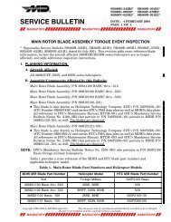
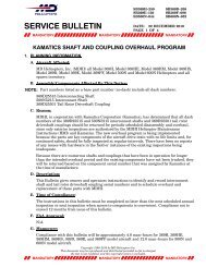
<strong>MD</strong> <strong>Helicopters</strong>, Inc.MAINTENANCE MANUALCSP-HMI-2TAIL ROTOR TRANSMISSION (TWO AND FOUR BLADE)MAINTENANCE PRACTICES1. Tail Rotor Transmission(Ref. Figure 201) The tail rotor transmission isa right-angle transmission with a magnesiumalloy housing. A magnetic chip detector islocated on the aft end of the transmission, abreather-filler is located on the top and a sightgage is mounted on the aft end (two-bladed) oron the right side (four-bladed) of the transmission.2. Tail Rotor Transmission ReplacementA. Tail Rotor Transmission Removal(1). Disconnect tail rotor driveshaft fromtransmission (Ref. Sec. 63-15-10).(2). Disconnect chip detector wire.(3). (<strong>369</strong>D/E) Remove four nuts andwashers from transmission mountstuds.(4). (<strong>369</strong>FF) Remove four bolts, eightwashers and four nuts between transmissionand tailboom extension.NOTE: Retain any shimming washers thatmay be between tail rotor transmission andtail boom for transmission installation.(5). With assistance, support transmissionand shaft in line for minimum deflectionof coupling and remove tail rotordrive shaft and transmission as a unit.(6). Remove tail rotor from tail rotortransmission (Ref. Sec. 64-20-00).(7). Remove tail rotor drive shaft from tailrotor transmission (Ref. Sec.63-15-10).B. Tail Rotor Transmission InstallationItemCM318Consumable Materials(Ref. Section 91−00−00)NomenclaturePrimerDo not carry or otherwise supporttransmission by coupling,CAUTIONas coupling diaphragm may be permanentlydistorted. During performance of all maintenanceon transmission, use extra care tokeep contaminants such as paint, dirt, etcfrom areas around input and output shaftseals.(1). Install tail rotor drive shaft on tail rotortransmission (Ref. Sec. 63-15-10).(Ref. Figure 203) Ensure securityof tail rotor transmissionCAUTIONmount studs. Maximum allowable side playat end of stud is 0.004 inch (0.102 mm),maximum allowable axial play is 0.005 inch(0.127 mm). For stud replacement, refer tothe Structural Repair Manual (SRM).NOTE: Ensure all paint and sealant is removedfrom mating surfaces. Remove excessivesealant, as required, from transmission togain clean mounting surfaces. Ensure thatno gap in sealant coverage exists around thetransmission bearing cover assembly.(2). Visually inspect mounting studs fordamage or deformation. Replacedamaged or deformed stud (Ref. SRM).(3). Apply primer (CM318) in holes and onthe grip area of the mounting studs.Install tail rotor transmission ortailboom extension while primer is stillwet.(4). With assistance, support transmissionand shaft in line for minimum deflectionof coupling and install tail rotordrive shaft and transmission as a unit(Ref. Sec. 63-15-10).NOTE: Note the drag torque for each nut andit's location on the transmission in the helicopterfor later use.(a). (<strong>369</strong>D/E) Secure tail rotor transmissionto four tailboom mounting studswith washers and nuts. Torque nutsto 75 - 95 inch-pounds (8.47 -10.73 Nm) plus drag torque.63-25-10Page 201TR13-001
CSP-HMI-2<strong>MD</strong> <strong>Helicopters</strong>, Inc.MAINTENANCE MANUALTRANSMISSIONCOUPLING (BENDIX)(CAUTION: DO NOT LIFTASSEMBLY FROM FLANGE)FAILSAFECOUPLING BOLTFAILSAFESOCKETCOUPLING BOLTOUTPUT SHAFTBREATHER FILLERCOUPLING(KAMATIC)INPUT SHAFTLIQUID LEVELPLUGCHIP DETECTOR2-BLADED TAIL ROTOR TRANSMISSIONCHIPDETECTORLIQUID LEVELPLUG4-BLADED TAIL ROTOR TRANSMISSIONG63-2014Figure 201. Tail Rotor Transmission − Stripping/BuildupPage 202<strong>Revision</strong> 20 63-25-10
<strong>MD</strong> <strong>Helicopters</strong>, Inc.MAINTENANCE MANUALCSP-HMI-2NumberNameNumberNameMS72Shell Chemical Co.910 Louisiana St.Houston, TX 77002713−241−6161MS83Varflex Corp.512 W. Court St.Rome, NY 13440(315) 336−4400MS73MS74MS75MS76MS77MS78MS79MS80MS81MS82Shell Oil Company50 W. 50th. St.New York, NY 10020Sherwin WilliamsStabond Corp.14010−T S. Western Ave.Gardena, CA 90249(310) 380−6168Technical Tape Co.363 Woodycrest Ave.Nashville, TN 37210(800) 714−8806ThiokolThomas and Betts Co.Elizabeth, NJTurco Products, IncDivision of Atochem North America2700 Temple Ave Suite BLong Beach, CA 90806(562) 981−8307Uniroyal Inc.Engineered Systems Dept.Mishawaka, IN 46544United−Erie Incorporated438 Huron St.Erie, PA 16502(800) 377−7561U.S. Rubber Co.Fuel Container Dept.Mishawaka, INMS84MS85MS86MS87MS88MS89MS90MS91Warren Wire Co.WitcoAllied−Kelite Division29111 Milford Rd.New Hudson, MI 48165(313) 437−81613M Co.Bldg. 223−N3M CenterSt. Paul, MN 55144−1000(612) 733−1110(800) 362−3550R.S, Hughes2107 E. MagnoliaPhoenix, AZ 85034(602) 275−5565(602) 275−5025Esgard Corrosion Coatings, PO Drawer2698, Lafayette, LA 70502(800) 888−2511Hernon Mfg., Inc.121−T Tech Dr.Sanford, FL 32771 USA(800) 527−0004(407) 322−4000Astronautics Corporation of America4115 N. Teutonia Ave.Milwaukee, WI, 53209www.astronautics.comTel: (414) 449−4000Fax: (414) 447−8231Chomerics, Inc.77 Dragon CourtWoburn, MA 01801(781) 935−485091-00-00Page 15TR12-001
CSP-HMI-2<strong>MD</strong> <strong>Helicopters</strong>, Inc.MAINTENANCE MANUALTable 3. Special ToolsItemNo. Part No. Nomenclature FunctionST101<strong>369</strong>A9905BDW-<strong>500</strong>MBDW-<strong>500</strong>HGround HandlingGround handling wheels(<strong>369</strong>D/E/FF can be used on<strong>500</strong>N)Mechanical Ground HandlingWheels (<strong>369</strong>D/E/FF - <strong>500</strong>N)Hydraulic Ground HandlingWheels (<strong>369</strong>D/E/FF - <strong>500</strong>N)BDW-<strong>600</strong>M Mechanical Ground HandlingWheels (<strong>600</strong>N)BDW-<strong>MD</strong>H Hydraulic Ground HandlingWheels (<strong>600</strong>N)ST102 <strong>369</strong>H9801 Handle-jack assembly,ground handling (straight)(<strong>369</strong>D/E/FF - <strong>500</strong>N)ST103 <strong>369</strong>A9906 Handle-jack assembly,ground handling (offset)(<strong>369</strong>D/E/FF - <strong>500</strong>N)ST104 <strong>369</strong>H90126 Ground handling wheels(one side)ST105 HT-<strong>500</strong> Tow bar (<strong>369</strong>D/E/FF, can beused on <strong>500</strong>N)ST201HT-<strong>500</strong>P<strong>369</strong>D29904<strong>600</strong>N9904Tow bar (<strong>500</strong>N/<strong>600</strong>N)Jacking and LevelingHoisting adapter (5-bladed)(6-bladed)Ground handling of helicopter.Raising or lowering helicopterwith ground handling wheels.Raising or lowering helicopterwith ground handling wheelswhen additional clearance is required.Ground handling of helicopterequipped with utility or emergencyfloats.Towing of helicopter.Hoisting entire helicopter or removingmain rotor.ST202 <strong>369</strong>A2010-5 Jack fittings Jacking, leveling or tiedown ofhelicopter.ST203 02-0520-0100 Hydraulic jack: 1-5 ton(900-4<strong>500</strong> kg)ST204 02-0234-0100 Hydraulic jack: 80-inch(203 cm) legST205KS 5490 oldKS 5549 newInclinometerJacking and leveling at Sta.90.61.Jacking and leveling at Sta.197.78.Angle of incidence tool, flightcontrol rigging.ST206 36-D-2844 Prop protractor Measure angle of incident.Main TransmissionST301 <strong>369</strong>H9807 Main transmission drainhoseDrain main transmission oil.Vendor(Table 4)TS21TS21TS15TS9Page 16TR13-001 91-00-00