MAIN ROTOR BLADE REPAIRS - MD Helicopters
MAIN ROTOR BLADE REPAIRS - MD Helicopters
MAIN ROTOR BLADE REPAIRS - MD Helicopters

Create successful ePaper yourself
Turn your PDF publications into a flip-book with our unique Google optimized e-Paper software.
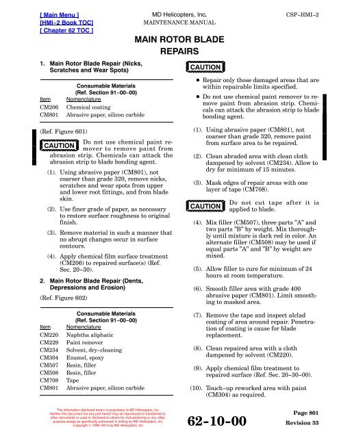
[ Main Menu ][HMI−2 Book TOC][ Chapter 62 TOC ]1. Main Rotor Blade Repair (Nicks,Scratches and Wear Spots)ItemCM206CM801Consumable Materials(Ref. Section 91−00−00)NomenclatureChemical coatingAbrasive paper, silicon carbide<strong>MD</strong> <strong>Helicopters</strong>, Inc.<strong>MAIN</strong>TENANCE MANUAL<strong>MAIN</strong> <strong>ROTOR</strong> <strong>BLADE</strong><strong>REPAIRS</strong>CAUTIONCSP-HMI-2 Repair only those damaged areas that arewithin repairable limits specified. Do not use chemical paint remover to removepaint from abrasion strip. Chemicalscan attack the abrasion strip to bladebonding agent.(Ref. Figure 601)Do not use chemical paint removerto remove paint fromCAUTIONabrasion strip. Chemicals can attack theabrasion strip to blade bonding agent.(1). Using abrasive paper (CM801), notcoarser than grade 320, remove nicks,scratches and wear spots from upperand lower root fittings, and from bladeskin.(2). Use finer grade of paper, as necessaryto restore surface roughness to originalfinish.(3). Remove material in such a manner thatno abrupt changes occur in surfacecontours.(4). Apply chemical film surface treatment(CM206) to repaired surface(s) (Ref.Sec. 20-30).2. Main Rotor Blade Repair (Dents,Depressions and Erosion)(Ref. Figure 602)(1). Using abrasive paper (CM801), notcoarser than grade 320, remove paintfrom surface area to be repaired.(2). Clean abraded area with clean clothdampened by solvent (CM234). Allow todry for minimum of 15 minutes.(3). Mask edges of repair areas with onelayer of tape (CM708).CAUTIONDo not cut tape after it isapplied to blade.(4). Mix filler (CM507), three parts ”A” andtwo parts ”B” by weight. Mix thoroughlyuntil mixture is dark red in color. Analternate filler (CM508) may be used ifequal parts ”A” and ”B” by weight aremixed.(5). Allow filler to cure for minimum of 24hours at room temperature.(6). Smooth filler area with grade 400abrasive paper (CM801). Limit smoothingto masked area.ItemCM220CM229CM234CM304CM507CM508CM708CM801Consumable Materials(Ref. Section 91−00−00)NomenclatureNaphtha aliphaticPaint removerSolvent, dry-cleaningEnamel, epoxyResin, fillerResin, fillerTapeAbrasive paper, silicon carbide(7). Remove the tape and inspect alcladcoating of area around repair. Penetrationof coating is cause for bladereplacement.(8). Clean repaired area with a clothdampened by solvent (CM220).(9). Apply chemical film treatment torepaired surface (Ref. Sec. 20-30-00).(10). Touch-up reworked area with paint(CM304) as required.The information disclosed herein is proprietary to <strong>MD</strong> <strong>Helicopters</strong>, Inc.Neither this document nor any part hereof may be reproduced or transferred toother documents or used or disclosed to others for manufacturing or any otherpurpose except as specifically authorized in writing by <strong>MD</strong> <strong>Helicopters</strong>, Inc.Copyright © 1999−2014 by <strong>MD</strong> <strong>Helicopters</strong>, Inc62-10-00Page 801Revision 33
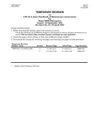
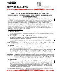
CSP-HMI-23. Trim Tab Damage Repair(Ref. Figure 802)<strong>MD</strong> <strong>Helicopters</strong>, Inc.<strong>MAIN</strong>TENANCE MANUAL[ Main Menu ][HMI−2 Book TOC][ Chapter 62 TOC ](6). If excessive damage requires full orpartial removal of trim tab from blade,perform the following (no minimumlength of trim tab is required):ItemCM206CM220CM234CM304CM318Consumable Materials(Ref. Section 91−00−00)NomenclatureChemical coatingNaphtha aliphaticSolvent, dry-cleaningEnamel, epoxyPrimer(a). Position blade on workbench so thata straight edge is provided for cuttingor filing off trim tab.Cutting, grinding or filing to removetrim tab, and deburring ofCAUTIONreworked blade trailing edge, are to be performedin a SPANWISE direction only. DoNOT use shears or clippers to remove trimtab.Provide protective surface and/CAUTIONor covering to prevent scratching,nicking or other damage to blade duringrework. Position blade on work bench orequivalent.NOTE: No minimum length of trim tab is required.In addition, the entire trim tab, orportion of the trim tab, may be removed ifrequired. Removal of entire trim tab eliminatesadjustment of blade tracking capabilityfor that blade. Main rotor blades with andwithout trim tabs are 100% interchangeable,individually and in ship sets.(1). Remove main rotor blade with damagedtrim tab.(2). Wipe away dirt on and around trim tabarea with clean cloth dampened withdry cleaning solvent (CM234).(3). Mask edges of blade area around trimtab area with tape; do NOT cut tapeafter it has been applied to blade.(4). Remove damaged area of trim tab bymaking V-type cut with 45° sidesjoined by a 0.25 inch (6.35 mm) radiusat the bottom of the V. Maximum V-cutdepth is 0.35 inch (8.89 mm); do not cutpast trim tab area into main portion ofblade.(5). If damage occurs within 1 inch (2.54cm) of either or both ends of trim tab,remove tab end(s) and restore contouras shown.(b). Use metal cutting saw or equivalentto remove the 0.38 inch (9.65 mm)wide trim tab per dimensions shownRef. Figure 802, View A-A). Deburredges in a SPANWISE direction only.(7). Peel and remove tape from blade andinspect area around repair; cleanrepaired area with cloth dampened innaptha (CM220).(8). Apply chemical film treatment (CM206)to reworked area of blade trailing edgeor trim tab; apply a thin film of primer(CM318) and paint (CM304) lightly.(9). Reinstall main rotor blade and performtrack and balance (Ref. Sec. 18-10).NOTE: Removal of entire trim tab eliminatesadjustment of blade tracking capability forthat blade.4. Forward Tip Cap Threaded Insert RepairItemCM318Consumable Materials(Ref. Section 91−00−00)NomenclaturePrimerReplace a loose or stripped insert. Useself-locking insert of correct size and installwith wet primer (CM318). Comply withreplacement requirements of applicable NASstandard.Page 802Revision 20 62-10-00The information disclosed herein is proprietary to <strong>MD</strong> <strong>Helicopters</strong>, Inc.Neither this document nor any part hereof may be reproduced or transferred toother documents or used or disclosed to others for manufacturing or any otherpurpose except as specifically authorized in writing by <strong>MD</strong> <strong>Helicopters</strong>, Inc.Copyright © 1999−2014 by <strong>MD</strong> <strong>Helicopters</strong>, Inc
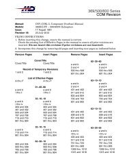
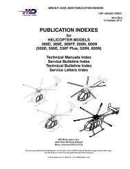
[ Main Menu ][HMI−2 Book TOC][ Chapter 62 TOC ]<strong>MD</strong> <strong>Helicopters</strong>, Inc.<strong>MAIN</strong>TENANCE MANUALCSP-HMI-2MS2070AD3RIVETS (2 PLS)6.312 INCH(16.033 CM)(REF)EXISTING<strong>BLADE</strong> RIVETEXISTING<strong>BLADE</strong> RIVETAEXISTING<strong>BLADE</strong> RIVET9.25 INCH(23.495 CM)A1.58 INCH(4.013 CM)(REF)0.75 INCH(19.05 MM)369D21106 UPPER EXTERNALTRAILING EDGE WEIGHT(369D21100 ONLY)369D21106 LOWER EXTERNALTRAILING EDGE WEIGHT(369D21100 ONLY)VIEW A-A(ROTATED 90°)NOTES:POSITION WEIGHT ONTO <strong>BLADE</strong> (ONEEACH ON UPPER AND LOWER SURFACES) BY ALIGNINGCENTERS OF HOLES IN WEIGHT TO EXISTING RIVETS ON <strong>BLADE</strong>.G62-1003AFigure 801. Main Rotor Blade Trailing Edge Weight Rework.The information disclosed herein is proprietary to <strong>MD</strong> <strong>Helicopters</strong>, Inc.Neither this document nor any part hereof may be reproduced or transferred toother documents or used or disclosed to others for manufacturing or any otherpurpose except as specifically authorized in writing by <strong>MD</strong> <strong>Helicopters</strong>, Inc.Copyright © 1999−2014 by <strong>MD</strong> <strong>Helicopters</strong>, Inc62-10-00Page 803Revision 20
CSP-HMI-25. Loose Balance Weight Repair(Ref. Figure 401) Reinstall loose forward and aftbalance weights as follows:ItemCM431Consumable Materials(Ref. Section 91−00−00)NomenclatureSealing, locking and retaining compound(1). Unscrew loose weight until it projectsapproximately one-half inch (12.7 mm)and remove old accumulation ofpowdered compound.(2). Apply grade A locking compound(CM431) and screw weight back intoblade until slotted end of weight isrecessed 0.050 inch (1.27 mm) below tipsurface. Wipe off excess compound.Allow to cure for a minimum ofCAUTION12 hours. If faster cure is desired,complete cure can be obtained by allowingpart to set for 30 minutes at roomtemperature and then heating for 30 minutesat approximately 212°F (101°C).(3). If locking compound is not available,screw weight into normal position andcenterpunch end of weight into matingthreads at three evenly spaced points toprevent rotation.6. Loose Trailing Edge Weight Repair(Ref. Figure 801)ItemCM220CM318CM409CM804Consumable Materials(Ref. Section 91−00−00)NomenclatureNaphtha aliphaticPrimerAdhesive, epoxyEmery cloth, fine(1). Carefully remove loose or partiallydebonded weights.(2). Abrade debonded surface using#200-300 grit emery cloth (CM804).(3). Clean bonding surfaces with napthaaliphatic (CM220).<strong>MD</strong> <strong>Helicopters</strong>, Inc.<strong>MAIN</strong>TENANCE MANUAL[ Main Menu ][HMI−2 Book TOC][ Chapter 62 TOC ](4). Mix epoxy adhesive (CM409) permanufacturer`s instructions and applyto bonding surfaces.(5). Position weights on blade by aligningholes in weights to existing rivet holeson blade and apply light pressure toweights until epoxy sets.(6). Install (3 ea.) rivets in existing holes.(7). If not already installed, install twomore rivets as follows.(a). Mark location of rivets to be installed.(b). Drill holes at marked locations.(c). Deburr and clean debris from holes.(d). Coat all exposed surfaces with primer(CM318).(e). Install rivets.(f). Allow epoxy adhesive to cure permanufacturer's instructions beforeflying aircraft.7. Loose or Missing Rivets or Aft Tip CapRepair(Ref. Figure 401) Replace all loose or missingrivets. Reinstall or replace loose or missing aft tipcap as follows:ItemCM234CM318CM411CM801Consumable Materials(Ref. Section 91−00−00)NomenclatureSolvent, dry-cleaningPrimerAdhesive, epoxyAbrasive paper, silicon carbideNOTE: Spare tip caps are supplied with bondingsurface coated with nylon primer to facilitateinstallation. Main rotor balance isnot affected by following repair.(1). Lightly abrade primed surfaces of tipcap with grade 180 abrasive paper(CM801). Wipe away residue with clothdampened in solvent (CM234) andallow tip cap to dry at room temperaturefor 30 minutes.(2). Mix two-part bonding adhesive(CM411) in equal proportions byweight.Page 804Revision 20 62-10-00The information disclosed herein is proprietary to <strong>MD</strong> <strong>Helicopters</strong>, Inc.Neither this document nor any part hereof may be reproduced or transferred toother documents or used or disclosed to others for manufacturing or any otherpurpose except as specifically authorized in writing by <strong>MD</strong> <strong>Helicopters</strong>, Inc.Copyright © 1999−2014 by <strong>MD</strong> <strong>Helicopters</strong>, Inc
[ Main Menu ][HMI−2 Book TOC][ Chapter 62 TOC ]<strong>MD</strong> <strong>Helicopters</strong>, Inc.<strong>MAIN</strong>TENANCE MANUALCSP-HMI-2NOTE 2NOTE 26.80 INCH (17.272 CM)TOPSURFACENOTES 2, 30.00 - 0.10 INCH(0.00 - 2.54 MM)0.38 INCH(9.652 MM)VIEW A-A0.38 INCH(9.652 MM)NOTE 11.00 INCH(2.54 CM)NOTE 3AANOTE 41.00 INCH(2.54 CM)NOTES:1. REMOVE DAMAGED END(S) IF THEY OCCUR WITHIN 1 INCH (2.54 CM) OF TAB ENDS.2. 0.25 INCH (6.35 MM) RADIUS CLEANUP. FINISH PER BASIC HMI.3. MAXIMUM DEPTH OF REPAIR 0.35 INCH (8.89 MM).4. NO MINIMUM LENGTH OF TAB REQUIRED. IF DAMAGE OCCURS AT BOTH ENDS, IT ISPERMISSIBLE TO REMOVE AT BOTH ENDS.5. ENTIRE TAB MAY BE REMOVED IF REQUIRED.G62-1004AFigure 802. Repair and Removal of Trim Tab, Main Rotor Blade0.002 INCH(0.0508 MM)MAXIMUMEDGE OFSTAKING TOOLARMFLUSH TO+0.010 INCH(+0.254 MM)BEARING WITH STAKINGGROOVE IN OUTER RACEPRESSINGBEARING IN ARMSTAKINGBEARING IN ARMG62-1005AFigure 803. Bearing Replacement − Main Rotor Blade Damper Attach FittingThe information disclosed herein is proprietary to <strong>MD</strong> <strong>Helicopters</strong>, Inc.Neither this document nor any part hereof may be reproduced or transferred toother documents or used or disclosed to others for manufacturing or any otherpurpose except as specifically authorized in writing by <strong>MD</strong> <strong>Helicopters</strong>, Inc.Copyright © 1999−2014 by <strong>MD</strong> <strong>Helicopters</strong>, Inc62-10-00Page 805Revision 20
CSP-HMI-2(3). Apply bonding adhesive to abraded tipcap and mating surfaces at rotor bladetip. To extent possible, be sure thatthere are no adhesive voids.(4). Install tip cap in blade tip, applyuniform clamping pressure to joint, andwipe away excessive adhesive. Allow tocure for eight hours at room temperatureor two hours at 150°F (66°C).(5). Install two MS20604AD3C2 blindrivets, one though each side of blade tipand tip cap.8. Damper Attach Blade Fitting BearingReplacement(Ref. Figure 803)ItemCM216CM219CM318ItemST709ST710Consumable Materials(Ref. Section 91−00−00)NomenclatureLoctite removerMethyl-ethyl-ketonePrimerSpecial Tools(Ref. Section 91−00−00)NomenclatureArbor press fixtureStaking tool(1). Use fly or circle cutter with 5/16 inch(7.9375 mm) pilot to remove staked lipfrom one side of bearing withoutremoving any material from fitting. Iffitting is damaged by cutter, blade mustbe replaced.(2). Use an arbor press to press bearingfrom fitting.(3). Clean primer residue from fitting borewith MEK (CM219). Remove lockingcompound residue, if any, with lockingcompound remover (CM216).(4). Using 10X magnifying glass, inspectfitting bore for cracks. No cracks arepermitted.<strong>MD</strong> <strong>Helicopters</strong>, Inc.<strong>MAIN</strong>TENANCE MANUAL[ Main Menu ][HMI−2 Book TOC][ Chapter 62 TOC ](5). Measure fitting bore diameter. Acceptablelimits are 0.7488-0.7493 inch(19.01952-19.03222 mm).(6). Apply thin coat of primer (CM318) tofitting bore.(7). Press bearing into fitting with arborpress and fixture (ST709). Wipe awayexcess primer.(8). Stake bearing at both sides of fittingwith staking tool (ST710) in hydraulicpress with 6000-8000 pounds(2722-3629 Kg) of force. When staked,outer race of bearing shall be flush tonot more than 0.010 inch (0.254 mm)above fitting surface (both sides). Gapbetween staked lip of bearing race andchamfered surface of fitting bore shallnot exceed 0.002 inch (0.0508 mm) aschecked with feeler gage. Stakingoperation shall produce no cracks infitting or bearing.(9). Fill staking gap, if any, with primer(CM318).9. Outboard Leading Edge Abrasion TapeReplacement(Ref. Figure 804 and Figure 805) Replaceabrasion tape when it is worn or eroded. Operationin rain or dust reduces tape life and more frequentreplacement is necessary.ItemCM220CM717CM801Consumable Materials(Ref. Section 91−00−00)NomenclatureNaphtha aliphaticTape, pressure sensitiveAbrasive paper, silicon carbideA. RemovalNOTE: A second abrasion tape may be appliedon top of the first tape to help replacementwhen top tape becomes eroded.(1). When only the top tape is replaced, peeloff top tape. Do not damage bottom tapebond to main rotor blade.(2). Wipe surface of bottom tape with aclean cloth dampened with napthaaliphatic (CM220) to remove anyadhesive.Page 806Revision 45 62-10-00The information disclosed herein is proprietary to <strong>MD</strong> <strong>Helicopters</strong>, Inc.Neither this document nor any part hereof may be reproduced or transferred toother documents or used or disclosed to others for manufacturing or any otherpurpose except as specifically authorized in writing by <strong>MD</strong> <strong>Helicopters</strong>, Inc.Copyright © 1999−2014 by <strong>MD</strong> <strong>Helicopters</strong>, Inc
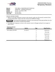
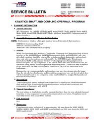
[ Main Menu ][HMI−2 Book TOC][ Chapter 62 TOC ](3). Do not allow naptha aliphatic (CM220)to touch the bond line between thebottom tape and the main rotor bladesurface.(4). If necessary, remove bottom tape frommain rotor blade.(5). Wipe main rotor blade surface with aclean cloth dampened with napthaaliphatic (CM220) to remove anyadhesive.<strong>MD</strong> <strong>Helicopters</strong>, Inc.<strong>MAIN</strong>TENANCE MANUALB. InstallationCSP-HMI-2(1). Lightly abrade faying surface of mainrotor blade with 400 grit abrasive paper(CM801).(2). Wipe faying surface of blade withnaptha aliphatic (CM220) to eliminategrease or dirt film.(3). Use heat gun or equivalent to warmblade faying surface. Temperature mustnot exceed 120°F (49°C).24.00 INCH(60.96 CM)A(NOTE 1)<strong>MAIN</strong> <strong>ROTOR</strong> <strong>BLADE</strong>AABRASION STRIP(369A1105)<strong>BLADE</strong> PROFILE (369D21105) (NOTE 2)ABRASION STRIP TIPEROSION 0.40 INCH(10.16 MM) MAXIMUMABRASION TAPE(369D21104 OR CM717)CHORDWISEBALL. WEIGHTVIEW A-A(NOTE 3)SKIN TIP EROSION0.30 INCH (7.62 MM)MAXIMUMNOTES:1. END OF TAPE TO BE FLUSH WITH OUTBOARD END OF <strong>BLADE</strong> SKIN. TAPETO BE SYMMETRICAL ABOUT LEADING EDGE.2. ABRASION TAPE MUST BE ALIGNED AT TOP PART OF <strong>BLADE</strong>.3. VIEW IS TYPICAL FOR 369D21100 <strong>BLADE</strong>S EXCEPT -505, -509, -511(SEE ALSO DN-39).G62-1006BFigure 804. Installation/Replacement of Abrasion Tape(Main Rotor Blade Leading Edge)The information disclosed herein is proprietary to <strong>MD</strong> <strong>Helicopters</strong>, Inc.Neither this document nor any part hereof may be reproduced or transferred toother documents or used or disclosed to others for manufacturing or any otherpurpose except as specifically authorized in writing by <strong>MD</strong> <strong>Helicopters</strong>, Inc.Copyright © 1999−2014 by <strong>MD</strong> <strong>Helicopters</strong>, Inc62-10-00Page 807Revision 45
CSP-HMI-2<strong>MD</strong> <strong>Helicopters</strong>, Inc.<strong>MAIN</strong>TENANCE MANUAL[ Main Menu ][HMI−2 Book TOC][ Chapter 62 TOC ]30.00 INCH(76.2 CM)(REF)M50459-1ABRASION TAPE(BOTTOM LAYER)A12.00 INCH(30.48 CM)0.50 INCH(12.7 MM)M50459-7ABRASION TAPE1.00 INCH(2.54 CM)A1.00 INCH(2.54 CM)369D21100-505 OR369D21100-509 <strong>MAIN</strong><strong>ROTOR</strong> <strong>BLADE</strong> ASSYM50459-1 ABRASIONTAPE (BOTTOM LAYER)369D21105OR369D21105-3ABRASION STRIP-7 ABRASION TAPE-1 ABRASION TAPENOTEVIEW A-ANOTE:ABRASION TAPE MUSTBE ALIGNED AT TOP SURFACE OF <strong>BLADE</strong>.G62-1007AFigure 805. Installation/Replacement of Double Layer Abrasion TapePage 808Revision 45 62-10-00The information disclosed herein is proprietary to <strong>MD</strong> <strong>Helicopters</strong>, Inc.Neither this document nor any part hereof may be reproduced or transferred toother documents or used or disclosed to others for manufacturing or any otherpurpose except as specifically authorized in writing by <strong>MD</strong> <strong>Helicopters</strong>, Inc.Copyright © 1999−2014 by <strong>MD</strong> <strong>Helicopters</strong>, Inc
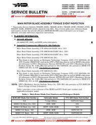
[ Main Menu ][HMI−2 Book TOC][ Chapter 62 TOC ](4). Remove backing and apply (CM717preferred over 369D21104) abrasiontape to outboard leading edge of mainrotor blade as follows:(a). Trim corners of abrasion tape to a0.25 inch (6.35 mm) radius to reducepeeling.<strong>MD</strong> <strong>Helicopters</strong>, Inc.<strong>MAIN</strong>TENANCE MANUAL(369D21100−505, −509 and −511 Rotor Blades)(b). Apply 6.50 inch (16.5 cm) wide and24 inch (61 cm) long abrasion tapealong blade leading edge (Ref.Figure 804) so tape overlaps bottomand top of blade edge equally or (Ref.Figure 805) for 369D21100-505, -509and -511 blades.(c). Smooth and press abrasion tape intoplace by hand. Use heat gun orequivalent to maintain temperature.(d). Re-apply pressure by hand followinginitial installation to make sure ofproper bonding. Abrasion tape mustbe free of surface wrinkles or airbubbles.NOTE: A second abrasion tape may be appliedon top of the first tape to facilitate replacementwhen top tape becomes eroded. To applysecond tape, wipe surface of installedstrip clean with naptha aliphatic (CM220)and repeat steps (3). and (4). above. Secondabrasion tape must be evenly aligned withfirst at top surface of blade (Ref. Figure 804or Figure 805).10. Leading Edge Abrasion Strip Sealing(Ref. Figure 805)ItemCM219CM228CM404Consumable Materials(Ref. Section 91−00−00)NomenclatureMethyl-ethyl-ketoneSurface cleanerAdhesive, epoxy(1). Remove screw and tip cap from mainrotor blade.(2). Remove any loose or cracked sealant oradhesive from areas of main rotorblade.CSP-HMI-2MEK is flammable. Use inWARNING well ventilated area andaway from open flame.(3). Clean areas to be sealed with cleancloth moistened with solvent (CM228).For hard to clean problem areas, MEK(CM219) may be used.(4). Prepare adhesive (CM404) permanufacturer's instructions.(5). Apply bead of adhesive to interface ofabrasion strip and blade skin. Ensurethere are no gaps or bridges in bead.(6). Cure adhesive per manufacturer'sinstructions.11. Tip Cap Sealing(Ref. Figure 805)ItemCM212CM213CM318CM420CM427CM428Consumable Materials(Ref. Section 91−00−00)NomenclatureReleasing agentReleasing agentPrimerSealantSealing compoundSealing compound(1). Apply release agent (CM212 or CM213)to inside of tip cap per manufacturer'sinstructions.(2). Prepare and apply a 0.010-0.020 inch(0.254-0.508 mm) coating of sealant(CM420, CM427 or CM428) to fayingsurfaces per manufacturer's instructions.(3). Attach tip cap to blade and installscrew with primer (CM318).(4). Wipe off squeezed out sealant flushwith surface.NOTE: To inhibit moisture entering bond jointof abrasion strip after initial application,reapply sealant, when sealant is worn awayor becomes cracked.The information disclosed herein is proprietary to <strong>MD</strong> <strong>Helicopters</strong>, Inc.Neither this document nor any part hereof may be reproduced or transferred toother documents or used or disclosed to others for manufacturing or any otherpurpose except as specifically authorized in writing by <strong>MD</strong> <strong>Helicopters</strong>, Inc.Copyright © 1999−2014 by <strong>MD</strong> <strong>Helicopters</strong>, Inc62-10-00Page 809Revision 45
CSP-HMI-2<strong>MD</strong> <strong>Helicopters</strong>, Inc.<strong>MAIN</strong>TENANCE MANUAL[ Main Menu ][HMI−2 Book TOC][ Chapter 62 TOC ]CCAA0.75 INCH(19.05 MM)SEAL WITH EC2216 B/A FROM L.E. TO0.75 INCH (19.05 MM) DIM. ON T.E.RADIUS (UPPER AND LOWER SURFACE)0.75 INCH(19.05 MM)C369A1116 TIP CAPSEAL WITHPR1436G, CLASS B-2ORPR1422G, CLASS BC369D21100 <strong>MAIN</strong> <strong>ROTOR</strong> <strong>BLADE</strong> ASSEMBLY369D21105 ABRASION STRIP REF.369A1103 SKIN REF.0.003-0.005 INCH(0.0762-0.127 MM) TYP.SEAL WITHEC2216 B/ASEAL WITHEC2216 B/A369A1109-501, 269A1186BAL. WT. REF.0.010 INCH(0.254 MM)TYPSEAL SKIN / BAL. WT.ASSY INTERFACEWITH EC2216 B/A0.12 INCH(3.048 MM)TYPA-ATIP CAP OMITTED FOR CLARITYC-CTYP 2 PLCS369A1103 SKIN369D21105 ABRASION STRIPSEAL SCREW BY INSTALLINGWITH WET PRIMERNAS517-3-0G62-1013AFigure 806. Main Rotor Blade Abrasion Strip and Tip Cap SealingPage 810Revision 20 62-10-00The information disclosed herein is proprietary to <strong>MD</strong> <strong>Helicopters</strong>, Inc.Neither this document nor any part hereof may be reproduced or transferred toother documents or used or disclosed to others for manufacturing or any otherpurpose except as specifically authorized in writing by <strong>MD</strong> <strong>Helicopters</strong>, Inc.Copyright © 1999−2014 by <strong>MD</strong> <strong>Helicopters</strong>, Inc
[ Main Menu ][HMI−2 Book TOC][ Chapter 62 TOC ]12. Main Rotor Blade Protective TapeInstallationIn an effort to reduce the amount of erosion inthe area inboard of the abrasion strip, <strong>MD</strong>HIhas approved the installation of stainless steelor Mylar tape to the blade leading edge.Installation of the tape is optional.The approved 3M Mylar tape, P/N 8671-1, isone inch (2.54 cm) wide and the 304 stainlesssteel tape, P/N 87-369D21104, is 0.027 inch(0.6858 mm) thick and two inch (5.08 cm)wide.The length of the tape can vary, up to 8.0inches (20.32 cm) in length, but must be equalon all blades.It is recommended to start with 2.5 inch (6.35cm) length and increase the length as erosionoccurs by replacing the tape.NOTE: This installation is only approved onmain rotor blades equipped with the 36inch (91.44 cm) abrasion strips. For installation of the Mylar tape, refer tomanufacturer's instructions. Use of aerosolprimer Promoter 86 may be used tospeed cure time of the tapes adhesive.Mylar tape comes in rolls one inch (2.54cm) wide by 36 yards (329184 m) in lengthand the promoter comes in 36 ounce(1.065 L) cans. Mylar tape can be purchasedfrom RS Hughes Company(1-800-453-8116).A. Stainless Steel Tape InstallationItemCM220CM801Consumable Materials(Ref. Section 91−00−00)NomenclatureNaphtha aliphaticAbrasive paper, silicon carbideDo not cut or trim tape afterCAUTIONinstallation on blade, damage toblade will occur.(1). Measure length of eroded area on bladewith the most erosion.<strong>MD</strong> <strong>Helicopters</strong>, Inc.<strong>MAIN</strong>TENANCE MANUALCSP-HMI-2NOTE: Tape must be of equal length on allblades to ensure proper balance.(2). Cut tape long enough to cover erosionplus approximately one-half inch (12.7mm) overlap on leading edge abrasionstrip.(3). Round off square corners of tape toreduce peeling.(4). Lightly abrade faying surface of mainrotor blade in area where tape is to beinstalled with 400-grit abrasive paper(CM801).(5). Wipe abraded area with naphthaaliphatic (CM220) to eliminate greaseand dirt film.(6). Treat any bare metal with epoxy-typepaint.NOTE: Do not allow temperature to exceed120°F (49°C).(7). Using a heat gun, or equivalent, heatabraded area.(8). Apply aerosol primer to bonding areaand allow to dry.(9). Remove backing and apply tape toleading edge of blade.(a). Apply tape so it overlaps each side ofblade equally.(b). Tape should overlap the inboard endof abrasion strip 0.5 ±0.03 inch (12.7±0.762 mm) at the leading edge ofblade.NOTE: Tape must be free of surface wrinkles orair bubbles.(10). Smooth and press tape into place byhand.(11). Re-apply pressure by hand followinginitial installation to ensure properbonding.(12). Perform main rotor balance (Ref. Sec.18-10-00 or 18-10-60).The information disclosed herein is proprietary to <strong>MD</strong> <strong>Helicopters</strong>, Inc.Neither this document nor any part hereof may be reproduced or transferred toother documents or used or disclosed to others for manufacturing or any otherpurpose except as specifically authorized in writing by <strong>MD</strong> <strong>Helicopters</strong>, Inc.Copyright © 1999−2014 by <strong>MD</strong> <strong>Helicopters</strong>, Inc62-10-00Page 811Revision 46
CSP-HMI-2<strong>MD</strong> <strong>Helicopters</strong>, Inc.<strong>MAIN</strong>TENANCE MANUAL[ Main Menu ][HMI−2 Book TOC][ Chapter 62 TOC ]This Page Intentionally Left BlankPage 812Revision 44 62-10-00The information disclosed herein is proprietary to <strong>MD</strong> <strong>Helicopters</strong>, Inc.Neither this document nor any part hereof may be reproduced or transferred toother documents or used or disclosed to others for manufacturing or any otherpurpose except as specifically authorized in writing by <strong>MD</strong> <strong>Helicopters</strong>, Inc.Copyright © 1999−2014 by <strong>MD</strong> <strong>Helicopters</strong>, Inc