TEMPORARY REVISION - MD Helicopters
TEMPORARY REVISION - MD Helicopters
TEMPORARY REVISION - MD Helicopters

You also want an ePaper? Increase the reach of your titles
YUMPU automatically turns print PDFs into web optimized ePapers that Google loves.
CSP−H−2<strong>MD</strong> <strong>Helicopters</strong>, Inc.500 Series − Basic HMITABLE OF CONTENTS (Cont.)Para/Figure/Table Title PageB. Storage up to 45 Days . . . . . . . . . . . . . . . . . . . . . . . . . . . . . . . . . . . . . . . . . . . . . . . . . . . . . . 2−60C. Storage up to 6 Months . . . . . . . . . . . . . . . . . . . . . . . . . . . . . . . . . . . . . . . . . . . . . . . . . . . . . 2−6116. Torque Data . . . . . . . . . . . . . . . . . . . . . . . . . . . . . . . . . . . . . . . . . . . . . . . . . . . . . . . . . . . . . . . . . 2−62A. Torque Wrenches . . . . . . . . . . . . . . . . . . . . . . . . . . . . . . . . . . . . . . . . . . . . . . . . . . . . . . . . . . . 2−6217. Torque Wrench Load Application . . . . . . . . . . . . . . . . . . . . . . . . . . . . . . . . . . . . . . . . . . . . . . 2−6218. Installation, Staking or Swaging Force Needed for Bearings . . . . . . . . . . . . . . . . . . . . . 2−6419. Useful Conversion Data . . . . . . . . . . . . . . . . . . . . . . . . . . . . . . . . . . . . . . . . . . . . . . . . . . . . . . 2−6420. Related Publications . . . . . . . . . . . . . . . . . . . . . . . . . . . . . . . . . . . . . . . . . . . . . . . . . . . . . . . . . 2−6421. Maintenance Information Requests . . . . . . . . . . . . . . . . . . . . . . . . . . . . . . . . . . . . . . . . . . . . 2−6422. Inspection Practices and Technical Definitions . . . . . . . . . . . . . . . . . . . . . . . . . . . . . . . . . . 2−6423. Service and Operations Report Form 853 . . . . . . . . . . . . . . . . . . . . . . . . . . . . . . . . . . . . . . . 2−64Table 2−5. Recommended Standard Torques for Tension−Type Nut:Min. and Max. Torque Values; AN310, AN365, MS20365, MS21042,NAS1021, NAS1291, NAS679 . . . . . . . . . . . . . . . . . . . . . . . . . . . . . . . . . . . . . . . . . . . . . . 2−65Table 2−6. Recommended Standard Torques for Shear−Type Nut:Min. and Max. Torque Values; AN320, AN364, MS20364, NAS1022,MS21083 . . . . . . . . . . . . . . . . . . . . . . . . . . . . . . . . . . . . . . . . . . . . . . . . . . . . . . . . . . . . . . . . 2−66Table 2−7. Self−Locking Nut Minimum Run−On Torque Values . . . . . . . . . . . . . . . . . . . 2−67Table 2−8. Minimum Breakaway Torque For Used Self−locking Bolts or Screws . . . . 2−67Table 2−9. Special Torques . . . . . . . . . . . . . . . . . . . . . . . . . . . . . . . . . . . . . . . . . . . . . . . . . . . 2−68Table 2−10. Temperature Convervision . . . . . . . . . . . . . . . . . . . . . . . . . . . . . . . . . . . . . . . . . 2−71Table 2−11. Conversion of Inches to Millimeter . . . . . . . . . . . . . . . . . . . . . . . . . . . . . . . . . . 2−72Table 2−12. Conversion of Millimeter to Inches . . . . . . . . . . . . . . . . . . . . . . . . . . . . . . . . . 2−72Table 2−13. Conversion of Fractional Inches to Decimals and Millimeter . . . . . . . . . . 2−73Table 2−14. Conversion of U.S. Measure used in Servicing and Maintenance . . . . . . 2−73Table 2−15. Related Publications and Directives . . . . . . . . . . . . . . . . . . . . . . . . . . . . . . . . 2−74Figure 2−10. Technical Definitions . . . . . . . . . . . . . . . . . . . . . . . . . . . . . . . . . . . . . . . . . . . . . 2−78Table 2−16. Technical Definitions . . . . . . . . . . . . . . . . . . . . . . . . . . . . . . . . . . . . . . . . . . . . . 2−79Page 2−ivTR09−001
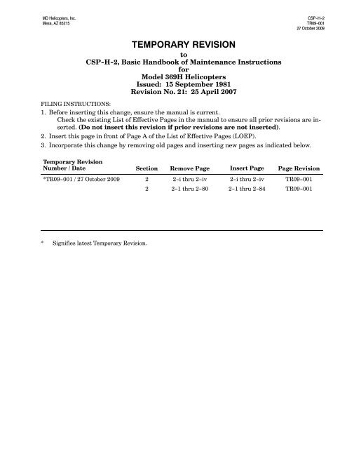
CSP−H−2<strong>MD</strong> <strong>Helicopters</strong>, Inc.500 Series − Basic HMI26.33 FT.(8.025 M)5.06 FT.(1.542 M)4.57 FT.(1.393 M)30.30 FT. (9.235 M)21.25 FT. (6.477 M)23.00 FT. (7.01 M)15.00 FT. (4.572 M)7.00 FT.(2.134 M) 6.30 FT.(1.92 M)4.25 FT.(1.295 M)8.50 FT.(2.591 M)8.20 FT.(2.499 M)7.20 FT.(2.195 M)0.79 FT.(0.241 M)NOTE:ADD 0.63 FT. (0.19 M) TO ALL VERTICAL DIMENSIONSIF EXTENDED GEAR IS INSTALLED.6.80 FT.(2.073 M)30−002DFigure 2−1. Principal DimensionsPage 2−2TR09−001
<strong>MD</strong> <strong>Helicopters</strong>, Inc.500 Series − Basic HMICSP−H−22. Helicopter FundamentalsA. Principal DimensionsPrincipal dimension are shown in Figure 2−1.B. Airframe Stations LocationsReference is occasionally made to ‘‘station" and‘‘waterline" throughout the handbook. To assistin locating the components being discussed,refer to the station diagram provided inCSP−H−6. Station and waterline referencesare also necessary for weight and balanceprocedures.C. Component Weights for HoistingThe maximum weight for large componentsthat may require hoisting are listed inTable 2−1.Table 2−1. Approximate Maximum HoistingWeights of ComponentsItemWgtLb/kgTailboom 14/6Main Rotor Hub 58/26Main Transmission 79/36Engine (built up) 170/77Helicopter (less engine) 1000/455Helicopter (less main rotor hub,swashplate, scissors, and rotor blades) 998/453Helicopter (complete) 1170/5313. Helicopter Ground HandlingGround handling of the helicopter includeshoisting, jacking, leveling, parking andmooring. The following paragraphs present theinstructions and precautions for all groundhandling functions.A. Use of External PowerAn external receptacle is located at the rightside of the pilot’s compartment seat structure.The right door must be opened to use thereceptacle. Any source of external 28 volt,direct-current power may be connectedprovided the negative terminal of the plugmates with the negative terminal of thereceptacle and the amperage available issufficient. Engine starting requirements areapproximately 375 amperes minimum.Before connecting external power,make certain that the heli-CAUTIONcopter main electrical power selector switchis in the OFF position. After power is connectedto the receptacle, the power switchmust be at the EXT position to connect externalpower to the helicopter electrical system.NOTE: The positive (+) and negative (−) voltageterminals are clearly marked on the base ofthe receptacle to prevent reversing of polarityif a standard auxiliary power plug is notavailable.B. Hoisting(Ref. Figure 2−2) Observe the followingprecautions during any hoisting operation.Use a hoist of no less than 3500CAUTIONpound (1598 kg) capacity whenhoisting the complete helicopter. Use hoistingequipment of sufficient capacity (minimumtwenty-percent over-rate) to hoist theheavier components if handled separately.(Ref. Table 2−1 for approximate weights.)(1). Install hoisting adapter (1, Table 2−2)on main rotor hub so that the fourhoisting eyebolts fit into the slots on thehoisting adapter.(2). Install the four clevis pins.(3). Attach cable from overhead hoist to theadapter eye.(4). Secure a line to the tailboom. Have anassistant hold the line to keep thehelicopter from swinging.(5). Hoist slowly and smoothly to maintaina steady lifting force.Page 2−3TR09−001
CSP−H−2<strong>MD</strong> <strong>Helicopters</strong>, Inc.500 Series − Basic HMILOCK PINFWD JACKING POINTBOTH SIDES (STA 96.9)JACKING FITTINGAFT JACKING PAD(STA 197.2)HOISTING ADAPTER(369A9904)CLEVIS PINS(4 PLCS)SAFETY PIN(EACH CLEVIS)HOISTING EYEBOLTS(4 PLCS)PLUMB LINESUPPORT CLIPRH EDGE OFCONTROLS TUNNELPLUMB LINETARGET PLATE30−004CFigure 2−2. Hoisting, Jacking and LevelingPage 2−4TR09−001
<strong>MD</strong> <strong>Helicopters</strong>, Inc.500 Series − Basic HMICSP−H−2C. Jacking(Ref. Figure 2−2) Provisions for jacking thehelicopter are provided by two forward (side)jacking point fittings and an aft jacking pad.NOTE: When the helicopter is jacked from oneside only, a cushioned saddle-type supportshould be placed under the tailboom at theboom jacking fitting location for extra stability.(1). Install jacking fittings (2, Table 2−2) inthe fuselage jacking points. Secure thejacking fittings with the locking pinsthat are secured to the fuel cell accessdoors.(2). Place suitable jacks under jackingfittings, and under aft jacking pad.(3). Raise the helicopter to the desiredheight.D. Leveling(Ref. Figure 2−2) Leveling is accomplished bycausing a plumb bob to intersect registermarks inscribed on the target plate located onthe cargo compartment floorNOTE: Access to plumb line support bracketand target plate on floor of passenger/cargocompartment requires removal of trim onright side of controls tunnel and floor carpetin aft compartment.(1). Suspend plumb line from bracket onright side of controls tunnel at Sta.92.64, BL +6.20.(2). Adjust plumb line swing to levelingtarget plate on floor of passenger/cargocompartment.(3). With weight of helicopter supported byload cells or jacks, adjust appropriatejack until plumb line is centered.(4). Adjust side jacks to level helicopterlaterally.(5). Adjust tailboom jack to level helicopterlongitudinally.(6). Recheck lateral and longitudinal levelsuntil the plumb bob exactly aligns withmarks on target plate.(7). After leveling helicopter, remove plumbbob, reinstall trim and carpet and closecompartment door.E. Parking(Ref. Figure 2−4) To park the helicopter forshort intervals, perform steps (1). thru (4). Forlonger duration parking, also perform steps(5). and (6).To prevent rotor damage fromCAUTIONblade flapping (droop stoppounding) as a result of air turbulence fromother aircraft landing or taking off, or suddenwind gusts, rotor blades should be securedwhenever the aircraft is parked.(1). Locate the helicopter slightly more thanblade clearance from near−by objects.(2). Apply friction to lock the cyclic stick sothat the friction control knobs arepositioned on the lateral and longitudinaltravel stop guides as follows:neutral laterally (center of slot), andone−third from full aft longitudinally(one−third up from bottom of slot).NOTE: If not all ready accomplished, apply apaint mark on the edge of the guide to locatethe neutral position for future reference.(3). Locate the helicopter on the most levelground available.(4). Secure the main rotor blades as follows.(a). Turn blades until they are at 45degrees angle to the fuselage centerline.(b). Install blade socks (3, Table 2−2) onall blades.When securing tiedown cords,CAUTIONtake up slack but do not exertbending loads on blades.(c). Secure blade sock tiedown cords tofuselage jacking fittings.(5). Install engine air inlet cover assembly(46 on engine air inlet front fairing.(6). Install engine exhaust outlet cover (47)on exhaust tailpipes.F. Mooring(Ref. Figure 2−4) Whenever severe stormconditions or wind velocities higher than 40Page 2−5TR09−001
CSP−H−2<strong>MD</strong> <strong>Helicopters</strong>, Inc.500 Series − Basic HMIknots are forecast, the helicopter should behangared or evacuated to a safer area. If theseprecautions are not possible moor the helicopterin the following manner.(1). Park helicopter and remove main rotorblades and install engine inlet andexhaust covers.(2). Install pitot tube cover (4, Table 2−2).(3). Fill fuel tank (if possible).(4). Apply friction to lock the cyclic andcollective sticks.(5). Secure the helicopter to the ground byattaching restraining lines (cable orrope) between the jacking fittings andstakes or ground anchors.G. Ground Handling Wheels(Ref. Figure 2−3) Standard ground handlingwheels, available as a special tool (6,Table 2−2), are used for moving the helicopter.The handling wheels consist of two, two−wheeled jacking assemblies that can bestraddle−mounted to the left and right landinggear skids by use of the existing groundhandling wheel fittings. The wheels aremanually lowered with detachable jack handle.Either the straight handle (7) or the offsethandle (8) may be used depending on clearancerequirements. The wheels are held in downposition (helicopter raised on wheels) by amechanical lock. The wheels are equipped withtow bar attach fittings. Attach the groundhandling wheels as follows:NOTE: Special optional ground handlingwheels (5) are used for moving the helicopterwhen equipped with option emergencyfloats (Ref. CSP−H−3). If helicopter with extendedgear is tilted back on the tail skid toinstall ground handling wheels, approximatelyone pint of oil is trapped in the tailrotor gearbox. This condition will give afalse sight gage oil level indication after returnto a level attitude. The oil will return tonormal after ground runup.(1). Position ground handling wheelassembly over the skid tube at thelocation of the skid fitting.(2). With ground handling wheels in theretracted position, align and engage theskid fittings.(3). Install jack handle in the wheelassembly socket, install lock pin, androtate handle downward to lower thewheels and raise the helicopter.Hold downward pressure onWARNING jack handle until the extendlock snaps into lock position. If the lockis not properly engaged and the handleis released, the upward swing of thehandle could cause serious personal injury.(4). Check that the extend lock is engaged;then release downward pressure andremove jack handle.(5). Install second ground handling wheelassembly in the same manner.(6). At regular intervals, the groundhandling wheels tire pressure should bechecked for 80−90 psi (552−621 kPa)and the wheel bearings lubricated withgrease (18, Table 2−4).H. Helicopter Moving and Towing(1). Manually move the helicopter onground handling wheels by balancingthe tail boom and pushing on the rearfuselage portion of the airframe.The helicopter should always beCAUTIONtowed at slowed speeds, not over5 mph, except in extreme emergency conditions.Do not allow the front end of the skidtubes to drag on the ground. Avoid suddenstop and starts, and short turns which couldcause the helicopter to turn over. Allow theinside wheels to turn (not pivot) while thehelicopter is being turned. The proper minimumturning radius is approximately 20 ft.(6 M).(2). Towing the helicopter on groundhandling wheels by attaching a suitabletow bar to the two bar fittings. If thetow bar is not equipped to keep thefront ends of the skid tubes fromdragging, have an assistant balance thehelicopter at the tail boom.Page 2−6TR09−001
CSP−H−2<strong>MD</strong> <strong>Helicopters</strong>, Inc.500 Series − Basic HMITable 2−2. Ground Support Equipment and Special ToolsNOTE: Most of the equipment and tool items in this table are used to support and maintain all configurations of the369H helicopter, except when an asterisk symbol ( * ) is part of the item number to indicate limited use. Limitedapplications noted in the Application or Use column. Special tools used only for major disassembly-repairand/or overhaul of components are listed in applicable section of CSP−H−3. See end of table for explanationof deltas and daggers.ItemPart No. Nomenclature Application or UseNo.1 369A9904−501 Hoisting adapter Hoisting entire helicopter or removing mainrotor.2 369A2010 Jacking fittings Jacking, leveling or tie down of helicopter.3 369D2661 Blade socks Main rotor blade tie downs.4 369H4009 Pitot tube cover Pitot tube protection.5 369H90126 Ground handling wheels(one side)6 369A9905 Ground handling wheel(one side less handle)7 369H9801 Handle−Jack assembly groundhandling (straight)8 369A9906 Handle−Jack assembly, groundhandling (offset)Ground handling of helicopter equipped withutility or emergency floats. (Ref. CSP−H−3)Ground handling of helicopter.Raising and lowering helicopter with groundhandling wheels.Raising and lowering helicopter with groundhanding wheels when addition clearance isrequired.9 369H9925 Collective rigging fixture Rigging of main rotor collective controls(369HE and 369HS only).10 369A9927 Collective rigging fixture Rigging of main rotor collective controls(369HM only).11 369A9930 Mixer rigging plate Rigging of main rotor collective and cycliccontrols.12 369A9929−9 Longitudinal rigging fixture Rigging of main rotor cyclic controls (369HEand 369HS only).13 369A9929−5 Longitudinal rigging fixture Rigging of main rotor cyclic controls (369HMonly).14 369A9928−9 Lateral rigging fixture Rigging of main rotor cyclic controls (369HEand 369HS only).15 369A9928−5 Lateral rigging fixture Rigging of main rotor cyclic controls (369HMonly).16 369A9926−7 or369A9926−5 (1)Main rotor blade tracking high intensitystrobe light installation and assemblyTracking of main rotor blades.17 369A9958 Main rotor blade tab bending tool Adjusting main rotor blade tab angle forblade track.18 369H9928 Main rotor blade tab bending tool Adjusting main rotor blade tab angle forblade track.19 369A9934−601(replaced by 21)Main rotor mast nut wrenchLoosening/Torquing of main rotor mast nut.Page 2−8TR09−001
<strong>MD</strong> <strong>Helicopters</strong>, Inc.500 Series − Basic HMICSP−H−2ItemNo.Part No.Table 2−2. Ground Support Equipment and Special Tools (Cont.)NomenclatureApplication or Use20 369A9934 Main rotor mast nut wrench Loosening/Torquing of main rotor mast nut(non−slotted mast only).21 369A9829 Main rotor wrench assembly Loosening/Torquing of main rotor mast nut.22 369A9932 Hub pullerBreaking loose main rotor hub from mast.369A9932 (2)23 369A9949 Torque wrench adapter Checking main rotor damper first stagefriction.24 369A9933 Main rotor hub driverSeating main rotor hub.369A9933−5 (3)25 369A9983 Torque wrench adapter Torque tailboom attachment bolts.26 369A9936 Bungee installation tool Holding collective bungee spring incompression for bungee removal andinstallation.27 369A9985 Bungee spring compression tool rodand channel28 369A9931 or Tail rotor swashplate rigging tool369A9931−3Removing bungee installation tool anddisassembling bungee spring assembly.Rigging of tail rotor controls (fiberglassblades).29 369A9931−5 Tail rotor swashplate rigging tool Rigging of tail rotor controls (metal blades).30 369A9937 Torque wrench adapter Installing tail rotor nut.31 369A9999 (4) Tail rotor balancing kit Strobe light analysis for balancing installedtail rotors.32 FRDH 101 Torque wrench adapter Installing main rotor drive shaft bolts andeyebolts.33 RXT20−5(extraction)RTM20−9(insertion)34 M8ND &N14HTCHYTIP insertion/extraction tool (mfg byBurndy, Norwalk, Connecticut)HYTOOL M8ND (catalog No. Y14MRC); Die−Sets N22PCT−1 & −2, andN14HCT (mfg: same as item No. 33)35 107−0970 Hand−operated crimping tool (CatalogNo. 107−0970) with positioners(Catalog No. 107−0976 and107−0977)(mfg by WinchesterElectronics, Division of LittonIndustries, Main St. and Hillside Ave,Oakville, Connecticut 06779)36 107R1001 and107−1015Removable contact removal tool(Catalog No. 107R1001) and insertiontool (Catalog No. 107−1015) (mfr:same as item No. 25)Installing and removing HYTIP electricalcontacts into and from terminal blockmodules.Manual crimping of MINILOK and MODILOKterminal block contact tips on electrical wireharness leads.Hand crimping of removable contacts inrectangular connectors.NOTE: Tool conforms to MS−3191−2(MIL−T−22520, Class 1).Removing and inserting removable contactsfrom and into inserts of rectangularconnectors.37 Deleted38 369A9948 Engine stand Support for removal or replacement engine.Page 2−9TR09−001
CSP−H−2<strong>MD</strong> <strong>Helicopters</strong>, Inc.500 Series − Basic HMIItemNo.Part No.Table 2−2. Ground Support Equipment and Special Tools (Cont.)NomenclatureApplication or Use39 369A8009 Engine hoist Removing and replacing engine in airframe.40 369A6001−50506−141 369A6001−50506−2Left landing gear foot drill jigRight landing gear foot drill jig42 CIET 20 Insertion/extraction tool, No. 20 WireMate connector (mfd. by I. T. T.Cannon Electric, 3208 Humbolt St.,Los Angeles, Calif. 90031)43 CIET 16 Insertion/extraction tool, No. 16 WireMate connector (mfr: same as No. 42)Enlarging holes in left lockbolt−type landinggear struts for installation ofmachine−bolt−attached skids.Enlarging holes in right lockbolt− typelanding gear struts for installation ofmachine−bolt−attached skids.Connecting and disconnecting No. 20 WireMate electric connectors.Connecting and disconnecting No. 16 WireMate electrical connectors.44 369A9822−5 Locknut torque wrench adapter Installing and removing tail rotorswashplate−to−control housing bearing nut.45 369A9922−3 Pitch control assembly holding block Holding tail rotor swashplate while removingand installing nut.46 369H9803 Engine air inlet cover Covering for engine air inlet front fairing.47 369H9804 Engine exhaust outlet cover Covering for engine exhaust tailpipes.48 369A1710−80901Fiberglass tail rotor blade, staticbalance moment fixtureDetermination of fiberglass blade staticbalance moment.49 369A9825 Pitch bearing stud wrench Removing main rotor hub pitch bearing pivotpin.50 369A9826 Stud nut wrench Holding main rotor hub pitch bearing pivotpin nut.51 369H9807 Main transmission drain hose Draining main transmission oil.52 2312−G Turbine temperature indicating systemtest set (Barfield Instrument Corp.)Test and calibration of the TOT indicatingsystem.BH112JA−36 Jetcal tester (Howell Instrument Inc.) Test and calibration of the TOT indicatingsystem.53 369A1600−8090254 83006−809−00090−155 83006−809−00090−1556 83006−809−00068Bushing wrenchArbor press fixture, 369A7951−5bearingStaking tool, 369A7951−5 bearingStaking tool, (pilot and punch), pitchcontrol assembly double row bearing369A7951−4557 WSI−HT−12AS Installation tool, WSI−B−12ASgrommet (mfd. by Western SkyIndustries, 21300 Cloud Way,Hayward, CA 94545)Installation and torquing tail rotor hubthreaded bushing.Installing bearing in tail rotor pitch controllink.Staking bearing in tail rotor pitch control link.Installing bearing and swage ring in pitchcontrol housing.Installing grommets for tail rotor control rod.Page 2−10TR09−001
<strong>MD</strong> <strong>Helicopters</strong>, Inc.500 Series − Basic HMICSP−H−2ItemNo.Part No.Table 2−2. Ground Support Equipment and Special Tools (Cont.)NomenclatureApplication or Use58 269A9232 Plug, 269A5050−18 bearing removal. Removing double−row bearing from tailrotor pitch control housing.59 Chadwick−Helmuth Balancer /Analyzer Instrument Kit60 369D29999 Main rotor and tail rotor balance sparekit61 830006−809−00090−862 830006−809−00090−20Arbor press fixture for 369A7951−15bearingStaking tool for 369A7951−15 bearingEquipment for tracking and balancing ofdynamic components. Main/Tail rotorvibration analyzer.Used with Item 59 to balance tail rotor andmain rotor.Installation of bearing in main rotor blade.Staking of bearing in main rotor blade.63 36−D−284 Prop protractor Measure angle of incidence.NOTE:(1) Main rotor blade tracking equipment 369A9926−7 and −5 each contain a strobe light 369A9925, magneticpickup 369A9944, one set of interrupters, a set of tracking cap reflectors and associated mountinghardware. The 369A9942−27, −29, −31 and −33 Tip Cap Assemblies are to be ordered as replacementfor the 369A9942−7, −9, −11, and −13 and the 369A9942−501 Tip Cap Assemblies.(2) Handle, frames and puller nut same as 369A9932; −31 thrust pad replaces −3 thrust pad.(3) Hammer and handle same as 369A9933; −7 driver −3 driver.(4) Tail rotor balancing equipment 369A9999 contains a vibration analyzer 369A9801, protractor assembly369A9979, acceleration mounting bracket 369A9920 and associated attachment and balancinghardware.Page 2−11TR09−001
CSP−H−2<strong>MD</strong> <strong>Helicopters</strong>, Inc.500 Series − Basic HMIBLADE SOCK(369H26661)(4 PLCS)OIL COOLER BLOWER/TRANSMISSIONCOOLING AIR INLET PLUGS (2 PLCS)TIEDOWN TETHERMOORING ANCHOR(4 PLCS)CABLE OR MANILA ROPEPITOT TUBE COVER(369H4009)ENGINE EXHAUSTOUTLET COVER(369H9804)AIR INLET FAIRINGCOVER (369H9803)ZIPPEREXTENSION SPRINGACCESSDOORLATCHLOCKPINFUEL CELL ACCESS DOOR(TYP − 2 PLCS)TIE CORDTO BLADESOCKTO MOORINGANCHORJACK FITTINGTO BLADE SOCKLOCKPIN STOWAGEFUSELAGE STRUCTUREJACKING FITTINGENGINE AIR INLET FAIRINGWITH COVER INSTALLED30−005Figure 2−4. Parking and MooringPage 2−12TR09−001
<strong>MD</strong> <strong>Helicopters</strong>, Inc.500 Series − Basic HMICSP−H−24. Servicing(Ref. Figure 2−5) Servicing of the helicopterincludes replenishment of fuel, changing orreplenishment of oil and other such maintenancefunctions. Fuels, oils, others servicingmaterials and capacities are listed inTable 2−3. Observe the following precautionswhen servicing the fuel system.Turn off electrical switchesWARNING and disconnect externalpower from the helicopter.(1). The helicopter must be electricallygrounded prior to refueling or defueling.The possibility of static discharge(difference in electrical potential) andpresence of fuel vapors always presentsfire and explosion hazards.(2). The refueling vehicle should be parkeda minimum of 20 ft. (6 M) from thehelicopter during the fueling operation.Before starting the fueling operation,always ground the fueling nozzle or fueltruck to the GROUND HERE receptacleor to another bare metal location.Use extreme care when applyingany type of lubricantCAUTION(grease, oil, dry−film, etc) in the vicinity ofteflon bearings. Most lubricant will form adirt retaining film or have other detrimentaleffects that can cause rapid detertioration ofbearing surfaces.A. Fuel System FillingThe fuel system has two fuel cells that areinterconnected for simultaneous flow venting.The fuel filler cap is on the right side of thehelicopter.(1). Refuel helicopter with correct fuel assoon after landing as possible toprevent moisture condensation and tokeep the helicopter as heavy as possiblein case of winds.(2). Keep fuel nozzle free of all foreignmatter.(3). Check filler cap for security afterfueling.B. Fuel System DrainingFuel draining should be accomplished withhelicopter as level as possible.(1). Fuel system may be defueled in eitherof two ways:To avoid possible damage to fuelCAUTIONpump, do not operate fuel pumpwith fuel tanks drained.(a). Defuel through filler port using apump.(b). Open system drain valves on fuselageunderside and in engine compartment.(2). Fuel supply line drain valves are springloaded type and open by pushing valveand attached drain line.(3). Fuel cells drain valve is spring−loadedclosed and is opened by pressinginternal plunger.C. Engine Oil System FillingThe engine oil filler cap is on the right side ofthe helicopter. A liquid level plug for checkingthe oil level in the tank is visible through atransparent window near the filler.NOTE: Before adding oil, the oil container mustbe shaken to ensure proper mixture of theanti−foaming additive. If sight gauge does not permit positive determination,remove filler cap and visuallycheck the oil level.(1). Check oil level within 15 minutes ofengine shutdown; replenish if low.(2). If engine oil level is low after helicopterhas set for more than 15 minutes;(a). Run engine for at least one minute atground idle.Ensure engine oil pressure is attainedwhen starting engineCAUTION(Ref. applicable Pilot’s Flight Manual).(b). Shut down engine, check oil level,replenish if low.Page 2−13TR09−001
CSP−H−2<strong>MD</strong> <strong>Helicopters</strong>, Inc.500 Series − Basic HMINOTES:1. SELF−CLOSING VALVE 50−60 IN. LB. (5.65−6.78 NM);CHIP DETECTOR (WITHOUT KNURLED DETECTORKNOB) 40−50 IN. LB. (4.52−5.65 NM).2. ENGINE LOWER CHIP DETECTOR 60−80 IN. LB.(6.78−9.04 NM).3. BREATHER−FILLER 45−55 IN. LB. (5.08−6.21 NM).ENGINE ACCESSORYGEARBOX DRAIN(NOTE 2)MAIN TRANSMISSIONDRAIN (NOTE 1)LIQUID LEVELPLUGOVERBOARD OILDRAIN LINEMAIN TRANSMISSIONFILLERLIQUID LEVELPLUGONE−WAY LOCKRESERVOIRBREATHER−FILLER(NOTE 3)LIQUID LEVELPLUGFUEL SUPPLY LINEDRAIN VALVEOIL SUPPLYDRAIN VALVEGROUNDRECEPTACLEFUEL SYSTEMFILLERENGINE OILTANK FILLERFUEL CELLSDRAIN VALVEEXTERNAL POWERRECEPTACLETAIL ROTORTRANSMISSION DRAIN(NOTE 1)30−006CNOTE: Motoring engine can draw oil from the oiltank to the gearbox, giving low oil levelindications. If engine oil level indicates a low conditionafter setting overnight, engine checkvalve may be leaking oil from tank to enginegearcase.(3). Ensure oil tank filler cap is securelytightened immediately after servicing.D. Engine Oil System Draining (with Sta.137.50 Bulkhead Drain Ports Installed)(1). Open engine access doors.(2). Place suitable container under engineoil tank drain and remove engine oiltank filler cap.(3). Remove engine oil tank drain cap.(4). After draining oil from tank, reinstallengine oil tank drain cap and oil tankfiller cap.Figure 2−5. Servicing Points(5). To drain residual oil from engineaccessory gearbox drain, remove wirelead and lower chip detector. Usesuitable container to catch oil. Checkthat detector O−ring is serviceable(replace if necessary); reinstall detector,torque to 50 − 60 inch−pounds (5.65 −6.78 Nm) and reconnect wire lead.E. Engine Oil System Draining (with DrainValve Installed)(1). Remove sound insulation from cargocompartment aft bulkhead right−handaccess door (Ref. Figure 2−6). Removethe right−hand access door.(2). Place a suitable container under theoverboard oil drain line where it exitsthe fuselage underside at the firewall.(3). Remove cap from oil tank filler. Pull outknurled spring−loaded button to openvalve in engine oil drain line just belowcooler. Rotate button and valve poppetso that locking pin rest on shoulder ofpin slot.Page 2−14TR09−001
<strong>MD</strong> <strong>Helicopters</strong>, Inc.500 Series − Basic HMICSP−H−2(4). After draining the oil from the tank,reinstall the filler cap and close oildrain valve; ensure that poppet pin is instop slot.(5). Install access door and sound insulation.(6). To drain approximately 1/2 pint (0.23 L)of residual oil from engine accessorygearbox drain (Ref. Figure 2−5) removethe wire lead and the lower chipdetector. Use a suitable container tocatch the oil. Check that detectorpacking is serviceable (replace ifnecessary), reinstall detector, torque to50 − 60 inch−pounds (5.65 − 6.78Nm), and reconnect wire lead.F. Engine Oil System FlushingThe following procedure is for flushing oil thatas been contaminated or when changing thetype of oil.(1). Drain oil from engine, oil tank and oilcooler (Refer to Engine Oil SystemDraining).(2). Replace engine oil filter(s) (Ref. AllisonOperation and Maintenance Manual)(3). Refill engine oil system (Refer to Filling− Engine Oil System).(4). Operate engine for five minutes, shutdown and repeat steps (1). thru (3).G. Main Rotor and Tail Rotor TransmissionFillingTransmission (gearbox) oil should be replacedwith new oil whenever it is drained from thegearbox.NOTE: Inspection of internal ring gear bolts isrequired after oil is drained from the mainrotor transmission, at intervals specified inCSP−H−4, before refilling with oil.(1). Check transmission oil level in liquidlevel plug.(2). Replenish with correct oil until thelevel reaches FULL on the plug.(a). Fill main transmission by liftingbreather−filler cap and insertingspout of oil can into opening. Checkthat spring−loaded cap closes whenoil can spout is removed.(b). Fill tail rotor transmission by removinglockwire, unscrewing breather−filler and pouring oil into transmission.Check that filler O−ring isserviceable (replace if necessary),reinstall breather−filler and torque to45 − 55 inch−pounds (5.08 − 6.21Nm); secure with lockwire.NOTE: Breather−filler plugs that have thethreaded insert are installed with thebreather hole rearward.H. Main Rotor Transmission Draining(1). If installed, remove circular drain coverplug and padding for main transmissionfrom forward underside of transmissioncover panel. Otherwise remove,in order, sound insulation, gearboxaccess cover, transmission drainassembly and main transmission cover).(2). Position a suitable (min. 4 qt/4 L)container under main transmissiondrains or drain current configurationtransmission using transmission drainhose (41, Table 2−2).NOTE: Two types of chip detector are installedon the main transmission. The current typechip detector have a knurled knob to removeelectrical chip detector probe. Hand−tightenknob when reinstalling.(3). Remove wire leads, lockwire, chipdetector and self−closing valves.NOTE: The self−closing valve need not be removedif special drain hose is used. Inserthose fitting and turn to drain oil.(4). If damaged, replace O−rings used withchip detector and self−closing valves.(5). After oil has drained, install self−closingvalve and chip detectors. Torquechip detector,without the knurled chipdetector probe knob, 40 − 50 inch−pounds (4.52 − 5.65 Nm). Lockwirevalve to gearbox and detector to valve.Reconnect wire leads.(6). If used, reinstall padding and circulardrain cover plug on forward undersidePage 2−15TR09−001
CSP−H−2<strong>MD</strong> <strong>Helicopters</strong>, Inc.500 Series − Basic HMItransmission cover panel. Otherwise,reinstall, in order, the main transmissioncover, the drain assembly, the maingearbox access cover and the soundinstallation.NOTE: If equipped with a metal filter, the maintransmission filter should be cleanedwhenever the oil is drained. If equipped with a paper filter, the maintransmission filter should be replacedwhenever the oil is drained.I. Main Rotor Transmission Oil SystemFlushingThe following procedure is for flushing oil thatas been contaminated or when changing thetype of oil.(1). Drain oil from transmission and oilcooler (Ref. Main Rotor TransmissionDraining).(2). If equipped with a metal filter, cleanthe transmission oil filter (Ref. TransmissionLubrication Pump Oil FilterCleaning). If equipped with a paperfilter, replace the filter.(3). Refill transmission oil system (Ref.Main Rotor Transmission and TailRotor Transmission Filling).(4). Operate aircraft for five minutes, shutdown and repeat steps (1). thru (3).J. Tail Rotor Transmission Draining(1). Position suitable container under thetail rotor transmission drain.(2). Remove wire lead, lockwire, chipdetector and self−closing valve(3). If damaged, replace packings used withchip detector and self−closing valve.(4). After oil has drained install self−closingvalve and chip detector. Lockwire valveto gearbox and detector to valve.Reconnect wire lead.(5). Wipe dry any oil spillage with a cleancloth moistened with solvent (1,Table 2−4).K. Tail Rotor Transmission Oil SystemFlushingThe following procedure is for flushing oil thatas been contaminated or when changing thetype of oil.(1). Drain oil from tail rotor transmission(Ref. Tail Rotor Transmission Draining).(2). Refill tail rotor transmission (Ref. MainRotor Transmission and Tail RotorTransmission Filling).(3). Operate aircraft for five minutes, shutdown and repeat steps (1). and (2).L. One−Way Lock Control system Servicing(1). To check oil level, remove control accesscover.NOTE: Reservoir should be 1/2 to 3/4 full.(2). If oil level in reservoir is low, lift fillercap and add oil as needed.(3). Reinstall pilot’s seat cover.NOTE: If oil level is consistently low, one−waylock should be repaired to stop oil leakage(Ref. Component Overhaul Manual). Hydraulic fluid leakage from any part ofone−way lock is not permissible. Whenleakage is observed, assembly should beoverhauled (Ref. Component OverhaulManual) as required and a serviceableunit installed. If leaking one−way lock isnot replaced when leakage occurs, continuationin service may result in mechanicalmalfunction that could be hazardousto flight safety.Page 2−16TR09−001
<strong>MD</strong> <strong>Helicopters</strong>, Inc.500 Series − Basic HMICSP−H−2ItemNo.Table 2−3. Component Servicing and MaterialsComponent Capacity Material1 Tail Rotor Transmission (1)(2)(5) 0.5 U.S. Pt. (0.23 Liter) MIL−L(PRF)−23699 (3)Mobil Oil SHC 626 (3)(6)2 Main Transmission 4 U.S. Qt (3.78 L) Refer to Item 13 Engine Oil Tank (4) 3 U.S. Qt (1.32 L) Refer to Allison EngineOperation and MaintenanceManual4 Fuel Cells5 Standard nonself−sealing cells Capacity 64.0 U.S. Gal. (242 Liters)(416.0 pounds)6 Usable 62.1 U.S. Gal. (235 Liters)(403.5 pounds)7 Optional self−sealing cells Capacity 62.0 U. S. Gal. (234 Liters)(402.0 pounds)8 Usable 59.9 U.S. Gal. (226.8 Liters)(389.5 pounds)Refer to AppropriatePilot’s Flight ManualRefer to AppropriatePilot’s Flight ManualRefer to AppropriatePilot’s Flight ManualRefer to AppropriatePilot’s Flight Manual9 Overrunning Clutch −11, −21, −31 1.52 U.S. Oz. (45cc) MIL−L (PRF)−23699 (3)10 −41, −51 1.01 U.S. Oz. (30cc)11 One−Way Lock 0.67 U.S. Oz. (20 cc) MIL−H−560612 Battery (Nicad) As required MS36300 or 0−B−41Distilled WaterNOTES:(1) Oils approved for use in <strong>MD</strong>HI 369 Series Helicopter main and tail rotor transmissions are syntheticcompounds having Ryder Gear Value in excess of 2500 pounds.(2) Not a preferred lubricant for <strong>MD</strong>HI transmissions. Use MIL−L−7808 lubricating oil in transmissions onlywhen other oils listed are not available.(3) Approved for use above −40°F (−40°C).(4) For Model 250 Series engine oil change requirements and restrictions on mixing oils, refer to AllisonCommercial Service Letters.CAUTION: Mixing of oils within an oil series not in the same group is permitted only in an emergency. Useof mixed oils (oils not in the same group) in an engine is limited to five hours total running time. Adequatemaintenance records must be maintained to ensure that the five hour limit is not exceeded. Mixing of oilsfrom different series is not permitted.(5) Listed is the basic Military Specification only. Check the specification sheet for the latest alpha changeletter to determine whether the materials being used conform.(6) Mobil oil SHC 626 can be formulated such that it may have two different colors. The oil can still be mixedwith no adverse effects.Page 2−17TR09−001
CSP−H−2<strong>MD</strong> <strong>Helicopters</strong>, Inc.500 Series − Basic HMI5. Battery Handling and ServicingPrecautionsThe electrolyte used in nickel−cadmiumbatteries con-WARNINGtains potassium hydroxide, a casuisticchemical agent. Serious burns will resultif the electrolyte contacts skin. Explosivegases may be released from thebattery during charging. Before removingthe battery from the helicopter,make sure that the power selectorswitch is in the OFF position. Removalor installation of the battery connectorwhile the battery is under load may resultin explosions, electrical arcing orpossible severe personal burns.(1). Satisfactory battery operation is largelydependent upon proper operation of thehelicopter voltage regulator. Batteryproblems may often be prevented oreliminated by maintaining the voltageregulator setting at the precise voltagespecified.(2). Nickel−cadmium batteries contain anelectrolyte mixture of potassiumhydroxide and distilled water. Chemically,this is just the opposite of an acid.Take every possible step to keep thenickle−cadmium battery as far away aspossible from the lead−acid type ofbattery. Do not use the same tools andmaterials (screwdrivers, wrenches,syringes, gloves, apron, etc.) for bothtypes of batteries. Anything associatedwith the lead−acid battery, even the air,must never come in contact with thenickel−cadmium battery or its electrolyte.Even a trace of sulfuric acid fumesfrom a lead−acid battery may result indamage to the nickel−cadmium battery.(3). A low electrolyte does not necessarilyindicate that the water must be addedto the cells. The electrolyte level in thecell will vary, depending upon battery’sstate of charge.(4). During operation of the battery, somewater is lost from the electrolyte as aresult of normal gassing, venting, orovercharging. This loss should bereplaced with pure distilled water only;do not use potassium hydroxidesolution.(5). The state of charge of a nickel−cadmiumcan not be determined by eitherthe specific gravity of the electrolytenor the battery voltage. The specificgravity will remain the same whether ischarged are discharged or the electrolytemix contains potassium hydroxideor is contaminated with potassiumcarbonate. The voltage will not changeappreciably until the battery is almostcompletely discharged.(6). If sulfuric acid has been inadvertentlymixed with the electrolyte in thebattery, the upper areas of the cells willappear greenish in color. In such cases,the battery must be replaced.6. Battery ServicingBattery servicing consist of replenishing anyelectrolyte water that may have been lostthrough normal gassing, venting or over−charging. Lost water should be replaced withpure distilled water only. Never use potassiumhydroxide solution.The electrolyte level should beCAUTIONchecked only after the batteryhas been fully charged and then allowed torest (stand idle) for a period of two hours. Ifthe helicopter has operated continuously fora minimum of one hour or more, the batterymay be considered fully charged.(1). Turn power selector switch OFF.(2). Raise pilot compartment floor leftaccess door and remove battery cover.Use care to avoid damaging batterytemperature sensing wiresCAUTIONand switch connections during cleaning andservicing.(3). Wipe tops of cells with clean cloth andremove filler vent caps.(4). Check electrolyte level in each cell. Agage will be seen at the the bottom ofeach filler cavity. The gage may be arod, a ball, or an orange−colored stripwith two notches in the sides. Theelectrolyte level should be just abovethe rod or ball, or between the notchesin the orange stripe.Page 2−18TR09−001
<strong>MD</strong> <strong>Helicopters</strong>, Inc.500 Series − Basic HMICSP−H−2Do not add distilled water if theCAUTIONbattery has remained idle formore than two hours after flight (charging).The electrolyte level will drop in a longertime interval and any water would result inoverfilling.NOTE: If electrolyte level has lowered to the extentthat it is not visible, remove batteryfrom helicopter for bench charging and servicing.(5). Using a thoroughly clean bulb−typesyringe that has never been used forservicing a lead−acid battery, add puredistilled water as necessary to raise theelectrolyte 1/4 − 3/8 inch (6.35−9.525mm) above baffle (between level holesor above nylon rod gage, as applicable).If there is surplus electrolyte, replacethe battery or remove the battery andservice it in accordance with manufacturer’sinstructions.NOTE: If a battery with surplus electrolyte isserviced, it must be checked for serviceabilityaccording to manufacturer’s instructionsbefore reinstallation and reuse in the helicopter(6). Reinstall filler vent caps.(7). Reinstall battery cover, mountingscrews and washers; close and latchaccess door.7. Battery ChargingNickel−cadmium battery charging is accomplishedby either the normal charging methodor the deep−cycling method, depending uponthe circumstance. Normal battery chargingconsist of charging the battery by the constantpotential method or the constant currentmethod and adjusting the electrolyte level ifrequired. Normal battery charging is accomplishedwhen the need arises. Deep cyclingconsists of intentionally discharging and thenrecharging the battery, adjusting the electrolytelevel, checking the battery output capability(capacity discharge test), and again recharging.Deep cycling should be accomplished on anew battery before it is installed in thehelicopter, if required, and at the inspectionintervals specified in CSP−H−4. Deep cyclingshould also be accomplished after batteryrepairs such as replacement of individual cellsor the battery case, and after any idle period ofninety (90) days or more.NOTE: Follow the manufacturer’s operatinginstruction for the battery charger; however,all voltage values, discharge rates, andcharging schedules given (Ref. Battery DeepCycling) shall apply in event of conflict withthe constant potential battery chargerinstructions.A. Normal Battery ChargingReview the battery handlingWARNING and servicing precautions(Ref. Battery Handling and ServicePrecautions) before preforming the followingcharging operations.(1). If battery is installed in the helicopter,turn power selector switch OFF andremove battery.(2). Clean battery (Ref. Battery Cleaning).(3). Inspect battery for any damage thatwould require battery replacement orrepair.Do not add distilled water to theCAUTIONelectrolyte prior to charging,even if the electrolyte is not visible. Theelectrolyte level will raise as charging progresses.(4). Charge the battery as follows:NOTE: The following procedure provideinstructions for charging with the constantpotential method. When charging by theconstant charging method, disregard theprocedure in steps (a). and (b). below andcharge the battery according to battery andbattery charger manufacturer’s instructions.Charging is accomplished with cellfiller vent caps installed. Temperature ofbattery may rise during charging.(a). Using a constant potential charger,charge battery for 30 minutes takingcare to maintain a constant andaccurate charging voltage of 28.0 to28.5 Vdc for the full charging period.(b). If necessary, monitor and manuallyadjust charging voltage to preventany drop or rise in charging voltage.(5). Switch charger OFF and then disconnectbattery from charger.Page 2−19TR09−001
CSP−H−2<strong>MD</strong> <strong>Helicopters</strong>, Inc.500 Series − Basic HMI(6). Remove filler vent caps and checkelectrolyte level. Replenish with puredistilled water (Ref. Table 2−3) ifnecessary, taking care not to over−fill.(7). Replace and tighten filler vent caps.B. Battery Deep CyclingReview the battery handlingWARNING and servicing precautions(Ref. Battery Handling and ServicePrecautions) before preforming the followingcharging operations.(1). Perform normal charging (Ref. NormalBattery Charging).(2). Connect a 9 ohm resistance (9 ohm, 200watt−resistor or three 3 ohm, 75 wattresistors in series) across the batteryterminals and allow the battery todischarge for approximately 12 hours,or until the battery voltage decreasebelow one volt.(3). Remove 9 ohm load resistance frombattery and loosen cell filler vent caps.(4). Charge battery until charging dropsbelow 0.30 ampere.(5). While continuing to charge the batteryat a rate less than 0.30 ampere, use anaccurate voltmeter to measure thevoltage across the terminals of eachindividual battery cell. Each individualcell should be within 0.05 volt of the cellvoltage specified below for applicablecharging voltage.Charging Voltage(volts dc)Cell Voltage(volts dc)28.0 1.4728.1 1.4828.2 1.4828.3 1.4928.4 1.4928.5 1.50NOTE: Nominal individual cell voltage is 1.25volts for a normal, disconnected, fullycharged cell.(6). Switch charger OFF and then disconnectbattery charger.(7). Allow battery to rest for a minimum ofone hour maximum and a maximum of2 hours; adjust electrolyte level.(8). If electrolyte level is adjusted, reconnectbattery to charger and allow thebattery continue charging for thirtyminutes.If battery temperature exceedsCAUTIONroom temperature during initialcharging, battery temperature must be allowto decrease to room temperature beforerecharging the second time.(9). After allowing battery temperature todecrease to room temperature, repeatthe procedures described in steps (2).thru (8). above to cycle the battery asecond time.NOTE: When making the individual cell voltagemeasurement the second time, the voltageof each individual cell must measurewithin the voltage limits specified in step eabove. If the voltage of any individual celldoes not measure within the specified voltagelimits, the cell must be discarded. Replacea defective cell according to instructions.(10). Switch charger off and then disconnectbattery from charger.(11). Tighten cell filler vent caps.Page 2−20TR09−001
<strong>MD</strong> <strong>Helicopters</strong>, Inc.500 Series − Basic HMICSP−H−2ItemNo.MaterialTable 2−4. Maintenance MaterialsSpecificationNo. (1)1 Solvent, dry−cleaning P−D−680 (3)Commercial Products (2)Name/No.Mfr2 Lockwire (diameter asrequired)MS200995CCRES Safety wire(3)3 Sealing compound(color as noted)MIL−S−8802 890 Coast Pro SealMIL−S−8516Class II3C−3007Churchill Chemical Corp.Los Angeles, CAPR1422A1/2 Type IRTV 730Type IProduct ResearchDow CorningMidland, MI4 Primer MIL−P−85582 (3)5 Chromic Acid solution(pH 2.6 to 3.4):magnesium touch up(4) Dow #19 or equivalent Dow Chemical Co.6 Lacquer, acrylic(Fed−Std−595)7 Primer, catalyzed acrylic(yellow)<strong>MD</strong>M 15−1083 Black #17038Black #37038Parchment #20371Green #34151Blue #15102Blue #35044Brown #30140(Refer to item No. 6(3)8 Chemical film andchemical film materialsfor aluminum andaluminum alloys.MIL−C−5541B(Class 2, unlessnoted. Grade andtype optional.)Iridite 14−2Al−coatAlodine 1201Richardson Co.Allied−Kelite Products Division2400 E. Devon Ave.Des Plaines, IL9 Abrasive paper, siliconcarbide (grade as noted)P−P−101 (3)10 Surface cleaner(pre−painted solution withphosphoric acid base)TT−C−490 orMIL−C−10578,Type IIWO #1Turco Products, Inc.Wilmington, CAPage 2−21TR09−001
CSP−H−2ItemNo.Material11 Paint remover(acid type for epoxy)Paint remover(solvent type)<strong>MD</strong> <strong>Helicopters</strong>, Inc.500 Series − Basic HMITable 2−4. Maintenance Materials (Cont.)SpecificationCommercial Products (2)No. (1)Name/No.MfrTT−R−248 Turco 5851 #A202 Turco Products, Inc.Cee−Bee Chemical CompanyMIL−R−25134 (3)Plastic bead, spherical 20− 30 meshPoly Plus 20/30(6)Polyrock Co.4763 Murrita Ave.Chino, CA 91710Abrasive Cleaning Equip.20122 State Rd.Cerritos, CA 92701Abrasives Unlimited4653 S. 33 rd St.Phoenix, AZ 8504012 Thinner, acrylic−nitrocellulose lacquerMIL−T−19544Prepsol(Dupont 3919)E. I. DuPont Co.Los Angeles, CA13 Corrosion preventive,aircraft gas turbineengine, synthetic baseMIL−C−818814 Masking tape, pressuresensitiveUU−T−106 #216(High temp)3M Co.St. Paul, MN15 Protective coating MIL−C−6799Type 116 Tape, pressure sensitive,water−proof forpackaging and sealing(width and thickness asnoted)PPP−T−60Class I3M Co.17 Silicone adhesive/sealant18 Grease, oscillatingbearingMIL−S−8660B DC 4 Dow CorningG−624 SilasticGeneral ElectricSilicone Products DeptWaterford, NYMIL−G−25537 Aero Shell 14 Shell Oil Co.TG−4851Texaco Inc.19 Adhesive, epoxy,non−structuralMIL−A−52194Scotch−WeldEC 1838 (Part A&B)3M Co.Commercial A−1177−B B. F. Goodrich20 Abrasive cloth, aluminumoxide (grade as noted)P−C−451 (3)Page 2−22TR09−001
<strong>MD</strong> <strong>Helicopters</strong>, Inc.500 Series − Basic HMICSP−H−2Table 2−4. Maintenance Materials (Cont.)ItemSpecificationCommercial Products (2)MaterialNo.No. (1)Name/No.Mfr21 Grease MIL−G−81322 Mobil Grease 28 Mobil Oil CompanyAero Shell 22Braycote 622Shell Oil CompanyCastrol Industries1001 W. 31 st St.Downers Grove, IL 60515(630) 241−4000(800) 621−266122 Methyl−ethyl−ketone(MEK)TT−M−261 (3)23 Crocus cloth P−C−458 (3)24 Adhesive, silicone rubber Silastic 140 Dow Corning25 Lubricant, solid film MIL−L−8937MIL−L−23398HMS 4−1078Type I/XILubri−Bond 220(3)Molykote 3402(3)Kal−Gard AD(3)Pera−Silk G(3)Electro−film Inc.7116 Laurel Canyon Blvd.P.O. Box 106,No. Hollywood, CAProduct Techniques, Inc.511 E. 87 th Pl.Los Angeles, CAKal−Gard Coating & Mfg. Co.16616 Shoenborn StreetSepulveda, Ca. 91343Highway 52 N.W.West Lafayette, IN 4790626 Grease, aircraft andinstrumentMIL−G−23827 Braycoat 627 Bray Oil Company9950 Flair DriveEl Monte, CAAero Shell 7Exxon 5114EPShell Oil CompanyExxon Co.Houston, TX27 Acetone O−A−51 (3)28 Surface primer, lockingcompound (grade andform optional)MIL−S−22473 Locquic Loctite Inc.,702 No. Mountain Road,Newington, CT 0611129 Sealing, locking andretaining compounds;single component (gradeas noted)MIL−S−22473MIL−R−46082Loctite #35 or RC/609Loctite, Inc.30 Twine, nylon MIL−T−713 (3)Page 2−23TR09−001
CSP−H−2ItemMaterialNo.31 Insulation sleeving,electrical (vinyl tubing;size as noted)<strong>MD</strong> <strong>Helicopters</strong>, Inc.500 Series − Basic HMITable 2−4. Maintenance Materials (Cont.)SpecificationNo. (1)MIL−I−631Type F, FormU, Grade A,Class I,Category 1Commercial Products (2)Name/No.Mfr(3)32 Tape, pressure sensitive(width and thickness asnoted)33 Loctite remover (fordisassembled parts)34 Petrolatum(petroleum jelly)35 Lubricating oil, generalpurpose, preservative36 Antiseize compound,high temperature37 Lacing cord, hightemperature38 Dichloromethane(methylene chloride)39 Ethylene chloride(ethylene dichloride EDC)40 Gasket material(adhesive on one sideonly)41 Tape, pressure sensitiveadhesive, filamentreinforced42 Tape, pressure sensitivepolyurethane (width asnoted)43 Adhesive (epoxy),nonstructural44 Barrier material, greaseproofPPP−T−66Type I, Class AScotch Cal#471 VEFOakite 156VV−L−236 (3)VV−L−800 (3)MIL−A−907Type T−333MIL−D−6998 (3)MIL−E−10662 (3)Scotchfoam# 4304PPP−T−97 (3)MIL−B−121Type I, Gr A,Class 2MIL−B−131Class 13M Co.Oakite Product Inc.,Los Angeles, CAWarren Wire Co.3M Co.#Y8560 3M Co.Lefkoweld Type 109Resin/LM−52ActivatorLeffingwell Chemical Co.,Whittier, CA.45 Cement MIL−A−8576B PS−18 S147 Rohm and Haas Co.Swedlow, Inc.46 Tetrahydrofuran (THF) Foremost−McKesson Corp.Chemical Dept.Los Angeles CA(3)Page 2−24TR09−001
<strong>MD</strong> <strong>Helicopters</strong>, Inc.500 Series − Basic HMICSP−H−2ItemNo.Material47 Lacquer, clear, aluminumclad alloy surfaces48 Solder, tin alloy, rosincoreTable 2−4. Maintenance Materials (Cont.)SpecificationNo. (1)MIL−L−6066QQ−S−571(CompositionSN60WRP249 Emery cloth, fine (3)50 Patching material(inside/outside)(3)Commercial Products (2)Name/No.Mfr5187 Uniroyal, Inc.Fuel Container Dept.Mishawaka, IN51 Patching material5200 Uniroyal Inc.(outside only)52 Soap paste P−S−560 (3)53 Cheesecloth (3)54 Cement MIL−A9117 EC−678 3M Co.55 Solvent 3339 Uniroyal56 Vinyl tape and activator Tape: Scotch Cal#455 Activator:Scotch Title A−23M Co.57 Grease 130A Lubriplate Manufacturing58 Grease 930A Lubriplate Manufacturing59 Naphtha, aliphatic TT−N−95 (3)60 Sealant HT−461 1,1,1, Trichloroethane O−T−620 (3)technical inhibited62 Tape, aluminum foil # 425 3M Co.63 Detergent, general MIL−O−16791 (3)purpose64 Hydrofluoric Acid O−H−795 (3)65 Nitric Acid O−N−350 (3)66 Brazing flux, paste O−F−499 (3)67 Brazing alloy, silver base MIL−B−15395 (3)68 Tape, nitrile rubber NE−71A Armstrong Cork Co.Lancaster, PA69 Adhesive, bonding,vulcanized (syntheticrubber−to−steel)EC1300L3M Co.70 Corrosion preventivecompound, solventcutback, cold applicationMIL−C−16173Grade 3Braycote71 Isopropyl alcohol TT−I−735 (3)Bray Oil CompanyPage 2−25TR09−001
CSP−H−2<strong>MD</strong> <strong>Helicopters</strong>, Inc.500 Series − Basic HMIItemNo.Material72 Zinc chromate putty,general purpose73 Non−slip tape, pressuresensitive, medium grade(black)Table 2−4. Maintenance Materials (Cont.)SpecificationCommercial Products (2)No. (1)Name/No.MfrMIL−P−8116 Compound 3998 Fuller−O’Brien PaintsSanta Fe Springs, CAP−D−00455 (3)74 Electric tape, plastic MIL−I−7798 # 33 3M Co.75 Cleaning compound,alkaline waterbase76 Acetylene, technicalgradeMIL−C−25769BB−A−106 (3)77 Oxygen, industrial grade BB−O−925Type I, Grade B78 Welding rod, corrosionand heat resisting alloys(Class or type as noted)MIL−T−9821Bor CNitronic 40(3)21−6−979 Teflon tape # 520 Permacel# 48 3M Co.80 Use item 19Johnston Stainless WeldingRods13729 E. RosecransSanta Fe Springs, CA81 Fiberglass repair kit Cordokit RK−10 Ferro Corp.Composites Division34 Smith St.Norwalk, CT 0685282 Epoxy resin with catalyst,low pressure laminatingMIL−R−9300Type I83 Adhesive Epon 919 Shell Chemical Co.Pittsburgh, PA84 Fuel cell repair kit RK3CL Uniroyal85 Rod, welding QQ−R−566CLFS RA12 orRA143 (4043)5% silicon86 Solder, tin alloy, acid core QQ−S−571 (3)87 Insulation sleeving,electrical, fiberglass (sizeas applicable)(3)(3)MIL−L−3190 (3)88 Lubricant, solid film MIL−L−46010 (3)89 Tape, pressure sensitive(width as noted)4104 3M Co.90 Tape, double−faced E−706 Arno Adhesive Tapes Inc.,Los Angeles, CAPage 2−26TR09−001
<strong>MD</strong> <strong>Helicopters</strong>, Inc.500 Series − Basic HMICSP−H−2Table 2−4. Maintenance Materials (Cont.)ItemSpecificationCommercial Products (2)MaterialNo.No. (1)Name/No.Mfr91 Cement C−111 Sta−Bond Corp.Gardena, CA92 Adhesive, polyurethane U−136, (AC AAAA) Sta−Bond Corp.93 Tape #850 3M Co.94 Filler, resin Epon 960F Shell Chemical Co.95 Filler, resin #RP1257−3 Ren Plastics Inc.96 Rubber cement MIL−A−5092 (3)97 Preservative oil, hydraulic MIL−H−6083 Ref. Table 2−398 Grease GD 568−S GC Electronics,Los Angeles, CA99 Insulation varnish Glyptal 1201 General ElectricInsulation Dept.,Schenectidy, NY100 Vinyl plastic tape #330 Technical Tape Co.New Rochelle, NY101 Rust inhibitor spray(aerosol)102 Adhesive MIL−A−46106,Type I103 High temperature tape(thickness as noted)WD−40RTV732Temp−RRocket Chemical Co.,Inc., San Diego, CADow Corning Corp.Insulectro Co.1410 W. OlympicLos Angeles, CA104 Corrosion preventive oil Steelgard 1301 Harry Miller Corp.Philadelphia, PA105 Use item 17106 Sealant #5220 Fiber−Resin Corp.170 W. Providencia Ave.Burbank, CA107 Epoxy coating Poly−EP Detroit Graphite Co.Detroit, MI108 Thinner (for item 107) Poly−EP Detroit Graphite Co.109 Primer Resin (paint basefor polycarbonate plastic)Q−881Bee Chemical CompanyGardena CA110 Thinner (for item 109) T−80679 Bee Chemical Co.111 Graphite, powdered (3)112 Tape Temp R Tape(Type TV)113 Parting agent Fre−Kote 33 Fre−Kote Inc.Connecticut Hard Rubber Co.New Haven, CT114 Slip−Spray E. I. DuPont Co.Los Angeles, CAPage 2−27TR09−001
<strong>MD</strong> <strong>Helicopters</strong>, Inc.500 Series − Basic HMICSP−H−2Table 2−4. Maintenance Materials (Cont.)ItemSpecificationCommercial Products (2)MaterialNo.No. (1)Name/No.Mfr135 Plastic steel Devcon A Devcon Corp.Danvers, MA 01923136 Tape, pressure sensitive #471 3M Co.137 Molybdenum disulfide MIL−L−7866powder, lubricant138 Tape, pressure sensitive − − #4508 3M Co.(dimensions as noted)139 Spray lubricant − − Moly−Dee Arthur Withrow5511 District Blvd.Los Angeles, CA140 Adhesive primer HMS 16−1069 Liquid primer<strong>MD</strong>HIClass I141 Fluorocarbon release6611NE.I. DuPont Co.agent, dry film lubricant142 Sealer HMS 16−1068 EA9313 Hysol DivisionDexter Corporation143 Lubricant LPS3 LPS Research laboratories Inc.2050 Cotner Ave.Los Angeles, CA144 Cement Grip Talor IndustriesCity of Industry, CA145 Catalyst reducer 1−1H−75 Advance Coating and Chemicals146 Metal protector, aerosol Molykote Dow Corning Corp.147 Wash primer MIL−C−8514 (3)148 Enamel, epoxy(Fed−Std−595)<strong>MD</strong>M 15−1100Type IIBlack #37038White #37769Tan #20318Parchment #20371Red #11958Green #34151Gray #36231Yellow #13655149 Lubricant, spray Tri−Flow Costa Mesa LubricantP.O. Box 125Olive Branch, MS 38645150 Washing compound withwaxZip Wax (2)(3)Turtle Wax Inc.5565 W. 73 rd St.Chicago, IL 60638151 Sealant RTV106 (2) General Electric152 Tape CT93C Jones Industrial SupplyCulver City, CA153 Tube, silicone No. 4(H.A.I.)Varflex Corp.Rome, NYPage 2−29TR09−001
CSP−H−2<strong>MD</strong> <strong>Helicopters</strong>, Inc.500 Series − Basic HMITable 2−4. Maintenance Materials (Cont.)ItemSpecificationCommercial Products (2)MaterialNo.No. (1)Name/No.Mfr154 Sleeve, vinyl No. 2ResinateBorden ChemicalCompton, CA155 Thread sealant P412 Permacel156 Epoxy cement Hughes HP16−1 Type IIDow Corning Corp.EC 1300L157 Dry lubricant MIL−L−46010A EcoalubeNo. 642158 Leak detector, liquid MIL−L−25567C Leak−TecType I159 Fiberglass cloth,0.022, 2 ply160 Polyester laminatingresin161 Sealing compound,siliconeMIL−C−9084No. 181Everlube Corp.North Hollywood, CAAmerican Gas and Chemical Co.Cresskill, NJ(3)MIL−R−7575 (3)RTV11General Electric162 Dykem, red of blue SP1100 Dykem Company8501 Delport Dr.St. Louis, MO 63114163 Tape, duct (3)164 Xylene (3)165 Adhesive A−4000 Dow Corning Corp.166 Primer A−4004 Dow Corning Corp.167 Catalyst xy22 Dow Corning Corp.168 Adhesive, epoxy,non−structuralEC2216 2 PartResin: B (White)Activator: A (Gray)3M Co.169 Adhesive Stabond G−304 Sta−Bond Corp.170 Varnish, moistureresistantMIL−V−173Type II171 Sealing compound MIL−S−81733 PR−1431 Type IVPR−1436G Type II−2PR−1436GB−2(3)Product Research172 Cement Uniroyal #3230 Uniroyal Inc.Engineering Systems Dept.Mishawaka, Indiana 46544173 Repair kit, non−self−sealing cell174 Patch material, self−sealing cell, exterior175 Alcohol, denaturedType IO−E−760Uniroyal#RK−10−34Uniroyal #5241/5241sandwichPage 2−30TR09−001
<strong>MD</strong> <strong>Helicopters</strong>, Inc.500 Series − Basic HMICSP−H−2Table 2−4. Maintenance Materials (Cont.)ItemSpecificationCommercial Products (2)MaterialNo.No. (1)Name/No.Mfr176 Catalyzed epoxy primer Type I and Type II Advance Coating and Chemicals177 Pre−treatment MIL−P−15328 (3)178 Kit, dye penetrant MIL−I−25135 (3)179 Tape, pressure sensitiveY−9132−B3M Co.sponge rubber180 Adhesive, epoxyPart A & BEA9314181 Tubing, vinyl, clear PVC tubingSize 2 GAClear 105CSea Wire and Cable Inc.P.O. Box 647Madison, AL 357581−800−633−7210182 Release agent TC7−527 EDP Industries2055 E. 223 StreetLong Beach, CA 90810225 Ram Chemical Co.Gardena, CA183 Cleaner Desoclean 45 DeSoto Aerospace Coating, Inc.1608 4th. St.Berkley, CA 90621(818) 549−7823184 Adhesive HMS16−1149, T−5 Sta−Bond Corp.185 Dielectric compound DC4 Dow Corning Corp.NOTES:(1) Numbers are U.S.A. Specifications and Standards. Prefix symbols are defined as follows: AMS − AmericanMaterial Standard; MS − Military Standard; MIL − Military Specification; Single, double or triple alpha prefixof same letter − Federal Specification; AN − Air Force−Navy Aeronautical Standard; NAS − NationalAerospace Standard.(2) Primary selection. Any equivalent material may be used as an alternate selection.(3) Use best comparable grade material when conformity of available materials of same type with listedSpecification No. cannot be determined.(4) Several types of original protective treatment are used on magnesium alloy parts. With paint removed,treatment process should be identifiable from coating appearance as outlined in following table. Partsshould not be reprocessed either completely or partially without first contacting <strong>MD</strong>HI Customer ServiceDepartment. However, regardless of original process used, chromic acid brush−on treatment (Dow #19, orequivalent) is acceptable for touchup of coatings removed by abrasion, scratches or rework.(5) When ordering paint from Advance Coating and Chemicals, specify each paint by type (i.e., acrylic, epoxy,polyurethane), by color, and by AC part number. Also include compatible HS or Fed. Std. No. to ensure thatcorrect type and color paint is provided. The color code numbers for finish paints used on new Model 369helicopters are now being entered in helicopter log books prior to delivery of aircraft. Owners/operators ofearlier models should check sales order for paint numbers listed and enter them in some log books, orsales orders. If so, ensure when ordering Advance Coating paints that AC No. and SA No. are compatible.(6) Do not use over 50 psig air pressure for abrasive cleaning method. Mask or shield threaded areas orcritical surfaces where damage may result from abrasive blasting.Page 2−31TR09−001
CSP−H−2<strong>MD</strong> <strong>Helicopters</strong>, Inc.500 Series − Basic HMINOTE: (4) (Continued)Dow #1(Chrome Pickle)ProcessTable 2−4. Maintenance Materials (Cont)Applicable SpecificationMIL−M−3171, Type INormal CoatingThickness and ColorRemoves metal. Iridescent yellow or red;gray coatings are unacceptable.Dow #7 MIL−M−3171, Type III No dimensional change. Wrought orextruded parts − chestnut brown; castings− light brown to black; AZ91C−T6 andAZ92A−T6 alloys − gray.Dow #17(Anodize)Dow # 19(Chromic Acid Brush on Treatment)MIL−M−45202,Type I − light coatType II − heavy coatMIL−M−3171, Type VIClass C − 0.0002−0.0003; light green.Class D − 0.0002−0.0035; dark green.No dimensional change. Gray to Black.Page 2−32TR09−001
CSP−H−2<strong>MD</strong> <strong>Helicopters</strong>, Inc.500 Series − Basic HMI3 SCREWS, NUTS6 WASHERS4 BOLTS, WASHERSACCESS COVERCONTROLS TUNNEL COVERPILOT’S SEATCOVERAFT FAIRING16 SCREWS, WASHERSEARLY TYPECOLLECTIVE STICKCOVER2 SCREWS, WASHERS OR3 SCREWS, WASHERSLANDING LIGHT COVER3 SCREWS, WASHERSCURRENT TYPE5 SCREWS, WASHERSWIRING COVER17 SCREW, WASHERS(RIGHT HALF)15 SCREWS, WASHER(LEFT HALF)UPPER/LOWERCOLLISION LIGHTCOVER (TYP)CLOSURE(NOTE 1)SEAL(NOTE 2)NOTES:1. NOTE INSTALLED ON ALL HELICOPTERS.2. TAPE SEAL (42, TABLE 2−4).ENGINE AIR INLETFWD FAIRING4 SCREWS, WASHERS30−007−1EFigure 2−6. Access and Inspection Provisions (Sheet 1 of 6)Page 2−34TR09−001
<strong>MD</strong> <strong>Helicopters</strong>, Inc.500 Series − Basic HMICSP−H−2HEAL STRIPHINGE PIN, WASHERAND COTTER PINCLIPSPRINGLATCHCURRENT TYPEBEAMHINGEPIN (2)HINGEPINFWD FAIRINGPILOT’S COMPARTMENTFLOOR ACCESS DOOR (TYP)8 SCREWS, WASHERSHINGE PINAFT FAIRINGLATCHPLENUM CHAMBERACCESS DOORTURNLOCK FASTENERSTAIL ROTOR DRIVESHAFTACCESS DOORHINGE PINEARLY TYPEHANDLE (TYP)ACCESS DOORS(HINGE−MOUNTED)LATCHLATCHCARGO COMPARTMENT AFTBULKHEAD ACCESS COVER(TYP)FUEL FILLER SHIELD5 SCREWS,WASHERS2 SCREWS,WASHERS, NUTSGROMMET(NOTE 1)TURNLOCKFASTENERS30−007−2EFigure 2−6. Access and Inspection Provisions (Sheet 2 of 6)Page 2−35TR09−001
CSP−H−2<strong>MD</strong> <strong>Helicopters</strong>, Inc.500 Series − Basic HMIFUSELAGE STRUCTURESHIM PLATE(INDEX BEFORE REMOVAL)ENGINE ACCESSDOORCURRENT TYPEENGINE ACCESS DOOR HINGE(TYP 4 PLCS)PILOT,S AND CARGO DOOR HINGE(TYP 8 PLCS)HINGE PINEARLY TYPEBOOM BOLTS ACCESSDOORSTURNLOCKFASTENERSENGINE COMPARTMENT ACCESSDOORS LOWER LATCH(TAIL ROTOR CONTROLBELLCRANK) CONTROLACCESS DOORLEVER ASSYTURNLOCKFASTENERSFOOT SUPPORTFAIRING8 SCREWS,WASHERS(TYP)29 SCREWS,WASHERS(TYP)STRIKERCONTROLS ACCESS DOOR14 SCREWS, WASHERS OR27 SCREWS, WASHERS4 SCREWS,WASHERSENGINE COMPARTMENTACCESS DOOR LATCH(TYP)FUEL VENTCOVERCHANNELFOOT SUPPORT FAIRINGSECONDARY LATCHCHANNELFUEL CELLACCESS DOORSPRIMARY LATCH LEVER30−007−3EFigure 2−6. Access and Inspection Provisions (Sheet 3 of 6)Page 2−36TR09−001
<strong>MD</strong> <strong>Helicopters</strong>, Inc.500 Series − Basic HMICSP−H−2CARGO HOOK COVER6 SCREWS,WASHERSLOWER INSTRUMENTPANEL SUPPORTMOUNTING HOLE FORRUNNING TIME METER(LEFT SIDE ONLY)5 SCREWS,WASHERSINSTRUMENT PANEL LOWERSECTION SIDE COVER PANEL(TYP LEFT AND RIGHT SIDE)INSTRUMENT PANELLOWER SECTIONFRONT PANEL5 SCREWS,WASHERS12 SCREWSACCESS COVEREARLY TYPEMAST SUPPORTSTRUCTURETURNLOCKFASTENERSTAIL ROTOR DRIVEACCESS DOORCURRENT TYPE30−007−4EFigure 2−6. Access and Inspection Provisions (Sheet 4 of 6)Page 2−37TR09−001
CSP−H−2<strong>MD</strong> <strong>Helicopters</strong>, Inc.500 Series − Basic HMICURRENT TYPEGASKETCHIP DETECTOR ACCESSNOTE 3AIRFLOW BAFFLES(NOTE 5)MAIN TRANSMISSION COVER(NOTE 3)EARLY TYPEMAIN GEARBOXACCESS COVERBELT INSPECTIONFASTENERGASKETCHANNELMAIN TRANSMISSIONCOVER1 NUT, WASHERMAIN GEARBOXACCESS COVERNOTES: (CONT)3. SHADED AREAS REPRESENT FOAM GASKET SEALS.2 BOLTS, WASHERS;10 IN. LB. (1.13 NM) MAX.2 SCREWS4. COAT MATING SURFACES OF TRANSMISSION AND STRUCTURE WITH PARTING AGENT(112, TABLE 2−4). JUST PRIOR TO INSTALLATION, COAT SURFACES AND EDGES OF COVER(EXCEPT SEALS) THAT MATE WITH TRANSMISSION AND STRUCTURE WITH SEALING COMPOUND (105).5. PART OF 369A8063−505 COVER ASSY ONLY. (REQUIRED WITH 250−C20 ENGINE,)FASTENER30−007−5FFigure 2−6. Access and Inspection Provisions (Sheet 5 of 6)Page 2−38TR09−001
<strong>MD</strong> <strong>Helicopters</strong>, Inc.500 Series − Basic HMICSP−H−2TYPE B HOODINSTRUMENT PANELCENTER FAIRINGRETAINER(CURRENT TYPE)FASTENERS (NOT USEDFOR CURRENT TYPE)INSTRUMENT PANELLEFT SIDE FAIRINGTYPE A HOODFRESH AIR DEFLECTORVELCRO VIBRATION PAD(TYP)INSTRUMENT PANELRIGHT SIDE FAIRINGFASTENERS(SEVERAL TYPES USED)CANOPY PANEL ATTACHMENT(6 PLCS) (EITHER ACCORDION RIVETS ORHOOK AND PILE FASTENERS ARE USED)30−007−6CFigure 2−6. Access and Inspection Provisions (Sheet 6 of 6)Page 2−39TR09−001
CSP−H−2<strong>MD</strong> <strong>Helicopters</strong>, Inc.500 Series − Basic HMI(b). Install the two screws, two bolts andnut and washers that secure thedrain assembly to the structure,shroud and scroll.NOTE: Do not overtighten the two bolts andnut. Torque to 10 inch−pounds (1.13 Nm)maximum.(c). If drain assembly is a replacement,connect the flexible drain hose andsecure with two wraps to lockwire (2,Table 2−4).C. Main Transmission CoverDifferent main transmission covers are usedwith the shaft−driven and belt−driven oilcooler blower installations. The main transmissioncover is a polycarbonate plastic formthat essentially matches the transmissionhousing contour. The plastic form has apermanently bonded insulation blanket coverwith a fiberglass core and flexible vinylexterior. Plastic form gaskets cushion the coversurfaces that mate with the adjacent structure.When installed, there is space betweenthe cover and transmission to allow inlet airflow for transmission cooling. With theshaft−driven blower, a yoke−type drainassembly fits around the lower end of thecover. A flexible hose connects to the drainassembly outlet tube and pipes overboard anywater or oil that collects in the cover.(1). Removal (Shaft−Driven Blower):(a). Detach the main transmission drainassembly.(b). Release nylon tape edging (Velcrohook tapes) from mating nylon pilefasteners (Velcro piles) at aft edges ofcover.(c). Remove four screws and washersfrom cover.(d). Remove bolt from heater duct flangeat lower left aft inside corner of coverif heating system ducting is installed;then lower cover to remove it..(2). Inspection (Shaft−Driven Blower):Inspect foam gaskets and cover blanketfor deterioration and plastic cover forcracks.(3). Installation (Shaft−Driven Blower):(a). Position cover over transmission.(b). Install heater duct bolt at lower leftaft inside corner of cover if heatingsystem ducting is installed.(c). Install the four screws and washersfingertight. Check cover for proper fitand that liquid level plug is visible.(d). Tighten screws.(e). Set the nylon tape edging to themating file fasteners by using handpressure.(f). Attach the main transmission drainassembly.(4). Removal (Belt−Driven Blower):(a). Disconnect electrical wiring fromtransmission temperature sensor andchip detector.NOTE: The cover assembly may be installedwith sealant. To remove the cover, split thesealant with a sharp knife to protect sealsand surface finish from damage.(b). Remove 14 washers and screws toremove cover from fuselage structure,trim support strips and uppertransmission baffle.(c). Remove cover from left and rightcooling ducts.(5). Installation (Belt−Driven Blower):(a). Apply parting agent (113, Table 2−4)and sealant (106) to areas indicatedin Figure 2−6.(b). Position cover over transmission andinstall cooling ducts.(c). install 14 screws and washers tosecure cover and trim support strips.(d). Connect electrical wiring to transmissiontemperature sensor and chipdetector.Page 2−40TR09−001
<strong>MD</strong> <strong>Helicopters</strong>, Inc.500 Series − Basic HMICSP−H−2D. Main Transmission Cover AssemblySeals Replacement(Ref. Figure 2−7) Cover seals PN369H8063−85, 89, and −91 in the369H8063−505 polycarbonate type maintransmission cover assembly may be removedon a one time basis for inspection, andreinstalled using a rubber adhesive to ensureadequate bond between the seals and thepolycarbonate cover. This procedure, whichfollows, does not apply to 369H8097 fiberglasstype main transmission cover.(1). Remove main transmission coverassembly.(2). Remove 369H8063−85, −89 and −91rubber seals from cover assembly.Discard seal if any deterioration isnoted.(3). Use X−acto knife or equivalent toremove loose adhesive material adheringto polycarbonate cover and rubberseals. Use abrasive paper to removeremaining adhesive residue from coverand seals.(4). Abrade inside flange of rubber seals.(5). Wipe clean the abraded areas of coverand seals, using naphtha and cleancloth.(6). Apply adhesive (3, Table 2−4) to bothrubber seal and cover assembly. Alignseals and press into place.(7). Allow bond to cure for 24 hours;reinstall cover assembly.E. Cargo Compartment Aft Bulkhead AccessCoversThe cargo compartment aft bulkhead accesscovers enclose essentially symmetricalopenings to the fuselage spaces at either sideof the engine air inlet plenum chamber. Theright side cover provides access to the oil tank,oil cooler and oil system drain valve. The leftside cover provides access to elements of thecabin heating installation on the helicopters soequipped. Turnlock fasteners secure the outeredge of each cover to the fuselage.(1). Removal: Release turnlock fastenersand lift cover from structure.(2). Inspection:(a). Inspect turnlock fasteners andreceptacles for condition.(b). Inspect cover for corrosion andcracks.(3). Installation: Position the cover over theopening in the structure and engage theturnlock fasteners.369H8063−85 SEAL369H8063−91 SEAL369H8063−89 SEALMAIN TRANSMISSIONCOVER ASSEMBLY30−216Figure 2−7. Main Rotor Transmission Cover Seals InstallationPage 2−41TR09−001
CSP−H−2<strong>MD</strong> <strong>Helicopters</strong>, Inc.500 Series − Basic HMIF. Pilot Compartment Floor Access DoorsEach of the two pilot’s compartment accessdoors are formed by two hinged aluminum orfiberglass panels, hinged at the forward edgeto the pilot’s compartment floor. A latch at therear secures each door in place. Two aluminumheel strips, on which two stainless steel skidsare bonded, are hinged and held in place overeach door by a spring. early type doors are asingle piece of fiberglass with heel stripsbonded in place and the forward ends of thestrips hinged to permit opening the doors.(1). Removal: Remove either floor accessdoor as follows.NOTE: The one−piece door is removed accordingto step (d).(a). Release the latch at the rear of thedoor.(b). Raise and hold up the rear of the heelstrips for access to the long hinge pinat forward end of door.NOTE: Heel strips may be removed for ease ofaccess by detaching springs from clips (orbrackets) on underside of strips and removinghinge pins attaching forward ends ofstrips to the anti−torque pedal mountingbracket.(c). Remove the long hinge pin securingforward edge of door to pilot’scompartment floor; remove door.(d). Remove one−piece access door byreleasing the flush−mounted latchand removing the two hinge pins thatsecure the door at the forward end.(2). Inspection:(a). Inspect doors for cracks and othervisible damage.(b). Check security of heel strip bonding.(c). As applicable, inspect hinges andhinge pins for damage.(3). Installation:(a). Position door and secure forwardedge to floor using a long hinge pin.(b). If removed, heel strips are reinstalledby inserting hinge pins throughbrackets on forward end of strip andantitorque pedal mounting bracketand connecting springs to clips orbrackets on underside of heel strips.Crimp or stake end of pins slightlyafter installation or use hinge pinssecured by a cotter pin as follows:1). Detach spring from clip or bracketon underside of each heel strip (notapplicable to early type one−piecepilot compartment floor accessdoor).2). Remove existing hinge pins securingforward end of heel strips.3). Install new hinge pins and secureend of each pin with washer andcotter pin. Direction of pinhead isoptional.4). Attach spring to clip or bracket onunderside of each heel strip, asapplicable.5). Check installation of new hingepins for discrepancies.(c). Position one−piece door and installhinge pins through hinges andantitorque pedal mounting bracket.G. Fuel Cell Access DoorsThe fuel cell access doors are stiffener−reinforcedaluminum plates that form a portion ofthe cargo floor. the left access door providesaccess to the fuel quantity transmitter (tankunit) and fuel shutoff valve and the fuel cellcover (for access to the engine start pump), aswell as the left fuel cell. A quick−release lockpin is secured with a 4 inch (10 cm) lanyard tothe outboard edge of each door. The pins retainthe removable jacking fittings that are used forjacking, parking and mooring the helicopter. Astud on the stiffener of current type doorsprovides an attachment point for floor cushionmaterial.These are stressed doors. TheCAUTIONhelicopter must never be flownwith either door removed.(1). Removal: Remove the 29 retainingscrews and washers and lift out door.Page 2−42TR09−001
<strong>MD</strong> <strong>Helicopters</strong>, Inc.500 Series − Basic HMICSP−H−2(2). Installation:(a). Position door over opening andsecure in place with retaining screwsand washers.(b). Stow quick−release lock pin in itshole.H. Controls Tunnel CoverFour tunnel−routed control rods exit thetunnel area through a cover mounted at thetop of the Sta. 78.50 canted frame. The coveror cover boots must be removed before any ofthe control rods are removed. The cover hasfour naugahyde boots, two of which are sewedtogether while the other two are individual. Allboots are secured to the cover with self−clinchingnylon straps.(1). Removal: The right− and left−sideengine air inlet forward fairings shouldbe removed for best access to thecontrols tunnel cover.(a). Remove the three screws, nuts, andsix washers, and the four bolts andwashers from controls cover.(b). Remove the cotter pin, nut, bolt andwashers that secure the upper end ofeach tunnel−routed control rod.Disengage the rods ends from thebellcranks.(c). Lift controls cover over rod ends.(2). Installation:(a). Place controls tunnel cover over thefour control rods, with double bootsection fitting over the two right−sidecontrol rods.(b). Attach each control rod end to itsbellcrank with bolt (head to left, twowashers, nut and cotter pin.(c). Install controls tunnel cover with thethree screws, nuts and six washersaft, and the four bolts and washersforward. Tighten bolts and screwsevenly.(d). If removed, reinstall right− andleft−side engine inlet fairings.(e). Check that control rods move freelyin the cover boots.I. Engine Air Inlet Forward FairingsAmbient air is directed to the engine and theengine oil cooler through the two removableforward engine air inlet fairings and the aftfairing that is riveted to the structure. Theengine inlet fairings are fabricated of glasscloth layers over polyurethane foam fillers.The forward fairing halves establish the mainair inlet duct. Each half contains a smallerduct on its inside leading edge that divertscooling air to the main transmission and oilcooler blower. The forward fairings provideaccess to the main rotor mixer controls and themain rotor mast, its base and supportingstructure.(1). Removal: A total of 32 screws withwashers secure the fairing halvestogether and to the structure. Eitherhalf may be independently removed orthe joined halves may be removed as anassembly. Two screws and washers jointhe halves at the center splice.(a). Remove screws and washers attachingforward fairing to fuselage.Remove forward fairing.(b). Remove two screws and washers atthe splice if it is necessary to separatethe two halves.(2). Inspection: Inspect the engine air inletfairings for structural damage. inspectfor cracked or frayed glass clothsurfaces and crushed fillers. Inspecttape seals on closures inside fairings fordeformation and damage.(3). Repair: Make general repairs to theengine air inlet fairings according toCSP−H−6. Replace the tape seals onclosures inside fairings with 0.25 x 0.50inch (6.35 x 12.7 mm) pressure−sensitivetape (42, Table 2−4), cut to lengthas required.(4). Installation:(a). Position engine air inlet fairings onfuselage and align attachment holes.(b). Install attaching washers and screwsin mounting flanges and throughsplice at top of left−side fairing, iffairing halves separated.Page 2−43TR09−001
CSP−H−2<strong>MD</strong> <strong>Helicopters</strong>, Inc.500 Series − Basic HMIJ. Engine Air Inlet Fairing Access DoorsAccess doors are provided on both the forwardand aft engine air inlet fairings. The right sideof the forward fairing contains the tail rotordrive shaft access door. The right side of theaft fairing contains a removable or hinge−mounted plenum chamber access door.(1). Removal: Remove screws and washersor release turnlock fasteners to take offdesired access door.(2). Inspection:(a). Inspect turnlock fasteners andreceptacles for proper fasteningaction.(b). Inspect fiberglass doors for structuraldamage such as cracked or frayedglass cloth surfaces.(c). Inspect the hinge−mounted door forstructural damage and loose ormissing latching mechanism hardware.(d). Check latching mechanism and doorhinges for proper operation andlocking capability.(e). Inspect seal installed around aftfairing door for security and condition.(3). Installation:Check that all areas of the airCAUTIONinlet and plenum chambers areclean and free of debris. check that all protectivecovers are removed. Engine damagewill result if these precautions are not observed.(a). Position door on fairing and installapplicable screws and washers orengage turnlock fasteners.(b). Close the hinge−mounted plenumchamber access door and ensure thatlocking mechanism locks in place.K. Aft Section Air Inlet (Tail Rotor Drive)Access DoorThe early type aft section air inlet (tail rotordrive) access door is hinge−mounted to the aftfuselage structure above the plenum chamberand is secured in place with turnlock fasteners.The current type access door is a flat coveron the mast support structure. Twelve screwssecure the access cover in place. When anengine air inlet vertical screen is installed, fiveof the cover screws with washers also retainthe front of the screen base. Primarily intendedfor access to the front end of the tailrotor shaft, the door/cover provides limitedaccess to the accessories mounted on the aftend of the main transmission.(1). Removal:(a). Remove engine air inlet forwardfairing.(b). Remove screws from cover or releaseturnlock fasteners to release door.(2). Inspection: Inspect turnlock fastenersand receptacles for proper fasteningaction. Inspect door for structuraldefects and door hinge for damage andoperation.(3). Installation:Check that all areas of the airCAUTIONinlet and plenum chamber areclean and free of debris. Check that all protectivecovers are removed. Engine damagewill result if these precautions are not observed.(a). Close access door and engage turnlockfasteners or position access coveron mast support structure and securewith screws (and five washers asapplicable to inlet screen).(b). Install engine air inlet forwardfairing.L. Controls Access Door and Foot SupportFairingsThe controls access door and the two footsupport fairings provide access to the forwardlanding gear struts and dampers, lowerelements of the underseal installation for theengine and flight control systems and portionsof the electrical wiring routed beneath thepilot’s seat structure. The foot fairings arefiberglass assemblies, each having two smallpolycarbonate plastic windows. the outboardwindows allow inspection of the forwardlanding gear damper assemblies without priorremoval of the fairings. The inboard windowsPage 2−44TR09−001
<strong>MD</strong> <strong>Helicopters</strong>, Inc.500 Series − Basic HMICSP−H−2are not for inspection by establish left−orright−hand interchangeability. The controlsaccess door is aluminum plate that providesprimary access to the lower end of the tunnel−routed flight control push rods in addition toother elements of the control system.The controls access door is aCAUTIONstressed door. The helicoptermust never be flown with this door removed.(1). Removal: Remove eight screws andwashers to release each foot fairing.Remove 14 screws and washers, or 27screws and washers as applicable, torelease controls access door.(2). Installation: Position controls accessdoor (bevel at lower right corner) or footsupport fairings and secure with screwsand washers.M. Pilot’s Seat CoverThe pilots seat cover is an aluminum alloypanel assembly with a honeycomb core. Theseat cover provides primary access to theupper elements of the underseat installation ofengine and flight control systems.(1). Removal: Remove 16 screws andwashers to release the pilot’s seat cover.Use all necessary precautions toCAUTIONprevent the possible entry of foreignobjects into the controls linkage exposedby removal of the cover. Unnoticed debrisin this area could jam or damage thecontrols when they are moved.(2). Installation: Check that there are noforeign objects present in the controlslinkage. Position pilot’s seat cover andsecure with screws and washers.N. Outboard (LH) Collective Stick Cover andWiring CoverThe two small covers installed at the left sideof the seat structure keep the left seat beltfrom fouling the aft end of the collective stick.They also shield the electrical wiring where itexits the seat structure and where it connectsto the auxiliary circuit receptacles mounted inthe left corner of the bulkhead.(1). Removal: Remove screws and washersto release either cover.(2). Installation: Check that there are noforeign objects in the area shielded bythe covers, position cover and securewith screws and washers.O. Fuel Vent CoverThe formed aluminum fuel vent cover providesaccess to the fuel cell vent system crossoverfitting that interconnects the forward topinboard corners of the two cells.(1). Removal: Remove four screws andwashers to release the fuel vent cover.(2). Installation: Check that area to becovered is clean. Position cover andsecure with screws and washers.P. Fuel Filler ShieldThe polycarbonate plastic fuel filler shieldprotects the right fuel cell filler extension frompossible damage from cargo impact, and alsocovers the cargo floor opening for the filler.(1). Removal:(a). Remove five screws and washers thatsecure the fuel filler shield base tothe cargo floor.(b). Remove the two nuts, screws andwashers that secure the shield tabsto the fuselage skin and fuel filler capto release the shield.NOTE: Use care not to dislodge or damage thesealing grommet (if installed) that fitsaround the extended range fitting openingin the shield.(2). Installation: Position the fuel fillershield and install the two screws,washers and nuts that secure the shieldtabs to the fuselage skin and fuel fillercap; do not tighten.NOTE: Check that extended range fittinggrommet (if installed) provides a tight sealbetween the shield and fitting. Replacegrommet if deteriorated.Q. Boom Bolts Access Doors and Tail RotorControl Bellcrank Access DoorThe forward and aft boom bolts access doorsprovide access to the bolts that secure thetailboom to the fuselage aft section. Thesedoors are also removed for access to performPage 2−45TR09−001
CSP−H−2<strong>MD</strong> <strong>Helicopters</strong>, Inc.500 Series − Basic HMIremoval and installation of the tail rotor driveshaft and/or tailboom (tail rotor blade angle)control rod and to check drive shaft damperfriction or replace the damper. The tail rotorcontrol bellcrank access door provides primaryaccess to the Sta. 142 bellcrank link betweenthe Sta. 100 tail rotor control rod and thetailboom control rod.(1). Removal: Release turnblock fastenersand lift boom bolts or controls accessdoor from fuselage.(2). Inspection: Inspect turnlock fastenersand receptacles for proper fasteningaction.(3). Installation: Position boom bolts orcontrols access door and engageturnlock fasteners.R. Exterior Lights CoversThree fuselage openings for exterior lights areclosed off by round aluminum covers. Informationon night lights is provided in CSP−H−3.S. Cargo Swing/Hook Fairing CoverThe well of the cargo swing/hook fairing isclosed off by a rectangular aluminum alloycargo hook cover. Information on the cargoswing and hook is provided in CSP−H−3.T. Instrument Panel FairingsThe three instrument panel fairings and hoodaround the instrument panel are moldedthermoplastic enclosures that shield the areafroward of the panel from direct sunlight andforeign material. Removal of the side fairingsprovides access to the shutoff valve controls,electrical and indicating system componentsand any optional avionics equipment mountedto the instrument panel and on the panelsupport structure.(1). Removal:NOTE: On helicopters equipped with a type Binstrument panel with full face hood, eightface attachment screws and two panel lightsknife splices must be disconnected beforehood removal. Ref. Sec. 17 for attachmentand disconnect points.(a). Remove hood attachment screws andwashers; remove hood.(b). Remove or release fasteners joiningthe two side fairings.(c). Detach side fairings from the canopystructure by releasing accordionrivets or velcro fasteners.(d). Disconnect and tag−identify electricalloads from light/switch and hornhousing; then remove center fairing.(e). If required, remove attaching hardwareand horn and light assemblyfrom center fairing.(2). Installation: Install the instrumentpanel fairings in reverse order startingwith the last fairing section removed.Refer to Section 19 for battery sensingand engine out warning horn equipment.U. Instrument Panel Lower Section SideCover PanelsThe two side cover panels that enclose thelower instrument panel support assemblystructure are aluminum alloy sheet. Removalof the covers provides access to wiring, tubingand the fuel shutoff control cable routedupward to the instrument panel, as well asparts of the tail rotor control torque tubeinstallation. Refer to applicable configurationsupplement for removal of instrument panellower section.(1). Removal: Remove five screws andwashers to release either side cover.NOTE: The running time meter is mounted inthe left side cover and the landing lightrelay is mounted on the right side cover ofhelicopters equipped with either or both ofthese options. For instructions or replacementof either item, refer to CSP−H−3.(2). Installation: Check that there are noforeign Objects present in the controlslinkage, position the cover(s) and securewith screws and washers.V. Instrument Panel Lower Section FrontCover PanelThe front panel inside the lower section of theinstrument panel support is aluminum alloy.Removal of the cover provides access toelectrical and avionics wiring at the lowerforward area of the instrument panel.Page 2−46TR09−001
<strong>MD</strong> <strong>Helicopters</strong>, Inc.500 Series − Basic HMICSP−H−2(1). Removal: Remove five screws andwashers to release the cover.(2). Installation: Position panel and securewith screws and washers.W. Pilot and Cargo DoorsThe two pilot doors and two cargo doors arebonded aluminum alloy frames containinglarge plastic windows. Current type doors areauto−latching (automatically latch) whenclosed. Early type doors are latched manually.The door latching mechanism consists of fourlatches, two lengths of wire−reinforced cablewithin housings and a latch rod. The doorhinges on each door are provided with quickremoval type ball−lock hinge pins. The doorsdo not incorporate jettison provisions.(1). Removal:(a). Open the door and individually pullthe hinge pins up and out by thetabs.(b). Hold door in alignment so thathinges do not bind and slide doorhinges from hinge sockets to removedoor.(2). Installation:(a). Lift door into position so that hingesare aligned and engage door hingeswith fuselage hinge sockets.(b). Hold door open and insert hinge pinsfar enough for the spring−loaded balldetent to emerge past the lower sideof the hinge socket. Close and latchthe door.X. Engine Access DoorsThe two engine access doors are stamped andbonded aluminum alloy structures that formthe fuselage contour below the aft sectionengine compartment. The hinge−mounteddoors are secured in the closed position bythree lever type, draw hook latches.NOTE: For removal of current type doors, donot attempt to remove hinge pivot bolts andspacers. Refer to Section 3 for disassemblyat hinge points and for all door maintenance.(1). Removal (Current Type): Release thethree latches to open access doors.Index mark the hinge, shim andserrated plate to the door structure.Remove the three engine access doorhinge attachment screws with washers.The forward screws are attached withnuts and the aft screws attach torivnuts.(2). Installation (Current Type): Positiondoor and temporarily install shim,serrated plate and attachment hardware.Align indexing marks on shim,serrated plate and hinge with those onthe door and then tighten the screws.Close and latch the doors and check forfirm fit with no deflection. If furtheradjustment is required.(3). Removal (Early Type): Release thethree latches to open access doors.Remove the pivot point attachinghardware from the door hinge and liftdoor from fuselage hinge halves.(4). Installation (Early Type): Lift accessdoor into position, align hinges andinstall attaching hardware. Close andlatch the doors and check for firm fitwith no deflection. If further adjustmentis required, refer to Section 3.9. Helicopter CleaningGeneral cleaning of oil and dirt deposits fromthe helicopter and its components must beaccomplished by using dry−cleaning solvent (1,Table 2−4), standard commercial gradekerosene or a solution of detergent soap andwater. The exceptions that must be observedare specified in the following cleaning paragraphs.Some commercial cleaningCAUTIONagents, such as readily availablehousehold cleaners, contain chemicalsthat can cause corrosive action and/or leaveresidue that can result in corrosion. Examplesof cleaning agents that are not to beused are ‘‘Fantastik" and ‘‘409" type cleaners,or locally made strong soap cleaners.A. Fuselage Interior Trim and UpholsteryCleaning(1). Clean dirt or dust accumulations fromfloors and other metal surfaces with avacuum cleaner or small hand brush.Page 2−47TR09−001
CSP−H−2<strong>MD</strong> <strong>Helicopters</strong>, Inc.500 Series − Basic HMI(2). Sponge soiled upholstery and trimpanels with a mild soap and lukewarmwater solution. Avoid complete soakingof the upholstery and flocked trimpanels. Wipe solution residue fromupholstery with a cloth dampened byclean water.(3). Remove imbedded grease or dirt fromupholstery and carpeting by spongingor wiping with an upholstery cleaningsolvent recommended for nylon fabric.(4). Clean leather surfaces with saddle soapand warm water. Wipe residue with aclean cloth and warm water.NOTE: If necessary, seat upholstery may bethoroughly dry−cleaned with solvent. Whencomplete dry−cleaning is performed, upholsterymust be re−flame−proofed in compliancewith FAR Part 27.B. Airframe Exterior and Rotor BladeCleaningUse care to prevent scratchingCAUTIONof the aluminum skin whencleaning main rotor blades. Never use volatilesolvents or abrasive materials. Neverapply bending loads to blades or blade tabsduring the cleaning process.(1). Wash the helicopter exterior, includingfiberglass components and rotor blades,when necessary, by using a solution ofclean water and mild soap.NOTE: Avoid directing soapy or clean waterconcentrations toward the engine air intakearea and the instrument static source portsin the aft fairing.(2). Clean those surfaces that are stainedwith fuel or oil by initial wiping with asoft cloth dampened by solvent (1,Table 2−4), followed by washing withclean water and mild soap.(3). Rinse washed areas with clean waterand dry with a soft cloth.C. Transparent Plastic Cleaning(1). Clean the outside surfaces of plasticpanels by rinsing with clean water andrubbing lightly with palm of hand.(2). Use a mild soap and water solution oraircraft type plastic cleaner to removeoil spots and similar residue.Never attempt to dry plasticCAUTIONpanels with a dry cloth; To do sowill cause any abrasive particles lying onthe plastic to scratch or dull the surface.Wiping with a dry cloth will also build up anelectrostatic charge that will attract dustparticles from the air.(3). After dirt is removed from surface ofplastic, rinse with clean water and letair dry or dry with a soft, damp chamois.(4). Clean the inside surfaces of plasticpanels by using aircraft type plasticcleaner and tissue quality paper wipers.D. Battery Cleaning(1). Check that electrical power selectorswitch on instrument panel is OFF.(2). Unlatch and raise pilot compartmentfloor left side access door. Remove fourscrews and washers securing batterycover and remove cover.Use care to avoid damaging batterytemperature sensing wiresCAUTIONand switch connections during cleaning.(3). Use a clean cloth dampened by cleanwater to remove any accumulation ofdust, dirt or white powder (potassiumcarbonate).(4). If battery is unusually dirty or showsevidence of caked crystals around thecells it should be removed from thehelicopter for further cleaning with anylon (or other non−metallic) brush andclean running water.(5). Dry the top of the battery thoroughlywith a clean cloth.(6). Reinstall battery cover, mountingscrews and washers.Page 2−48TR09−001
<strong>MD</strong> <strong>Helicopters</strong>, Inc.500 Series − Basic HMICSP−H−2(7). Lower and latch the floor access door.E. Battery Electrolyte Spillage CleaningElectrolyte is a strong alkalinesolution and is harmfulWARNINGto the skin and clothing. Wear protectiveclothing that is used exclusivelyfor servicing nickel−cadmium batteries.Neutralize and flush electrolytefrom the skin or hands as described below.Where there is evidence of spewedor spilled battery electrolyte, flush offthe surface immediately with water(cold if possible) and neutralize with a3 percent boric acid solution. Followwith a thorough flushing of clean water(cold if possible).F. Transmission Lubrication Pump Oil FilterCleaning(1). Remove, in order, sound insulation,gearbox access cover, transmissiondrain assembly and main transmissioncover.(2). Remove lockwire from filter housing.(3). Position a container of cloth to catchresidual oil. Loosen and remove filterhousing by turning it counterclockwise.(4). Remove filter element and O−ring frompump housing.(5). Inspect the filter element for metalparticles. If metal particles are present,remove the main transmission chipdetectors and inspect for other evidenceof internal failure in the gearbox.(6). Clean the filter element and housingwith solvent (1, Table 2−4) and ultrasonicequipment, if available, or byreverse flushing using a solventblowgun. Repeat cleaning until solventis clear and then let element dry.(7). Inspect element for cracks or dents thatwould make it unserviceable. Replaceelement if condition is questionable.Check condition of O−rings and replaceif damaged.(8). Lubricate O−rings with transmission oiland install on end of filter and in pumphousing.FILTERELEMENTELEMENTO−RINGPACKINGHOUSINGO−RINGPACKINGFILTER HOUSING;70−100 IN. LB. (7.91−11.30 NM)SPRINGTENSIONWASHERPUMPHOUSING30−009BFigure 2−8. Transmission Lubrication Pump Oil FilterPage 2−49TR09−001
CSP−H−2<strong>MD</strong> <strong>Helicopters</strong>, Inc.500 Series − Basic HMI(9). Check that tension washer is in filterhousing and install element in filterhousing. Check that the O−ring on theelement will seat properly in the pumphousing when element is installed.(10). Turn filter housing clockwise andtighten to 70 − 100 inch−pounds (7.91− 11.30 Nm). Safety the filter housingto the pump housing with lockwire (2).(11). Replenish transmission oil supply ifnecessary; then perform ground runupof helicopter and check splitline for oilleakage.(12). Reinstall, in order, the main transmissioncover, the drain assembly, the maingearbox access cover and sound insulation.G. Engine Fuel and Oil Filter CleaningRefer to the appropriate Allison Operation andMaintenance Manual.H. Engine Compression CleaningClean engine compressor according to theAllison Operation and Maintenance Manualand the following limits. The Lear−SieglerModel Number 23032−020 starter−generatorcan be used to motor the Allison 250 Seriesengine for compressor cleaning cycles each 50or more hours. Input voltage should be 24 Vdc,but it is permissible to use 12 Vdc. To preventstarter−generator damage, the duty cycle(cranking) time limits that must not beexceeded are:24 Vdc ExternalAuxiliary Power24 Vdc HelicopterBattery Power25 Seconds ON 40 Seconds ON30 Seconds OFF 60 Seconds OFF25 Seconds ON 40 Seconds ON30 Seconds OFF 60 Seconds OFF25 Seconds ON 40 Seconds ON30 Minutes OFF 30 Minutes OFF12 Vdc External Auxiliary Power2 Minutes ON30 Minutes OFF2 Minutes ONNOTE: The current drawn by the starter−generatorto maintain 10% N 1 rpm should beapproximately 150 amperes with 12 Vdc input.I. Engine Air Inlet Screen Cleaning(1). Remove vertical air inlet screen.(2). Clean filter screen with a soft brush toremove dirt accumulations.(3). Immerse screen assembly in a solutionof detergent soap (63, Table 2−4) andallow to soak approximately 15 minutes.Flush out with clear water. Allowscreen assembly to drain and air−drythoroughly.10. Corrosion ControlThe airframe is fabricated mainly of aluminumand some magnesium alloys, with selective useof stainless steel and titanium, and should bechecked regularly for any signs of corrosion,especially at points of dissimilar and overlappingmetal contact.(1). Corrosion of dissimilar metals is theresult of several conditions; lack ofsufficient insulation in the areas ofmetal contact, tears or punctures in themetal itself, and areas where theprotective finishes have been scuffed,scratched, chipped or worn away.(2). Inspections and maintenance precautionsshould be performed to inhibit thestart of corrosive action (Ref. StandardPractices for Corrosion Prevention).(3). Common types of corrosion that may beencountered are described in thefollowing paragraphs.(4). Restoration procedures for marred butuncorroded surfaces, as well as surfacesin which corrosion is found, are given inthe touch−up procedures.(5). Refer to <strong>MD</strong>HI Publication No.CSP−A−3 Corrosion Control Manual fora more complete treatment of thismaintenance area.A. Standard Practices for CorrosionPrevention(1). Inspection of Interior Metal Surfaces:(a). Inspect primer−painted surfaces forscratches and other damage.Page 2−50TR09−001
<strong>MD</strong> <strong>Helicopters</strong>, Inc.500 Series − Basic HMICSP−H−2(b). Inspect finish−painted (color coated)surfaces for condition of finish.(c). Inspect areas of metal overlap (fayingsurfaces) for evidence of corrosion.(d). Inspect the attachment area of bolts,screws and other fasteners forcorrosion.(2). Inspection of Exterior Metal Surfaces:(a). Inspect finish for scratches, cracks,peeling, fading, or other damage,particularly around bolts, screws,and other fasteners.(b). Inspect normally sealed seams andjoints for loose or missing sealingcompound.(c). Inspect exposed skin edges forcondition of corrosion−protectivefinish or sealing compound and forevidence of corrosion.(d). Inspect areas of metal overlap forevidence of corrosion.(3). Insulation of Magnesium AlloysAgainst Corrosion: To prevent galvaniccorrosion between magnesium and anydissimilar metals:(a). Coat contacting surfaces with a layerof sealing compound (3, Table 2−4) inaddition to the primer (4 or 7).(b). Use 5056S aluminum alloy washersunder boltheads and nuts that wouldotherwise contact magnesium. If5056S aluminum is not available, use5052S alloy washers.CAUTIONDo not use steel washers.(c). Apply primer (4) on the attachinghardware before installation.(4). Application of Sealing Compound: Usesealing compound (3) to replace loose ormissing sealant on exterior surfaces.Sealant is used to fill seams and jointsthat might trap water. Apply sealant asfollows:(a). Check that seam or joint is clean andfree of foreign matter and moisture.(b). Apply sealant with a putty knife orsimilar tool.(c). Force the sealant well down into theseam to eliminate any air pockets.(d). Fillet the sealant to give the joint orseam a smooth appearance.(5). Removal of Salt Deposits: To inhibitcorrosion, helicopters operating oversalt water and those that come incontact with salt water or spray shouldbe washed with fresh water as frequentlyas possible.B. Magnesium Alloy CorrosionCorrosion will not normally be present onpainted, treated or protected surfaces.Corrosion will attack magnesium when nicksor scratches through the surface protectionexpose the metal to moisture or air. Corrosionis present if the following conditions are inevidence.Bare magnesium alloys, whenCAUTIONexposed to salt−laden air, willcorrode very rapidly. Adequate protective finishesmust at all times be maintained onmagnesium.(1). Whitish powdered deposits.(2). Zinc chromate primer discoloration overan area.(3). Blistering or cracking of the finishcoating.C. Aluminum Alloy CorrosionCorrosion will not normally be present onaluminum surfaces that have a chemicalprotective finish; however, because moisturecan permeate paint that is nicked or scratched,corrosion might attack the metal even thoughit is painted. In such cases, the affected areaswill generally be characterized by:(1). A scaly or blistered appearance of thefinish surface.(2). A dulling and pitting of the area.(3). Whitish powdered deposits.Page 2−51TR09−001
CSP−H−2<strong>MD</strong> <strong>Helicopters</strong>, Inc.500 Series − Basic HMINOTE: To differentiate between aluminum andmagnesium alloy, apply one drop of ordinarysulfuric acid (dropped from a glass rod) tothe surface of the metal being tested. If thealloy is magnesium, a foaming or boiling actionof the liquid, accompanied by a blackdiscoloration of the metal, will immediatelyoccur. If the alloy is aluminum, no reactionto the acid will be evidenced.Do not apply sulfuric acid to orCAUTIONnear bolts, fasteners, seams, orfaying surfaces. Immediately after completingthe magnesium and aluminum test,wash the tested area with water to preventburns and continued acid action on the material.D. Alloy Steel CorrosionCorrosion (rust) will not normally be presenton steel surfaces that have been painted;however, surfaces may corrode where moisturehas permeated the paint. Such corrosion willbe characterized by:(1). A reddish or brownish blisteredappearance in the corroded area.(2). Blistering of the painted surfaces.E. Temporary Anti−Corrosion MeasuresThe temporary anti−corrosion measuresoutlined here are to be used only in caseswhere the proper materials or equipment arenot available.These temporary anti−corrosionmeasures apply to theWARNINGhelicopter airframe only. If a part ofthe structure is corroded too badly towithstand normal loads before the helicoptercan reach a repair station, metalpatches will have to be installed beforethe helicopter is flown(1). Examine part or area in question forextent of corrosion.(2). Remove loose paint and powderyproducts of corrosion by scraping with asharp phenolic scraper, or brushing thearea with a heavy fiber brush.(3). Wash off the affected areas with mildsoap and clean fresh water; rinsethoroughly.(4). If protective paint coatings are notavailable, liberally apply a corrosion−preventive compound or any availablegrease to affected areas.F. Corrosion Arresting on Main RotorBladesThe following outlines a method of arresting acorrosive condition on main rotor blades.Wear rubber gloves when usingCAUTIONphosphoric solution in next step.(1). Wipe down main rotor blades with a 10percent phosphoric acid solution (10,Table 2−4).(2). Rinse main rotor blades immediatelywith water and wipe dry.(3). Wax main rotor blades.NOTE: As a preventive measure to assist in arrestingfurther corrosion the main rotorblades should be washed with water andwaxed on a weekly basis.G. Main Rotor Hub Corrosion Prevention(Tri−Flow Wash Procedure)The following procedure will help preventcorrosion of main rotor hub components,especially on helicopters operated in marineenvironments. The procedure should beaccomplished following the last flight each dayfor helicopters operated in marine or othercorrosive environments, and at each 25 hourinspection, or more often if desired, forhelicopters not operated in corrosive environments.Use care when workingWARNING around turning rotor blades.Stay low. Remain on right side of helicopterto avoid tail rotor blades.NOTE: Perform the first step below prior to engineshutdown, following the last flight ofthe day if possible. When the rotor stopsturning, the laminates of the strap−packspread apart slightly. Contaminates collectedon the edges of the strap−pack assemblycan enter the area between the laminatesas they spread apart. If the rotorcontinues turning until the contaminantsare washed away, centrifugal force will keepthe laminates compressed and not allow thecorrosive substances to enter the area betweenthe laminates.Page 2−52TR09−001
<strong>MD</strong> <strong>Helicopters</strong>, Inc.500 Series − Basic HMICSP−H−2(1). Bring engine to ground idle; set SCAVAIR to ON (Ref. applicable PFM).Perform the following:(a). Spray fine fresh water mist on mainrotor blades.(b). Direct a strong stream of fresh waterinto main rotor hub and controlsystem at main rotor hub.(c). Spray entire rotor hub with lubricant(149, Table 2−4).NOTE: Lift main rotor blades to separate strappack laminates in next step, and spray directlybetween individual laminates.(2). Shut down engine. When rotor bladesstop turning, spray strap−packs withlubricant.(3). Perform engine water wash.(4). Wash remainder of helicopter exteriorusing fresh water spray.(5). Wash main rotor blades with Zip Wax(150), or equivalent, mixed per manufacturer’sinstructions.H. Magnesium Alloy Exterior SurfaceTouch−Up Treatment(1). Prepare solution of chromic acid, 20ounces per gallon (150 g/L), ammoniumsulfate, 14 ounces per gallon (105 g/L),and ammonium hydroxide, 12 fluidounces per gallon (94 g/L). Solution pHshould be 2.6 − 3.4 and operatingtemperature should be ambient.(2). Clean painted parts for three to fiveminutes in alkaline solution (Oakite 61or equivalent); swab unpainted partswith MEK or aliphatic naphtha.(3). Dampen clean cloth or soft brush inprepared solution and apply to touch−up areas for ten to thirty minutes untildesired color is produced. Color range isfrom gold through yellow to brown.(4). Rinse or swab parts thoroughly inclean, room temperature water. Dry;paint as required.I. Aluminum Alloy Exterior SurfaceTouch−Up TreatmentNOTE: If there is any question of whether ornot the protective coating is removed, itshould always be assumed that bare metalis exposed.(1). Wash affected area with a solution ofmild soap and fresh water. Rinse areawith clean water and wipe dry with aclean soft lint−free cloth.(2). Using a swab, liberally apply chemicalfilm solution (8, Table 2−4).(3). Allow solution to remain on surface for1 to 3 minutes, or until surface becomesamber to brown in color.NOTE: Avoid letting the chemical mixture dryon the surface. If it has dried, re−wet thesurface with the solution.(4). Rinse treated surface thoroughly withclean water. After rinsing, wipe offexcess moisture with a clean lint−freecloth. If dry compressed air is available,blow any moisture from joints orcrevices and allow to dry completely atroom temperature for approximatelyone hour.(5). Apply paint finish touch−up.J. Steel Alloy Exterior Surface Touch−UpTreatment(1). Remove loose paint and corrosionproducts by scraping area with a sharpphenolic scraper, brushing with a heavyfiber brush and light sanding with 320grit or finer sandpaper (9, Table 2−4).(2). Wash off the area with mild soap andclean fresh water; rinse thoroughly.(3). Treat surface with surface cleaner (10)or equivalent.(4). Allow solution to remain on surface forapproximately five minutes. Keepsurfaces wet.(5). Rinse thoroughly roughly with cleanwater. Dry with a clean lint−free clothand then allow to air−dry completely.(6). Apply paint finish touchup.Page 2−53TR09−001
CSP−H−2<strong>MD</strong> <strong>Helicopters</strong>, Inc.500 Series − Basic HMI11. Paint FinishRefer to the applicable configuration supplementfor details of standard production paintfinish, color and color scheme. (Customizedpaint schemes are not shown.)A. Paint Removal(1). Use paint remover (11, Table 2−4)whenit becomes necessary to remove thefinish paint coatings. Ordinarily, theuse of paint remover should be limitedto stripping of paint from parts thatrequire magnetic particle or fluorescent−penetrantinspection and to partsthat require the removal of excessivepaint buildup.(2). Solvent type paint remover is usuallynot capable of removing the primercoating. However, complete removal ofthe epoxy primer coating may not berequired to perform dye−penetrantinspection.(3). If necessary, it may be possible toremove small amounts of primer bylight scrubbing of the primer surfacewith solvent type paint remover and astiff bristle brush. No other means,short of sanding or mechanical scraping,will prove more suitable or effectivefor removal of epoxy primer except useof the acid type remover.(4). Whenever the acid type remover is usedall special safety precautions noted onthe container must be observed. Use allnecessary precautions to prevent theentry of any type paint remover intostructural seams or joints, and the jointlines of bearings and bushings that arestill assembled with the part to bestripped.(5). When possible, use a high pressurewater spray to rinse off paint removerand paint particles and to neutralizethe paint remover.If paint remover is used in theCAUTIONvicinity of drive shaft couplings,ensure the couplings are completely maskedand covered. if paint remover contacts thecoupling diaphragms, rust spots will developand coupling replacement will be required.B. Paint Touch−UpWhenever possible, paint touch up should beperformed in a dust−free shelter that is free ofexcessive air currents and that has ventilationprovisions for adequate (safe) personalrespiration.The following items should neverbe touched up, primed or fin-CAUTIONish−painted: rod ends containing bearings;bolts and nuts securing rod ends; decals andserialization plates; transparent surfaces(canopy, etc); parts made from natural, syntheticor silicone rubber; electrical bonds;close tolerance holes; and parts continuouslycoated with grease, oil or fluid.NOTE: Following procedures apply to applicationof both polyurethane and acrylic paints.The primary interior finish of the helicopteris acrylic paint. Polyurethane paint is usedfor the exterior finish on a current 369HS/HE helicopter. The exterior of a 369HM orearly 369HS/HE helicopter is finished withacrylic paint. Polyurethane paint may beapplied directly over acrylic paint since thetwo are compatible.(1). Touch up − Small Sanded Areas(Reworked Scratches, Nicks, Gouges,etc):(a). If metal protection is not adequate,apply applicable chemical surfacetreatment.(b). If chemical surface treatment isundamaged or has already beenapplied, wipe the surface clean withthinner (12, Table 2−4). Wipe dryimmediately.(c). Apply coat of epoxy primer (7).Feather primer coating onto surroundingcolor coat.(d). Allow primer to air−dry for 30minutes.(e). Apply lacquer color coats (6), tomatch original finish color, as applicable.Page 2−54TR09−001
<strong>MD</strong> <strong>Helicopters</strong>, Inc.500 Series − Basic HMICSP−H−2(2). Touchup − Flaking or Dried Paint orPrimer:(a). Using 320−grit or finer sandpaper(9), and wet or dry sanding method,sand the nonadherent surface to asmooth feather edge with the surroundingarea. Do not sand beyondpoint where chemical film protectionbegins to show through primer.(b). Touchup sanded area according tostep (1). above.(3). Touchup − Primer Not Adhering toMetal Finish:(a). Use 320−grit or finer sandpaper andwet or dry sanding method to sandthrough chemical film to bare metal.Feather edge the surrounding surfacewith the bare surface.(b). Touchup re−treated surface accordingto step (1). above.(4). Touchup − Glass Fiber Laminate Parts:(a). Use 100−grit or coarser sandpaper toabrade area requiring finish. Removeall gloss until there is a uniform dullcondition.(b). Wipe surface clean with 1:1 mixtureof MEK (22) and isopropyl alcohol(71).(c). Squeeze one coat of Poly−EP (107),thinned as required with thinner(108), into fiberglass pores untilsurface of fibers is smooth.(d). Lightly sand surface with 320−gritsandpaper. Normal grain appearancedoes not require further filling orsanding.(e). Apply epoxy primer according to step(1). above.(5). Touchup − Polycarbonate Plastic Parts:(a). Wipe surface clean with a 1:1 mixtureof naphtha (59) and isopropylalcohol (71).(b). Mix equal parts (1:1) of primer resin(109) and thinner (110). Apply onecoat to surface and allow to air−dryminimum of three hours.(c). Apply epoxy primer and color finishaccording to step (1). above.(6). Touchup − ABS Thermoplastic Parts:(a). Clean surface with mild soap andwater. Dry thoroughly.(b). Apply one coat of lacquer according tostep (1).(e).12. Main Rotor Blade PaintThe following procedures is to be used wheneverthe main rotor blades require eitherrepainting or paint touch−up.NOTE: Repaint main rotor blades only in sets tomaintain rotor balance. Never completelyrepaint only one main rotor bladeinstalled on helicopter. New main rotor blades have the inboard24 inches (610 mm) painted gloss white.This aids in inspection of the blade. At owner−operators convenience, in−servicemain rotor blades may have the inboard24 inches (610 mm) painted glosswhite.A. Main Rotor Blade Paint Removal(1). Position main rotor blade on a bench ofsufficient length to provide support.(2). Inspect main rotor blade (Ref. Sec. 7,Main Rotor Blade Inspection).When removing paint fromCAUTIONmain rotor blade, do not use anypaint remover. Bonding agents used inmanufacture of the blade may be damagedby the chemicals causing the blade to be unserviceable.(3). Apply tape (14, Table 2−4) to allbushings, bearing, data plates and theabrasion strip.Page 2−55TR09−001
CSP−H−2<strong>MD</strong> <strong>Helicopters</strong>, Inc.500 Series − Basic HMICAUTION When sanding paint from the main rotorblade, take care to not damage rivet headsand sealant. Do not sand through the paint and primerinto the base metal.(4). Using 320 grit, or finer, abrasive paper(9) and wet or dry sanding method,sand areas that require painting.(5). Using a soft cloth, dampened inisopropyl alcohol (71), thoroughly cleanmain rotor blade.(6). Inspect sanded areas for damage.B. Main Rotor Blade Paint ApplicationNOTE: If inboard 24 inches (610 mm) of mainrotor blade is to be painted white, paint is tobe applied to the entire circumference of theblade. There is to be no ridges in the paintwhen completed.(1). Inspect main rotor blade (Ref. Sec. 7,Main Rotor Blade Inspection).(2). Ensure all bushings, bearing, dataplates and the abrasion strip areprotected from paint with tape (14).(3). Using a soft cloth, dampened inisopropyl alcohol (71), thoroughly cleanmain rotor blade.(4). Treat any bare metal areas of mainrotor blade with chemical coating (8).NOTE: Mix primer (4) according to manufacturer’srecommendations.(5). Allow mixed primer (4) to stand for 15to 30 minutes prior to use.NOTE: Working life of mixed primer is four hoursmaximum. Primer allowed to stand for more thantwo hours must be stirred or shaken beforeuse. Addition of freshly mixed primer to replenishan older mixture is not permitted.(6). Apply primer to sanded areas, featherinto surrounding color coat.(7). Allow to air−dry for one hour minimum.NOTE: Mix paint (148) according to manufacturer’srecommendations.(8). Allow mixed paint (148) to stand for 20minutes minimum prior to use.NOTE: Working life of mixed paint is four hoursmaximum. Addition of freshly mixed primer to replenishan older mixture is not permitted.(9). Apply paint to primed areas. Feather−edge paint while applying.(10). Allow to air−dry for eight hoursminimum.(11). Remove protective tape from main rotorblade.NOTE: Main rotor assembly may need to be re−balanced after painting.13. Metal Tail Rotor Blade PaintThe following procedures is to be used wheneverthe metal tail rotor blades require eitherrepainting or paint touch−up.NOTE: Repaint tail rotor blades only in sets tomaintain rotor balance. Never completelyrepaint only one tail rotor blade installed onhelicopter.A. Metal Tail Rotor Blade Paint Removal(1). Inspect tail rotor blade (Ref. Sec. 8,Metal Blade Inspection).When removing paint from tailCAUTIONrotor blade, do not use any paintremover. Bonding agents used in manufactureof the blade may be damaged by thechemicals causing the blade to be unserviceable.(2). Apply tape (14, Table 2−4) to allbushings, data plates and the abrasionstrip.(3). Plug root end of tail rotor blade toensure no paint enters.Page 2−56TR09−001
<strong>MD</strong> <strong>Helicopters</strong>, Inc.500 Series − Basic HMICSP−H−2CAUTION When sanding paint from the tail rotorblade, take care to not damage rivet headsand sealant. Do not sand through the paint and primerinto the base metal.(4). Using 320 grit, or finer, abrasive paper(9) and wet or dry sanding method,sand areas that require painting.(5). Using a soft cloth, dampened inisopropyl alcohol (71), thoroughly cleantail rotor blade.(6). Inspect sanded areas for damage.B. Metal Tail Rotor Blade Paint Application(1). Inspect tail rotor blade (Ref. Sec. 8,Metal Blade Inspection).(2). Ensure all bushings, data plates andthe abrasion strip are protected frompaint with tape (14).(3). Ensure root end of tail rotor blade isplugged to prevent entry of paint.(4). Using a soft cloth, dampened inisopropyl alcohol (71), thoroughly cleantail rotor blade.(5). Treat any bare metal areas of tail rotorblade with chemical coating (8).NOTE: Mix primer (4) according to manufacturer’srecommendations.(6). Allow mixed primer (4) to stand for 15to 30 minutes prior to use.NOTE: Working life of mixed primer is four hoursmaximum. Primer allowed to stand for more thantwo hours must be stirred or shaken beforeuse. Addition of freshly mixed primer to replenishan older mixture is not permitted.(7). Apply primer to sanded areas, featherinto surrounding color coat.(8). Allow to air−dry for one hour minimum.NOTE: Mix paint (148) according to manufacturer’srecommendations.(9). Allow mixed paint (148) to stand for 20minutes minimum prior to use.NOTE: Working life of mixed paint is four hoursmaximum. Addition of freshly mixed primer to replenishan older mixture is not permitted.(10). Apply paint to primed areas. Feather−edge paint while applying.(11). Allow to air−dry for eight hoursminimum.(12). Remove protective tape from tail rotorblade.NOTE: Tail rotor assembly may need to be re−balanced after painting.14. Fluid Leak AnalysisA. Main Rotor or Tail Rotor Transmission OilLeaksOil leakage, seepage or capillary wetting at oilseals assembly joint lines of main or tail rotortransmission are permissible if leakage ratedoes not exceed 2 cc per hour (one drop perminute). An acceptable alternate rate ofleakage from either transmission is, if oil lossis not more than from full to the add mark onsight gage within 25 flight hours. Repair leaksaccording to instructions in CSP−H−5.NOTE: On transmission input and output piniongear oil seals with less than 2 hours ofoperation, some seepage or wetting of adjacentsurfaces is normal until seal is wettedand worn−in (seated). If seepage continuesat rate of one drop per minute or less, sealmay be continued in service. Check transmissionoil level and observe seepage rateafter every 2 hours of operation. Shorter inspectionperiods may be required if sealleakage appears to be increasing.NOTE: If excessive tail rotor gearbox oil seepageoccurs, check breather filler for stickypiston (Ref. CSP−H−5 for cleaning procedures).Page 2−57TR09−001
CSP−H−2<strong>MD</strong> <strong>Helicopters</strong>, Inc.500 Series − Basic HMIB. Engine Oil LeaksRefer to the appropriate Allison Operation andMaintenance Manual for definition of permissibleengine oil leakage.C. Landing Gear Damper Hydraulic FluidLeaksHydraulic fluid leakage from any of landinggear dampers is not permissible. Whenleakage is observed, the damper assemblyshould be overhauled as required and serviceableunit installed. If leaking landing geardamper is not replaced when leakage isnoticed, continuation of damper in service cancause internal damage that might otherwisenot occur.NOTE: It is normal for a thin hydraulic oil filmto remain on the damper piston as a resultof wiping contact with the piston seal. Newlyinstalled dampers may also exhibit slightoil seepage caused by oil trapped in the endcap threads during damper assembly. Neitherof these should be construed as damperleakage or cause for damper replacement.IF REQUIRED, REDUCE WIDTH OF6.0 IN. (15 CM) MACHINIST SCALETO LESS THAN 0.50 IN (12.70 MM).CLUTCH CLCLUTCH OUTPUT SHAFTCLUTCH0.875 IN (22.23 MM)(13 CC; NOTE 2)ENGINEFULL OIL LEVEL2.875 IN (7.30 CM) 4−7/8 IN.(12.38 CM)COUPLING BOLT;50−70 IN. LB.(5.65−7.91 NM) (TYP) WASHERMAIN TRANSMISSIONDRIVE SHAFTCOUPLING BOLT;250−300 IN. LB. (28.25−33.90 NM)PLUS DRAG TORQUE (NOTES 1, 3)COUPLINGO−RINGCOUPLING BOLT(TYP) 50−70 IN. LB.(5.65−7.91 NM)WASHERDRAIN HOLESNOTES:1. DRAG TORQUE FOR BOLTS (SELF−LOCKING)SERVICEABILITY IS 25 IN. LB. (2.82 NM) MIN,200 IN. LB. (22.60 NM) MAX.2. MINIMUM ALLOWABLE OIL QUANTITYPERMITTING REFILL WITHOUT REPAIR.IF OIL QUATITY IS LESS, CLUTCH MUSTBE REPAIRED AS REQUIRED BY HMI APPX C.3. COAT COUPLING BOLT THREADS WITHANTI−SEIZE COMPOUND (36, TABLE 2−4)BEFORE REASSEMBLY.30−010KFigure 2−9. Checking Overrunning Clutch Oil LevelPage 2−58TR09−001
<strong>MD</strong> <strong>Helicopters</strong>, Inc.500 Series − Basic HMICSP−H−2D. Overrunning Clutch Oil Leak Analysisand Servicing(Ref. Figure 2−9) When oil leakage or seepageis noticed at the oil seals or assembly jointlines of the overrunning clutch, the clutchrequires further inspection and investigationas follows.CAUTION Mixing of oils within an oil series, not inthe same group, is not recommended. Ifoils of different groups are mixed, flushand re−service overrunning clutch. Checking clutch oil level requires removalof the main transmission drive shaft. Donot stress the drive shaft diaphragmsduring shaft removal and installation. Diaphragmdeflection is limited because ofmaterial hardness.(1). Remove, in order, the sound insulation,gearbox access cover, and transmissiondrain assembly.(2). Remove four bolts and washers fromeach end of main transmission driveshaft. Carefully slide shaft from drivecouplings; do not strike shaft againstany object.(3). Remove bolt and O−ring packing fromend of clutch.(4). On helicopters with clutch housingdrain holes, check that the three drainholes are clean and free of obstruction.Oil leakage may indicate engine poweroutput seal leakage if clutch oil level ischecked and found within limits.(5). Using a CLEAN, 6 inch (15.24 cm)machinists scale, 1/2 inch (12.7 mm)width, slowly insert the scale intocenter of clutch output shaft until scalebottoms. Scale must be inserted 4−7/8inches (12.38 cm).NOTE: Reduce 1/2 inch (12.7 mm) scale widthas required to allow scale to bottom inclutch.(6). Read scale to determine oil level andservicing required.(a). Full oil level will read 2−7/8 inches(7.30 cm) on LOWER edge of 6 inch(15.24 cm) scale. Recheck reading aminimum of three times.(b). Minimum allowable oil quantity (13cc of trapped oil) will read 7/8 inch(2.22 cm) on bottom edge of scale.Recheck reading a minimum of threetimes.NOTE: If oil quantity is less than 13 cc, theclutch must be removed for repair accordingto instructions in CSP−H−5.(7). Service clutch with lubricating oil(Table 2−3) if oil level readings indicateless than the full level. Do not overfill.Recheck oil level.(8). If coupling was removed, shim couplingso that there is 0.035−0.055 inch(0.889−1.397 mm) O−ring gap from endof clutch shaft to face of coupling recess(surface that bolt head contacts).Measure gap with feeler gage.When installing the clutch couplingbolt in the installationCAUTIONtorque on the bolt must not be less than250 − 300 inch pounds (28.25 − 33.90Nm). Torquing to a lower value will reduceclutch bearing clamp−up and possibly leadto bearing race spinning.(9). Coat bolt threads with anti−seizecompound (36). Install coupling boltand O−ring packing. Check dragtorque for bolt self locking serviceabilityis 25 inch−pounds (2.82 Nm)minimum, 200 inch−pounds (22.60Nm) maximum. Torque bolt to 250 −300 inch−pounds (28.25 − 33.90 Nm)plus drag torque.(10). Position main transmission drive shaftbetween drive couplings and install.(11). Reinstall, in order, the transmissiondrain assembly, gearbox access cover,and the sound insulation.E. One−Way Lock (Uniloc) Fluid LeakHydraulic fluid leakage from any part of theone−way lock is not permissible. When leakageis observed the assembly should be overhauledas required and a serviceable unit installed. Ifa leaking one−way lock is not replaced whenPage 2−59TR09−001
CSP−H−2<strong>MD</strong> <strong>Helicopters</strong>, Inc.500 Series − Basic HMIleakage is noticed, continuation in service mayresult in mechanical malfunction that could behazardous to safety of flight.15. Preservation and Storage<strong>Helicopters</strong> to be put in storage or non−operationalstatus must get adequate inspection,maintenance and preservation to avoidunnecessary deterioration of the airframe,components or equipment during the storageor non−operational interval. The extent ofpreventive maintenance that should beperformed will depend on the anticipated timein storage. The following paragraphs establishwhat should be performed on a helicopter: forflyable storage; for up to 45 days in storage;and for up to 6 months in storage.A. Flyable Storage (No Time Limit)(1). Inspection Before Storage:(a). Perform a preflight inspection.(b). Ensure that fuel cells are full (toppedoff), and that the engine oil tank androtor transmissions are at the FULLlevel.(2). Storage: To maintain a flyable storagecondition, perform daily inspection. Aground runup must also be performedat least once every 5 days.(a). Perform a preflight inspection.(b). Start the engine (Ref. PFM). Afteridle has stabilized, accelerate theengine to 100 percent N 2 collectivefull down. Operate until the oiltemperature is in normal operatingrange and ammeter indicates batteryis fully charged.(c). Drain fuel cell sump (Ref.Figure 2−5). (Replenish fuel asnecessary.)(d). Ensure that fuel shutoff valve isclosed.(e). Open movable air vents in each doorof the cargo compartment. Positionopening in each air vent downward.Close all other vents.(f). Install covers and equipment used topark and moor helicopter.(g). Install a static ground.(3). Return to Service:(a). Remove covers and equipment usedto park and moor the helicopter.(b). Perform a preflight inspection.B. Storage up to 45 Days(1). Inspection During Storage:(a). Where local average humidityexceeds 40 percent carefully inspectthe helicopter every 15 days forcorrosion. Apply corrosion control asnecessary. In conducting an inspectionfor corrosion, pay particularattention to those area where moisturedeposits will not evaporaterapidly.(b). Where local average humidity is 40percent or less, inspect for corrosionevery 30 days.(c). If interior temperature of fuselageexceeds 160°F (71°C), ventilatehelicopter by opening all doors andvents. If necessary, promote aircirculation by use of fans or otherforced air equipment.(d). Ensure that fuel cells are full (toppedoff) and that the rotor transmissionsare at the FULL level.(e). Drain fuel cell sump daily. (Replenishfuel as necessary.)(f). Check fuel and oil systems periodicallyfor leakage. Repair as necessary.(2). Storage:(a). Perform engine preservation accordingto the engine operation andmaintenance manual and currentengine service letters.(b). Remove battery and store it in a cool,dry area.(c). Clean the battery compartment, ifnecessary.(d). Ensure that the fuel shutoff valve isclosed.(e). Clean entire helicopter.Page 2−60TR09−001
<strong>MD</strong> <strong>Helicopters</strong>, Inc.500 Series − Basic HMICSP−H−2(f). Inspect all drain holes (blades,fuselage, etc) for obstructions andclear them where necessary.(g). Open movable air vents in each doorof cargo compartment. Positionopening in each air vent downward.Close all other air vents.(h). Install main rotor blade covers, if onhand. Park and moor the helicopter.(i). Install a static ground.(j). Remove from the area any objectsthat are likely to strike the helicopterduring high wind conditions.(3). Return to Service:(a). Check that the battery area is clean;then install and connect battery.(b). Check that fuel cells are full.(c). Remove covers and equipment usedto park and moor the helicopter.(d). Inspect areas around mooringattachments for damage. Repairdamage as necessary.(e). Clean the helicopter, as necessary.(f). Check that all drain holes in helicopterare free of obstructions.(g). Perform a preflight inspection.C. Storage up to 6 Months(1). Inspection During Storage:(a). Perform same inspection as for 45days of storage.(b). Check rotor blades for damage every15 days.(c). Check areas around mooring attachmentsfor damage every 15 days.(2). Storage:(a). Perform engine preservation accordingto the engine operation andmaintenance manual and currentengine service letters.(b). Drain the engine oil system and fillthe engine oil tank with corrosionpreventive (13, Table 2−4).(c). Remove battery and store it in a cool,dry area.(d). Clean the battery compartment, ifnecessary.(e). Ensure that the fuel shutoff valve isclosed.(f). Seal static source openings in theengine inlet fairing with tape (14)and cover pitot tube with pitot cover(4, Table 2−2).(g). Clean entire helicopter.(h). Inspect all drain holes (blades,fuselage, etc) for obstructions andclear them where necessary.(i). Spray or brush on the canopy and allwindows a 0.008 inch (0.2032 mm)thickness of protective coating (15,Table 2−2). Cover and overlap alledges.(j). Inspect all external access doors forclose fit. If doors are likely to admitmoisture, seal edges with tape.(k). Install main rotor blade covers, if onhand. Park and moor helicopter.(l). Install a static ground.(m). Remove from the area any objectsthat are likely to strike the helicopterduring high wind conditions.(3). Return to Service:(a). Carefully lift protective coating alongthe edges and peel it from the canopyand windows.(b). Remove masking tape from allexternal access doors.Do not use steam or unauthorizedcleaning compounds toCAUTIONclean the helicopter as damage to equipmentmay result.(c). Drain corrosion preventive from theoil tank and replenish with correct oil(Table 2−3).Page 2−61TR09−001
CSP−H−2<strong>MD</strong> <strong>Helicopters</strong>, Inc.500 Series − Basic HMI(d). Perform same procedures as forreturn to service after 45 days ofstorage.NOTE: Depreservation of the engine fuel systemcan usually be accomplished by makinga normal start. (Refer to the engine operationand maintenance manual, and currentengine service letters for engine depreservationprocedures.)16. Torque DataA. Torque WrenchesTorque wrenches should be of good quality andmust be calibrated at least every 90 days toverify accuracy. Torque wrench accuracy atroom temperature, 70°F (21°C) must be withinthe following limits.(1). From zero thru 19 percent of the torquewrench range, the error may not exceed±7 percent of the load applied.(2). From 20 thru 79 percent of the torquewrench range, the error may not exceed±4 percent of the load applied.(3). From 80 thru 100 percent of the torquewrench range, the error may not exceed±5 percent of the load applied.17. Torque Wrench Load ApplicationRecommended tightening torque values andminimum drag torque values for fine andcoarse thread nuts, and minimum breakawaytorque for used self−locking bolts or screws areshown in Table 2−5 thru Table 2−8.(1). Requirements Governing Application ofTorque Loads:(a). The values apply to cadmium− platedbolts, cadmium−plated nuts and nutscoated with molybdenum disulfide(MoS2).(b). Manufacturer−applied lubricantmust not be removed nor additionallubricant added.(c). The bolts, nuts and surfaces theybear on must be clean, dry and free oflubricant (except as stated in step (b).above).(d). The turning (drag) torque required toinstall self−locking nut or bolt up topoint of final tightening must alwaysbe added to the final torque value orthe maintenance instruction, asapplicable.(e). Torques specified in handbookmaintenance instructions are specialtorque that take precedence overthose listed in Table 2−5 thruTable 2−8.(f). If adapters are used such that theadapter and the torque wrench arenot at right angles (90°) to eachother, wrench or indicator readingmust be corrected.(g). Any reuse of self−locking nuts over3/8 inch will be governed by thevalues in Table 2−8.(h). The bolt must not be rotated duringinstallation or torquing of the matingnut.NOTE: All special (non−standard) torque valuesappearing in Table 2−9(2). Installation of Castellated Nuts onNon−rotating (Static) Parts: Finger−tighten the nut on installation. Turnthe nut a minimum of 60 degrees and amaximum of 110 degrees (or the nextslot after 60 degrees of rotation) pastfinger−tight and insert and securecotter pin for final installation. Maximumapplied torque must not exceedthe applicable values in Table 2−5 andTable 2−6.(3). Installation of Castellated Nuts onRotating (Dynamic) Parts: Whentightening castellated nuts and bolts, itis possible that the cotter pin holes willnot line up with the slots in the nuts forthe range of recommended installationtorques. In such a case, the nut may beovertighten just enough to line up thenearest slot with the cotter pin hole,but the maximum applied torque mustnot exceed the applicable values inTable 2−5 and Table 2−6.Page 2−62TR09−001
<strong>MD</strong> <strong>Helicopters</strong>, Inc.500 Series − Basic HMICSP−H−2(4). Installation of Self−Locking Tension−and Shear−Type Nuts:NOTE: Non−metallic self−locking nuts shouldnot be subjected to temperatures in excess of250°F (121°C).(a). Use torques in Table 2−5 for tension−type cadmium−plated steel nuts.(b). Use torques in Table 2−6 for shear−type cadmium−plated steel nuts.(5). Installation of Bolts − General:(a). If bolt can be inserted through thematerial and started into the nut byfingers, use the applicable torque inTable 2−5 and Table 2−6.(b). If installing the bolt in a closetolerance hole, or under otherconditions that increase the tighteningresistance, torque to the highlimit of the applicable recommendedtorque in Table 2−5 and Table 2−6.(6). Installation of Bolts Into ThreadedParts:(a). When installing the bolt into athreaded part, use the applicabletorque in Table 2−5 if the matingthread length is equal to or greaterthan one diameter of the bolt.(b). Use Table 2−6 if the mating threadlength is less than one diameter ofthe bolt.NOTE: The requirements in steps (5). and (6).above also apply to thread inserts.(7). Installation of Used Self−Locking Boltsor Screws: New self−locking nuts orbolts provide tight connections whichwill not loosen under vibration. Self−locking nuts or bolts approved for useon helicopters meet critical specificationsas to strength, corrosion−resistanceand temperatures. Reuse ofself−locking nuts or bolts are limited tothose nuts and bolts that meet theminimum requirements established inTable 2−7 and Table 2−8 for drag orbreakaway torque values.(a). Self−locking nuts come in twogeneral types: metallic lock typewhich are all metal and non−metallicwhich have non−metallic lockinginserts. Non−metallic self−lockingnuts should not be subject to temperaturesin excess of 250°F (121°C).(b). Self−locking bolts come in threegeneral types: a round pellet, a hexpellet or a strip type insert is placedin the threaded area to provide theself−locking feature. In addition tochecking for breakaway torquevalues listed in Table 2−8, the boltsshould be checked for loose or missinginserts.NOTE: Burrs on cotter pin holes tend to tearthe non−metallic inserts.(c). Bolts, nuts or screws of 5/16 inch(7.94 mm) diameter and over withcotter pin holes may be used withself−locking nuts provided the cotterpin holes are free from burrs.(d). Bolts and screws of 1/4 inch (6.35mm) diameter and under with cotterpin holes may be used with self−lockingnuts only in an emergency for onetime flight. They will be replacedbefore the next flight with thespecified type.(e). Self−locking nuts will not be used atjoints in control systems of thehelicopter when movement of thejoint may result in motion of the nutrelative to the surface against whichit is bearing.(f). Self−locking nuts may be used withanti−friction bearings and controlpulleys provided the inner race of thebearing is clamped to the supportingsurfaces by the nut and bolt.(g). The nuts which are attached to thestructure must be attached in apositive manner to eliminate thepossibility of their rotating or misaligningwhen the tightening is to beaccomplished by rotating the bolts orscrews.(h). The manner of attachment mustpermit removal without injury to thestructure and the replacement of thenuts.Page 2−63TR09−001
CSP−H−2<strong>MD</strong> <strong>Helicopters</strong>, Inc.500 Series − Basic HMI(i). Round or chamfered−end bolts mustextend at least the full round orchamfer through the nut.(j). Flat end bolts must extend at least1/32 inch (0.794 mm) through thenut.18. Installation, Staking or Swaging ForceNeeded for BearingsThe following procedure explains how toconvert from a given ‘‘Force’’ which is requiredto perform a given task to a proper hydraulicpressure reading.(1). Determine the diameter of the ram onthe hydraulic press to be used.NOTE: The hydraulic press to be used musthave a pressure gauge.(2). Divide the ram diameter by two to getthe radius.(3). Multiply 3.14159 (pi, π) times theRadius squared (R 2 ). This will give thearea of the ram.(4). Divide the force required for the task bythe area of the ram. This gives theactual PSI reading for the hydraulicpress pressure gauge needed to performthe task.EXAMPLE:(a). Ram Diameter = 2.65 inch(b). Ram Radius (R) = 1.325 inch(c). Radius squared (R 2 ) = 1.756(d). R 2 x 3.14159 = 5.517 (Area of ram)(e). Force required = 7500−8500 pounds(variable)(f). 7500−8500 = 1359−1540 PSI(g). PSI Required = 1359 PSI Minimum1540 PSI MaximumFORCE NEEDED(R 2 = Pressure Gauge Reading) x 3.1415919. Useful Conversion DataTable 2−10 thru Table 2−14 provide usefulinformation for converting common engineeringunits of one system into different butrelated units of other systems.20. Related PublicationsTable 2−15 provides a listing of publicationsand directives that form part of the availableinformation file for maintenance of helicoptercomponents.21. Maintenance Information RequestsQuestions that may arise during maintenanceof the helicopter or it’s components should,when possible, be referred to the company’sField Service Representative assigned to thegeographic area in which the helicopter isbeing operated. Should there be no factoryrepresentative in the area, contact CustomerService, <strong>MD</strong>HI, Mesa, Arizona or the manufacturerof the component as appropriate.Table 2−15 lists manufacturers of majorcomponents, and addresses.22. Inspection Practices and TechnicalDefinitionsInspection procedures and serviceability(wear) tolerances for maintenance of thehelicopter are provided either as part of theinstructions for reassembly and installation ofcomponents or in inspection and repairparagraphs. Any damage or wear of a part thatexceeds the given tolerance or that affects thefunction and/or integrity of the part is causefor replacement with a new or serviceable unit.Definitions of technical terms normallyassociated with the inspection and repair ofthe helicopter and its components are shown inFigure 2−10 and listed in Table 2−16.23. Service and Operations Report Form 853<strong>MD</strong>HI Service and Operations Report Form853 may be used to report to <strong>MD</strong>HI in detailany service difficulties encountered with any<strong>MD</strong>HI helicopter. Use of the form is encouragedand recommended to enable <strong>MD</strong>HI toprovide Owner’s and Operator’s improvedservice,support and product improvements.The form also serves a convenient detailedrecord for Owner’s and Operator’s. Copies ofthe form may be procured by contacting theCustomer Service Department − CommercialService Publications.Page 2−64TR09−001
<strong>MD</strong> <strong>Helicopters</strong>, Inc.500 Series − Basic HMICSP−H−2Table 2−5. Recommended Standard Torques for Tension−Type Nut:Min. and Max. Torque Values; AN310, AN365, MS20365, MS21042, NAS1021, NAS1291, NAS679ThreadSizeRecommendedTorquein. lb (Nm)MaximumAllowablein. lb (Nm)ThreadSizeRecommendedTorquein. lb (Nm)MaximumAllowablein. lb (Nm)8 − 3612 − 15(1.13 − 1.36)20(2.26)8 − 3212 − 15(1.36 − 1.69)20(2.26)10 − 3220 − 25(2.26 − 2.82)40(4.52)10 − 2420 − 25(2.26 − 2.82)35(3.95)1/4 − 2850 − 70(5.65 − 7.91)100(11.30)1/4 − 2040 − 50(4.52 − 5.65)75(8.47)5/16 − 24100 − 140(11.30 − 15.82)225(25.42)5/16 − 1880 − 90(9.04 − 10.17)160(18.08)3/8 − 24160 − 190(18.08 − 21.47)390(44.06)3/8 − 16160 − 185(18.08 − 20.90)275(31.07)7/16 − 20450 − 500(50.84 − 56.49)840(94.91)7/16 − 14235 − 255(26.55 − 28.81)475(53.67)1/2 − 20480 − 690(54.23 − 77.96)1100(124.3)1/2 − 13400 − 480(45.19 − 54.23)880(90.39)9/16 − 18800 − 1000(90.39 − 112.98)1600(180.8)9/16 − 12500 − 700(56.49 − 79.09)1100(124.3)5/8 − 181100 − 1300(124.3 − 146.9)2400(271.2)5/8 − 11700 − 900(79.09 − 101.69)1500(169.5)3/4 − 162300 − 2500(259.9 − 282.5)5000(565.0)3/4 − 101150 − 1600(129.95 − 180.8)2500(282.5)7/8 − 142500 − 3000(282.5 − 339.0)7000(791.0)7/8 − 92200 − 3000(248.6 − 339.0)4600(542.4)1 − 143700 − 5500(418.1 − 621.5)10000(1130.0)1 − 83700 − 5000(418.1 − 565.0)7600(858.8)1−1/8 − 125000 − 7000(565.0 − 791.0)15000(1695.0)1−1/8 − 85500 − 6500(621.5 − 734.5)12000(1356.0)1−1/4 − 129000 − 11000(1017.0 − 1243.0)25000(2825.0)1−1/4 − 86500 − 8000(734.5 − 904.0)16000(1469.0)Page 2−65TR09−001
CSP−H−2<strong>MD</strong> <strong>Helicopters</strong>, Inc.500 Series − Basic HMIThreadSize8 − 3610 − 321/4 − 285/16 − 243/8 − 247/16 − 201/2 − 209/16 − 185/8 − 183/4 − 167/8 − 141 − 141−1/8 − 121−1/4 − 12Table 2−6. Recommended Standard Torques for Shear−Type Nut:Min. and Max. Torque Values; AN320, AN364, MS20364, NAS1022, MS21083RecommendedTorquein. lb (Nm)7 − 9(0.79 − 1.02)12 − 15(1.36 − 1.69)30 − 40(3.39 − 4.52)60 − 85(6.78 − 9.60)95 − 110(10.73 − 12.43)270 − 300(30.51 − 33.90)290 − 410(32.77 − 46.32)480 − 600(54.23 − 67.79)660 − 780(74.57 − 88.13)1300 − 1500(146.9 − 169.5)1500 − 1800(169.5 − 203.4)2200 − 3300(248.6 − 372.9)3000 − 4200(339.0 − 474.6)5400 − 6600(610.2 − 745.8)MaximumAllowablein. lb (Nm)12(1.36)25(2.82)60(6.78)140(15.82)240(27.12)500(56.49)66074.57)960(108.47)1400(158.2)3000(339.0)4200(474.6)6000(678.0)9000(1017.0)15000(1695.0)ThreadSize8 − 3210 − 241/4 − 205/16 − 183/8 − 167/16 − 141/2 − 139/16 − 125/8 − 113/4 − 107/8 − 91 − 81−1/8 − 81−1/4 − 8RecommendedTorquein. lb (Nm)7 − 9(0.79 − 1.02)12 − 15(1.36 − 1.69)25 − 30(2.82 − 3.39)48 − 55(5.42 − 6.21)95 − 110(10.73 − 12.43)140 − 155(15.82 − 17.51)240 − 290(27.12 − 32.77)300 − 420(33.90 − 47.45)420 − 540(47.45 − 61.01)700 − 950(79.09 − 107.34)1300 − 1800(146.9 − 203.4)2200 − 3000(248.6 − 339.0)3300 − 4000(372.9 − 452.0)4000 − 5000(452.0 − 565.0)MaximumAllowablein. lb (Nm)12(1.36)21(2.37)45(5.08)100(11.30)170(19.21)280(31.64)520(58.75)650(73.44)900(101.69)1500(169.5)2700(305.1)4500(508.5)7200(813.6)10000(1130.0)Page 2−66TR09−001
<strong>MD</strong> <strong>Helicopters</strong>, Inc.500 Series − Basic HMICSP−H−2Thread SizeTable 2−7. Self−Locking Nut Minimum Run−On Torque ValuesFine Thread SeriesMinimum Dragin. lb (Nm)Fine Thread SeriesMinimum DragThread Sizein. lb (Nm)7/16 − 20 8 (0.90) 7/16 − 14 8 (0.90)1/2 − 20 10 (1.13) 1/2 − 13 10 (1.13)9/16 − 18 13 (1.47) 9/16 − 12 14 (1.58)5/8 − 18 18 (2.03) 5/8 − 11 20 (2.26)3/4 − 16 27 (3.05) 3/4 − 10 27 (3.05)7/8 − 14 40 (4.52) 7/8 − 9 40 (4.52)1 − 12 55 (6.21) 1 − 8 51 (5.76)1−1/8 − 12 73 (8.25) 1−1/8 − 7 68 (7.68)1−1/4 − 12 94 (10.62) 1−1/4 − 7 88 (9.94)Table 2−8. Minimum Breakaway Torque For Used Self−locking Bolts or ScrewsThread SizeFine Thread Series (UNF)Minimum Dragin. lb (Nm)Coarse Thread Series (UNC)Minimum DragThread Sizein. lb (Nm)4 − 40 0.5 (0.06)6 − 32 1.0 (0.11)8 − 32 1.5 (0.17)10 − 32 2.0 (0.23) 10 − 24 2.0 (0.23)1/4 − 28 3.5 (0.40) 1/4 − 20 4.5 (0.51)5/16 − 24 6.5 (0.73) 5/16 − 18 7.5 (0.85)3/8 − 24 9.5 (1.07) 3/8 − 16 12.0 (1.36)7/16 − 20 14.0 (1.58) 7/16 − 14 16.5 (1.86)1/2 − 20 18.0 (2.03) 1/2 − 13 24.0 (2.71)9/16 − 18 24.0 (2.71) 9/16 − 12 30.0 (3.39)5/8 − 18 32.0 (3.62) 5/8 − 11 40.0 (4.52)3/4 − 16 50.0 5.65) 3/4 − 10 60.0 (6.78)7/8 − 14 70.0 (7.91) 7/8 − 9 82.0 (9.27)1 − 12 90.0 (10.17) 1 − 8 110.0 (12.43)1−1/8 − 12 117.0 (13.22)1−1/4 − 12 143.0 (16.16)Page 2−67TR09−001
CSP−H−2<strong>MD</strong> <strong>Helicopters</strong>, Inc.500 Series − Basic HMIIf any size self−locking nut under3/8 inch (9.525 mm) can beCAUTIONrun down with the fingers after the lockingfeature engages the bolt or stud, indicatingthe locking friction does not exist, the nut orfriction device must be replaced. These valuesfor self−locking nuts over 3/8 inch (9.525mm) are to be used only for determining continuedserviceability. The values apply onlywhen the nut is being run down on the matingthreads prior to reaching the clamp−uppoint. Standard torque values for finaltightening are shown in Table 2−5 thruTable 2−8.NOTE: The final torque value for self−lockingnuts must be determined by adding thefree running torque (torque wrench reading)to the specified torque value. The freerunning torque (drag torque) is the torquerequired to overcome the friction of thenut running down the bolt threads priorto tightening. Minimum breakaway torque will be theminimum torque required to start removal(turning) of the bolt or screw from theinstalled position. The installed positionis after the self−locking device of the boltor screw has been completely engagedplus two or three turns of engagement.Table 2−9. Special TorquesTorqueLocationin. lb. (Nm)Transmission and Drive SystemMain transmission mounting nuts60−80 (6.78−9.04)Main transmission lubrication pump attach nuts50−70 (5.65−7.91)Oil pressure sender30−40 (3.39−4.52)Oil temperature sender12−25 (1.36−2.82)Main transmission oil level sight plug80−90 (9.04−10.17)Main rotor drive shaft head hoisting eyebolts nuts120−140 (13.56−15.82)Main rotor drive shaft head attach nuts120−140 (13.56−15.82)Main transmission output pinion/tail rotor drive shaft coupling 250−300 (28.25−33.90)boltsMain transmission input pinion coupling bolt250−300 (28.25−33.90)Overrunning clutch coupling bolt250−300 (28.25−33.90)Main transmission drive shaft coupling flange attach bolts 50−70 (5.65−7.91)Oil cooler blower scroll to transmission attach bolts5−10 (0.56−1.13)Oil cooler blower driven pulley160−190 (18.08−21.47)Oil cooler blower impeller shaft fiber locknut250−300 (28.25−33.90)Tail rotor transmission output cover attach bolts65−70 (7.34−7.91)Tail rotor transmission chip detector valve: body 50−60 (5.65−6.78)detector 40−50 (4.52−5.65)Tail rotor transmission breather−filler45−55 (5.08−6.21)Tail rotor transmission liquid level plug50−60 (5.65−6.78)Tail rotor gearbox coupling bolt250−300 (28.25−33.90)Tail rotor drive shaft coupling flange attach bolts80−100 (9.04−11.30)DeletedMain Rotor and Controls SystemRotor tracking magnetic pickup nutForward tip cap and tracking tip cap attaching screws15−20 (1.69−2.26)Blade vibration absorber attach bolts: long 50−60 (5.65−6.78)short 15−20 (1.69−2.26)ft. lb. (Nm)15 − 20 (20−26)Page 2−68TR09−001
<strong>MD</strong> <strong>Helicopters</strong>, Inc.500 Series − Basic HMICSP−H−2LocationTable 2−9. Special Torques (Cont.)in. lb. (Nm)50−70 (5.65−7.91)Torqueft. lb. (Nm)Main rotor pitch control bearing attach nutsMain rotor mast nut200 − 250 (271−339)Main rotor damper attach nuts50−70 (5.65−7.91)Main rotor damper arm to damper attach nut30−60 (3.39−6.78)Pitch control rod upper attach nut60−140 (6.78−15.82)Pitch control rod lower attach nut30−60 (3.39−6.78)Scissors link to crank attach nut30−40 (3.39−4.52)Scissors link to swashplate attach nut30−60 (3.39−6.78)Scissors crank to hub nut30−60 (3.39−6.78)Swashplate bearing retainer nuts50−70 (5.65−7.91)Swashplate bearing flange to stationary swashplate nuts 30−40 (3.39−4.52)Tracking interrupter (369A9946 −23 & −25) attach nuts15−20 (1.69−2.26)Tracking interrupter (369A9946 −27 & −29) attach nuts30−60 (3.39−6.78)Mixer support bracket to mast base attach nuts80−100 (9.04−11.30)Torque tube bungee adjusting bolt30−40 (3.39−4.52)FuselageMain rotor mast holddown bolts 700−820 (79.09−92.65) 58 − 68 (79−92)Main rotor mast studs160−190 (18.08−21.47)Tail Rotor and Control SystemSpar to strap assembly bolts and nuts, tail rotor blade 600−650 (67.79−73.44) 50 − 54 (68−73)Pitch control link to swashplate bolt50−80 (5.65−9.04)Pitch control link to pitch control arm50−80 (5.65−9.04)Tail rotor retaining nut (Ref. Sec. 8 for torquing method) 400−450 (45.19−50.84)Left pedal bushing bolt50−80 (5.65−9.04)Bellcrank support to mast structure attach nuts80−100 (9.04−11.30)Hub threaded bushing60−65 (6.78−7.34)Hub to fork hinge bolt and nut170−210 (19.21−23.73)Servicing and General MaintenanceEngine accessory gearbox chip detector50−60 (5.65−6.78)Tail rotor transmission breather/filler50−60 (5.65−6.78)Main transmission self−closing valves50−60 (5.65−6.78)Main transmission lubrication pump oil filter housing70−100 (5.65−11.30)Main transmission chip detectors (without knurled detector 40−50 (4.52−5.65)knob)Tail rotor transmission chip detector40−50 (4.52−5.65)Main transmission drain assembly nut10 (1.13) max.Overrunning clutch coupling bolt250−300 (28.25−33.90)Main transmission drive shaft coupling flange attach bolts 50−70 (5.65−7.91)Tailboom and Tail SurfacesTailboom attach nuts200−240 (22.60−27.12)Upper vertical stabilizer forward attach bolts50−70 (5.65−7.91)Upper vertical stabilizer attach nuts170−200 (19.21−22.60)Horizontal to vertical stabilizer strut bolts50−70 (5.65−7.91)Horizontal stabilizer forward mounting bolt50−70 (5.65−7.91)Page 2−69TR09−001
CSP−H−2<strong>MD</strong> <strong>Helicopters</strong>, Inc.500 Series − Basic HMILocationHorizontal stabilizer attach nutsLower vertical stabilizer adjustable boltEngine Installation and Cooling SystemEngine mount fitting−to−engine boltCompressor bleed air tube nutsTable 2−9. Special Torques (Cont.)Torquein. lb. (Nm)380−410 (42.93−46.32)25−40 (2.82−4.52)140−160 (15.82−18.08)150−250 (16.95−28.25)Engine hoist fitting: 3/8 inch dia. bolts 160−190 (18.08−21.47)5/16 inch dia. bolts 140−160 (15.82−18.08)Fuel pressure switch40−50 (4.52−5.65)Engine mount−to−engine fitting bolts100−140 (9.04−11.30)Engine oil vent line nut120−140 (13.56−15.82)Accessories drive overboard vent tube nut150−250 (16.95−28.25)Cabin air outlet tube to firewall fitting tube nuts150−250 (16.95−28.25)Engine fuel pump seal drain line nut20−30 (2.26−3.39)Fuel inlet line to fuel pump line nut120−140 (13.56−15.82)Anti−icing lever cable wire adapter nut10 (1.13) max.Engine Fuel SystemPower plant fuel supply tube nuts150−250 (16.95−28.25)Left fuel cell cover (and cell support brackets) attach bolts 50−70 (5.65−7.91)Right fuel cell cover attach bolts50−70 (5.65−7.91)Forward fuel vent crossover fitting bolts20−25 (2.26−2.82)Aft vent tube nuts80−100 (9.04−11.30)Fuel inlet mounting pad bolts20−25 (2.26−2.82)Fuel shutoff valve inlet hose nut150−250 (16.95−28.25)Fuel supply tube nuts250−300 (28.25−33.90)Engine fuel pump supply hose nut (drain valve end)270−420 (30.51−47.45)Engine fuel hose coupling halves120−140 (15.82−18.08)Fuel inlet hose to start pump270−325 (30.51−36.72)Pump−to−mounting pad attach bolt20−25 (2.26−2.82)Sta. 124 bulkhead fitting nut270−420 (30.51−47.45)Engine Oil SystemOil tank liquid level plug80−90 (9.04−10.17)Oil supply 1/4 inch tube nuts80−100 (9.04−11.30)Oil supply 5/16 inch tube nuts150−200 (16.95−22.60)Engine Exhaust SystemEngine−to−tailpipe clamp nuts15−18 (1.69−2.03)Support fitting bolt12−15 (1.36−2.82)Instrument Panel and Indicating SystemEngine oil temperature sender100−150 (11.30−16.95)Fuel quantity tank unit attach bolts50−70 (5.65−7.91)Fuel pressure switch40−50 (4.52−5.65)Electrical SystemBattery cell bus bar attach screw (Gulton) 20−25 (2.26−2.82)(Marathon/Sonotone) 26−30 (2.94−3.39)ft. lb. (Nm)Page 2−70TR09−001
<strong>MD</strong> <strong>Helicopters</strong>, Inc.500 Series − Basic HMICSP−H−2Numbers in the center column (between thosemarked C and F) refer to temperature, eitherCentigrade or Fahrenheit, which it is desiredto convert into the other scale. To convert fromFahrenheit to Centigrade, find equivalentTable 2−10. Temperature Convervisiontemperature in left−hand column marked C; inlike manner, find equivalent temperature inright−hand column when converting fromCentigrade to Fahrenheit. Example: 50F is10C; 50C is 122F.C. F. C. F. C. F. C. F. C. F. C. F.−40.0 −40 −40.0 −6.7 20 68.0 15.6 60 140.0 37.8 100 212.0 82.2 180 356.0 137.8 280 536.0−38.9 −38 −36.4 −6.1 21 69.8 16.1 61 141.8 38.9 102 215.6 83.3 182 359.6 140.6 285 545.0−37.8 −36 −32.8 −5.6 22 71.6 16.7 62 143.6 40.0 104 219.2 84.4 154 363.2 143.3 290 554.0−36.7 −34 −29.2 −5.0 23 73.4 17.2 63 145.4 41.1 106 222.8 85.6 186 366.8 146.1 295 563.0−35.6 −32 −25.6 −4.4 24 75.2 17.8 64 147.2 42.2 108 226.4 86.7 188 370.4 148.9 300 572.0−34.4 −30 −22.0 −3.9 25 77.0 18.3 65 149.0 43.3 110 230.0 87.8 190 374.0 151.7 305 581.0−33.3 −28 −18.4 −3.3 26 78.8 18.9 66 150.8 44.4 112 233.6 88.9 192 377.6 154.4 310 590.0−32.2 −26 −14.8 −2.8 27 80.6 19.4 67 152.6 45.6 114 237.2 90.0 104 381.2 157.2 315 599.0−31.1 −24 −11.2 −2.2 28 82.4 20.0 68 154.4 46.7 116 240.8 91.1 196 384.8 160.0 320 608.0−30.0 −22 −7.6 −1.7 29 84.2 20.6 69 156.2 47.8 118 144.4 92.1 198 388.4 162.8 325 617.0−28.9 −20 −4.0 −1.1 30 86.0 21.1 70 158.0 48.9 120 248.0 93.3 200 392.0 165.5 330 626.0−27.9 −18 −0.4 −0.6 31 87.8 21.7 71 159.8 50.0 122 251.6 94.4 202 395.6 168.3 335 635.0−26.7 −16 +3.2 0.0 32 89.6 22.2 72 161.6 51.1 124 255.2 95.6 204 399.2 171.1 340 644.0−25.6 −14 6.8 +0.6 33 91.4 22.8 73 163.4 52.2 126 258.8 96.7 206 402.8 173.9 345 653.0−24.4 −12 10.4 1.1 34 93.2 23.3 74 165.2 53.3 128 262.4 97.8 208 406.4 176.7 350 662.0−23.3 −10 14.0 1.7 35 95.0 23.9 75 167.0 54.4 130 266.0 98.9 210 410.0 179.4 355 671.0−22.2 −8 17.6 2.2 36 96.8 24.4 76 168.8 55.6 132 269.6 100.0 212 413.6 182.2 360 680.0−21.1 −6 21.2 2.8 37 98.6 25.0 77 170.6 56.7 134 273.2 101.1 214 417.2 185.0 365 689.9−20.0 −4 24.8 3.3 38 100.4 25.6 78 172.4 57.8 136 276.8 102.2 216 420.8 188.2 370 698.0−18.9 −2 28.4 3.9 39 102.2 26.1 79 174.2 58.9 138 280.4 103.3 218 424.4 190.6 375 707.0−17.8 0 32.0 4.4 40 104.0 26.7 80 176.0 60.0 140 284.0 104.4 220 428.0 193.3 380 716.0−17.2 +1 33.8 5.0 41 105.8 27.2 81 177.8 61.1 142 287.6 105.6 222 431.6 196.1 385 725.0−16.7 2 35.6 5.6 42 107.6 27.8 82 179.6 62.2 144 291.2 106.7 224 435.2 198.9 390 734.0−16.1 3 37.4 6.1 43 109.4 28.3 83 181.4 63.3 146 294.8 107.8 226 438.8 201.7 395 743.0−15.6 4 39.2 6.7 44 111.2 28.9 84 183.2 64.4 148 298.4 108.9 228 442.4 204.4 400 752.0−15.0 5 41.0 7.2 45 113.0 29.4 85 185.0 65.6 150 302.0 110.0 230 446.0 210.0 410 770.0−14.4 6 42.8 7.8 46 114.8 30.0 86 186.8 66.7 152 305.6 111.1 232 449.6 215.6 420 788.0−13.9 7 44.6 8.3 47 116.6 30.6 87 188.6 67.8 154 309.2 112.2 234 453.2 221.1 430 806.0−13.3 8 45.4 9.9 48 118.4 31.1 88 190.4 68.9 156 312.8 113.3 236 456.8 226.7 440 824.0−12.8 9 48.2 9.4 49 120.2 31.7 89 192.2 70.0 158 316.4 114.4 238 460.4 232.2 450 842.0−12.2 10 50.0 10.0 50 122.0 32.2 90 194.0 71.1 160 320.0 115.6 240 464.0 237.8 460 860.0−11.7 11 51.8 10.6 51 123.8 32.8 91 195.8 72.2 162 323.6 116.7 242 467.6 243.3 470 878.8−11.1 12 53.6 11.1 52 125.6 33.3 92 197.6 73.3 164 327.2 117.8 244 471.2 248.9 480 896.0−10.6 13 55.4 11.7 53 127.4 33.9 93 199.4 74.4 166 330.8 118.3 245 473.0 254.4 490 914.0−10.0 14 57.2 12.2 54 129.2 34.4 94 201.2 75.6 168 334.4 121.1 250 482.0 260.0 500 932.0−9.4 15 59.0 12.8 55 131.0 35.0 95 203.0 76.7 170 338.0 123.9 255 491.0 265.6 510 950.0−8.9 16 60.8 13.3 56 132.8 35.6 96 204.8 77.8 172 341.6 126.7 260 500.0 271.1 520 968.0−8.3 17 62.6 13.9 57 134.6 36.1 97 206.6 78.9 174 345.2 129.4 265 509.0 276.7 530 986.0−7.8 18 64.4 14.4 58 136.4 36.7 98 208.4 80.0 176 348.8 132.2 270 518.0 282.3 540 1004.0−7.2 19 66.2 15.0 59 138.2 37.2 99 210.2 81.1 178 352.4 135.0 275 527.0 287.8 550 1022.0Page 2−71TR09−001
CSP−H−2<strong>MD</strong> <strong>Helicopters</strong>, Inc.500 Series − Basic HMIInchesTable 2−11. Conversion of Inches toMillimeterInchesInches0.001 0.025 0.290 7.37 0.660 16.760.002 0.051 0.300 7.62 0.670 17.020.003 0.076 0.310 7.87 0.680 17.270.004 0.102 0.320 8.13 0.690 17.530.005 0.127 0.330 8.38 0.700 17.780.006 0.152 0.340 8.64 0.710 18.030.007 0.178 0.350 8.89 0.720 18.290.008 0.203 0.360 9.14 0.730 18.540.009 0.229 0.370 9.40 0.740 18.800.010 0.254 0.380 9.65 0.750 19.050.020 0.508 0.390 9.91 0.760 19.300.030 0.762 0.400 10.16 0.770 19.560.040 1.016 0.410 10.41 0.780 19.810.050 1.270 0.420 10.67 0.790 20.070.060 1.524 0.430 10.29 0.800 20.320.070 1.778 0.440 11.18 0.810 20.570.080 2.032 0.450 11.43 0.820 20.830.090 2.286 0.460 11.68 0.830 21.080.100 2.540 0.470 11.94 0.840 21.340.110 2.794 0.480 12.19 0.850 21.590.120 3.048 0.490 12.45 0.860 21.840.130 3.302 0.500 12.70 0.870 22.100.140 3.56 0.510 12.95 0.880 22.350.150 3.81 0.520 13.21 0.890 22.610.160 4.06 0.530 13.46 0.900 22.860.170 4.32 0.540 13.72 0.910 23.110.180 4.57 0.550 13.97 0.920 23.370.190 4.83 0.560 14.22 0.930 23.620.200 5.08 0.570 14.48 0.940 23.880.210 5.33 0.580 14.73 0.950 24.130.220 5.59 0.590 14.99 0.960 24.380.230 5.84 0.600 15.24 0.970 24.640.240 6.10 0.610 15.49 0.980 24.890.250 6.35 0.620 15.75 0.990 25.150.260 6.60 0.630 16.00 1.000 25.400.270 6.86 0.640 16.26 . . . . . . . . . .Table 2−12. Conversion of Millimeter toInchesInchesInchesMillimetersMillimetersMillimetersMillimetersMillimetersMillimetersInches0.01 0.0004 0.35 0.0138 0.68 0.02680.02 0.0008 0.36 0.0142 0.69 0.02720.03 0.0012 0.37 0.0146 0.70 0.02760.04 0.0016 0.38 0.0150 0.71 0.02800.05 0.0020 0.39 0.0154 0.72 0.02830.06 0.0024 0.40 0.0157 0.73 0.02870.07 0.0028 0.41 0.0161 0.74 0.02910.08 0.0031 0.42 0.0165 0.75 0.02950.09 0.0035 0.43 0.0169 0.76 0.02990.10 0.0039 0.44 0.0173 0.77 0.03030.11 0.0043 0.45 0.0177 0.78 0.03070.12 0.0047 0.46 0.0181 0.79 0.03110.13 0.0051 0.47 0.0185 0.80 0.03150.14 0.0055 0.48 0.0189 0.81 0.03190.15 0.0059 0.49 0.0193 0.82 0.03230.16 0.0063 0.50 0.0197 0.83 0.03270.17 0.0067 0.51 0.0201 0.84 0.03310.18 0.0071 0.52 0.0205 0.85 0.03350.19 0.0075 0.53 0.0209 0.86 0.03390.20 0.0079 0.54 0.0213 0.87 0.03430.21 0.0083 0.55 0.0217 0.88 0.03460.22 0.0087 0.56 0.0220 0.89 0.03500.23 0.0091 0.57 0.0224 0.90 0.03540.24 0.0094 0.58 0.0228 0.91 0.03580.25 0.0098 0.59 0.0232 0.92 0.03620.26 0.0102 0.60 0.0236 0.93 0.03660.27 0.0106 0.61 0.0240 0.94 0.03700.28 0.0110 0.62 0.0244 0.95 0.03740.29 0.0114 0.63 0.0248 0.96 0.03780.30 0.0118 0.64 0.0252 0.97 0.03820.31 0.0122 0.65 0.0256 0.98 0.03860.32 0.0126 0.66 0.0260 0.99 0.03900.33 0.0130 0.67 0.0264 1.00 0.03940.34 0.0134 . . . . . . . . . . . . . . . . . . . .0.280 7.11 0.650 16.51 . . . . . . . . . .Page 2−72TR09−001
<strong>MD</strong> <strong>Helicopters</strong>, Inc.500 Series − Basic HMICSP−H−2Table 2−13. Conversion of Fractional Inches to Decimals and MillimeterInches Decimal Inch Millimeter Inches Decimal Inch Millimeter1/64 0.015625 0.396785 33/64 0.515625 13.0968751/32 0.03125 0.79375 17/32 0.53125 13.493753/64 0.046875 1.190625 35/64 0.546875 13.8906251/16 0.0625 1.5875 9/16 0.5625 14.28755/64 0.078125 1.984375 37/64 0.578125 14.6843753/32 0.093125 2.38125 19/32 0.59375 15.081257/64 0.109375 2.778125 39/64 0.609375 15.4781251/8 0.125 3.175 5/8 0.625 15.8759/64 0.140625 3.571875 41/64 0.640625 16.2718755/32 0.15625 3.96875 21/32 0.65625 16.6687511/64 0.171875 4.365625 43/64 0.671875 17.0656253/16 0.1875 4.7625 11/16 0.6875 17.462513/64 0.203125 5.159375 45/64 0.703125 17.8593757/32 0.21875 5.55625 23/32 0.71875 18.2562515/64 0.234375 5.953125 47/64 0.734375 18.6531251/4 0.25 6.35001 3/4 0.75 19.0517/64 0.265625 6.746875 49/64 0.765625 19.4468759/32 0.28125 7.14375 25/32 0.78125 19.8437519/64 0.296875 7.540625 51/64 0.796875 20.2406255/16 0.3125 7.9375 13/16 0.8125 20.637521/64 0.328125 8.334375 53/64 0.828125 21.03437511/32 0.34375 8.73125 27/32 0.84375 21.4312523/64 0.359375 9.128125 55/64 0.859375 21.8281253/8 0.375 9.525 7/8 0.875 22.22525/64 0.390625 9.921875 57/64 0.890625 22.62187513/32 0.40625 10.31875 29/32 0.90625 23.0187527/64 0.421875 10.715625 59/64 0.921875 23.4156257/16 0.4375 11.1125 15/16 0.9375 23.812529/64 0.453125 11.509375 61/64 0.953125 24.20937515/32 0.46875 11.90625 31/32 0.96875 24.6062531/64 0.484375 12.303125 63/64 0.984375 25.0031251/2 0.50 12.7 1 1.00000 25.4Table 2−14. Conversion of U.S. Measure used in Servicing and MaintenanceMultiply By To ObtainPints 0.437 LitersQuarts 0.946 LitersLiters 1000 Cubic Centimeters (CC)Ounces 29.57 CCGallons 3.785 LitersGallons 0.833 Imperial GallonPounds / sq in. 703.1 Kgs. / sq MeterInch−pounds 1152 Gram − CentimetersFoot−pounds 0.1383 Kilogram − MetersPage 2−73TR09−001
CSP−H−2<strong>MD</strong> <strong>Helicopters</strong>, Inc.500 Series − Basic HMITable 2−15. Related Publications and DirectivesNOTE: Publication numbers marked with an asterisk should be maintained and treated as part of the primaryinformation file for the helicopter.Component andManufacture, or SourcePublication TitlePublication orDirectiveGeneral InformationSuperintendent of DocumentsU.S. Government Printing OfficeDivision of Public DocumentsWashington D.C. 20402Aerospace Industries Association ofAmerica, Inc.1725 De Sales Street, N.W.Washington 6, D.C.<strong>MD</strong>HI Publications<strong>MD</strong> <strong>Helicopters</strong>, Inc.Commercial Technical Publications4555 E. McDowell RdMesa, Arizona 85215−9734BatteryMarathon Battery CompanyCold Spring, New York 10516Phone: (817) 776−0650(formerly Sonotone)Gulton Industries Inc.Metuchen, N.J. 08840EngineAllison Engine Company, Inc.Parts Distribution Center7100 Riverport DriveLouisville, KY 40258USAAcceptable Methods, Techniques, andPractices−Aircraft Inspection and Repair (GPOCatalog No. TD 4−28/2:972)Advisory Circular − Corrosion Control forAircraftNational Aerospace Standard(Title as applicable)Illustrated Parts Catalog, <strong>MD</strong>HI Helicopter,Model 369HS, 369HM, 369HECorrosion Control ManualFAAAC No. 43.13−1A*AC No. 43−13−2B*FAA AC No. 43−4*NAS No. as applicable369H Series IPC*CSP−A−3*Marathon Battery Instruction Manual BA−89 (Rev. 2−71)Gulton Instructions for Use and Care ofSintered Plate Nickel Cadmium StorageBatteriesOperation and Maintenance Manual,Turboshaft Engine Models 250−C18, −C18A,−C18B, C18COverhaul Manual, Turboshaft Engine Models250−C18,−C18A, −C18B, C18CIllustrated Parts Catalog, Turboshaft EngineModels 250−C18,−C18A, −C18B, C18COperation and Maintenance Manual,Turboshaft Engine Model 250−C20Overhaul Manual, Turboshaft Engine Model250−C20Illustrated Parts Catalog, Turboshaft EngineModel 250−C20ABD11005W2*5W3*5W4*10W2*10W3*10W4*Page 2−74TR09−001
Component andManufacture, or Source<strong>MD</strong> <strong>Helicopters</strong>, Inc.500 Series − Basic HMITable 2−15. Related Publications and Directives (Cont.)Publication TitleCSP−H−2Publication orDirectiveStarter−GeneratorAircraft Parts Corporation160 Finn CourtFarmingdale, NY 11735Phone: (516) 249−3053Datafax: (516) 249−2577Lucas Aerospace(formerly Lear Siegler, Inc.)17600 Broadway Ave.Maple Heights, Ohio 44137Phone: (216) 662−1000Datafax: (216) 663−5336Avionics EquipmentVhf COMM Receiver−TransmitterBendix Avionics DivisionFort Lauderdale, FloridaVHF Navigation ReceiverBendix Avionics DivisionVOR/LOC ConverterBendix Avionics DivisionDistance Measuring EquipmentNational Aeronautical Corp.,Fort Washington, PennsylvaniaAutomatic Directional FinderBendix Radio Division,Avionics Products,Baltimore, <strong>MD</strong> 21204ATC Transponder SystemBendix Avionics DivisionBrush Seating − APC Brushes in High SpeedStarter/Generators: <strong>MD</strong>HI Part No. 369A4550Overhaul Instructions with Parts Breakdown,Models 23032−010, 23032−011, 23032−020,23032−022Maintenance Manual, CNS−220 VHFComm−Nav System, RT−221Receiver−TransmitterMaintenance Manual, CNS−220 VHFComm−Nav System, RN−222 ReceiverMaintenance Manual, CNS−220 VHFComm−Nav System, IN−225 VOR/LOCConverterMaintenance Manual for CN−142A Narco DMEModel UDI−4 Interrogator Distance MeasuringEquipmentType ADF−73 Automatic Direction FinderSystem Maintenance ManualAutomatic Direction Finder System TypeDFA−73A−1 ADF Receiver Overhaul ManualAutomatic Direction Finder System ADF 73System Access Overhaul ManualMaintenance Manual, TPR−640 ATCTransponder SystemInstallation Manual, TPR−610 ATCTransponder SystemSB150SG105File No. 23206RT−221RN−222IN−225UDI−4TM34−53−0IB1073−1TM34−53−1IB1073A−1TM34−53−3IB1073C−1Manual NumberI,.B. 2640AI.B. 2610APage 2−75TR09−001
CSP−H−2<strong>MD</strong> <strong>Helicopters</strong>, Inc.500 Series − Basic HMIComponent andManufacture, or SourceTable 2−15. Related Publications and Directives (Cont.)Publication TitlePublication orDirectiveVhf COMM TransceiverRCA Aviation Eqpt. Dept.11819 W. Olympic Blvd.Los Angeles, CA 90064Vhf NAV ReceiverRCA Aviation Equipment Dept.University Sound of LTVLing Altec, Inc.Oklahoma City, Okla.Automatic Direction FinderKing Radio Corp.400 North Rogers RoadOlathe, KansasAutomatic Direction FinderKing Radio CorpNav/Comm Transceiver andCommunications TransceiverKing Radio Corp.AVC−110 VHF Communication TransceiverInstruction ManualAVN−210 Series Integrated NavigationSystemsOperators Manual, SA−250 & SA−500 HighPower Sound and SirenOperators Manual, Model 500 Super HighPower Solid−State Amplifier and ModelRMC−1 Remote ControlKR 85 Automatic Direction Finder InstallationManualKR 85 Automatic Direction Finder MaintenanceManualMaintenance Manual for King KR80 AutomaticDirection FinderMaintenance/Overhaul Manual KX 170A/KX175 Nav/Comm Transceiver, KY 195Communications TransceiverIB8029004IB96460KPN 006−0043−00KR80006−5053−00Transponder King Radio Corp. Installation Manual, KT 76/78 Transponder 006−0067−1Maintenance/Overhaul Manual, KT 76/78 006−5085−02TransponderSunair Electronics, Inc.3101 S. W. Third AvenueFort Lauderdale, Fla. 33315Spilsbury & Tindall, Ltd.120 E. Cordova StreetVancouver 4, B. C. CanadaHoist EquipmentHoist Winch AssemblyBreeze Corporations, Inc.,700 Liberty AvenueUnion, New Jersey 07083Maintenance Manual SSB CommunicationsEquipment ASB−125, ASB−60Instruction Manual ”Stringer” Model AC−31Mobile Antenna SystemBL−16600 Series 300 Lb Capacity HoistOperating Instructions − Use and Maintenanceof Aircraft Hoist Cable9965565−018HB−136Page 2−76TR09−001
Component andManufacture, or Source<strong>MD</strong> <strong>Helicopters</strong>, Inc.500 Series − Basic HMITable 2−15. Related Publications and Directives (Cont.)Publication TitleCSP−H−2Publication orDirectiveMaintenance and Test EquipmentTail Rotor BalancerChadwick−Helmuth Co., Inc.111 E. Railroad AvenueMonrovia, Ca. 91016Rotor Blade Tracker Chadwick−HelmuthCo., Inc.Model 177MÄ6 Balancer and Model135MÄlOB Strobex Blade TrackerChadwick−Helmuth Co., Inc.Landing Gear EquipmentHelicopter Float AssembliesGarrett−Air Cruiser CompanyP. O. Box 180Belmar, New JerseyOperation and Maintenance Manual for Model170 Tail Rotor BalancerOperation and Maintenance Manual for PointSource Strobex Rotor Blade Tracker Model135M− ( )Chadwick−Helmuth Operation and ServiceInstruction Handbook for Helicopter Main andTail Rotor Track and BalanceOverhaul Manual With Illustrated Parts ListHelicopter Float Assemblies Utility Floats,21D24368−1/−2 Emergency Floats,D24484−5/−6Page 2−77TR09−001
CSP−H−2<strong>MD</strong> <strong>Helicopters</strong>, Inc.500 Series − Basic HMIDetermination of Excessive Wear or DamageNOTE: Wear tolerances are provided in this manual whenever practical. In addition, excessive wear or damagecan usually be determined by visual inspection as shown in the following table.QUESTIONABLE WEAR / DAMAGE CONDITIONS * YES NO 1 Is the condition dangerous for flight2 Is the condition on a highly stressed part of the helicopter3 Could the condition contribute to failure of another part4 Will the condition continue to worsen at the same rate (or faster)5 Does the condition affect the quality of performance, function or appearance*Any check mark ( √ ) in the YES column indicates that the part is worn or damaged excessively and should bereplaced with a new or serviceable unit.1 WORN 2 SWOLLEN 3 SCORED 4 SCRATCHED 5 GALLED 6 DISTORTED7 PITTED 8 BACKLASH 9 BENT 10 BOWED 11 ELONGATED 12 COLLAPSED13 STRIPPED 14 GOUGED 15 RUPTURED 16 DENTED 17 BROKEN 18 SHEARED19 TWISTED 20 STRETCHED 21 BRINNELLED 22 CRACKED 23 SPALLED 24 GROOVED30−170Figure 2−10. Technical DefinitionsPage 2−78TR09−001
<strong>MD</strong> <strong>Helicopters</strong>, Inc.500 Series − Basic HMICSP−H−2Technical TermsExample No.(Figure 2−10)Table 2−16. Technical DefinitionsDefinitionAbrasion − An area of roughened scratches or marks; usually caused byforeign matter between moving parts or surfaces.Arced − Visible effects (burn spots, fused metal) of an undesired electricaldischarge between two electrical connections.Axial play − The back and forth movement of a part along the line (shaft, tube orbolt) about which it rotates; usually a bearing.Backlash 8 The lost motion between two mating gear teeth; the amount the firsthas to move owing to distance between tooth contact surfaces.Bent 9 Sharp deviation from original line or plane; usually caused by lateralforce.Binding − Restricted movement such as tightened or sticking conditionresulting from misalignment or jamming.Blend − To form or smooth metal or fiberglass so there is no sharp changeor line from one area to another.Blister − An enclosed raised spot or bulge, usually with a void underneath.Bowed 10 Curved or gradual deviation from original line of plane; usuallycaused by lateral force.Brinnelled 21 Circular surface indentions on bearing races; usually caused byrepeated shock loading of the bearing: i. e., ball or roller indention.Broken 17 Separated by force into two or more pieces.Burning − Surface damage due to excessive heat; usually caused by improperfit, defective lubrication, overtemperature operation.Burrs − A sharp projection or rough edge remaining after machining orrework.Chafed − Frictional wear damage; usually caused by two rubbing togetherwith limited motion.Checked − Surface cracks.Chipped − A breaking away of the edge, corner or surface of material; usuallycaused by heavy impact (not flaking).Chord − An imaginary straight line joining the leading and trailing edges ofan airfoil: i. e., main and tail rotor blades, stabilize.Circuit − grounded − Undesired current path to ground (common).Circuit − open − Incomplete electrical circuit due to separation at or betweenelectrical connection points.Circuit − shorted − Undesired current path between leads or circuits that normally areat a different potential.Clogging − Blockage of fluid or air passage or line; usually by foreign material.Collapsed 12 Inward deformation of the original contour of a part; usually due tohigh pressure differential.Concentricity − Perfect roundness about a common center. The appearance of apart and its readiness to function.Page 2−79TR09−001
CSP−H−2<strong>MD</strong> <strong>Helicopters</strong>, Inc.500 Series − Basic HMITechnical TermsTable 2−16. Technical Definitions (Cont.)Example No.(Figure 2−10)DefinitionCondition − The appearance of a part and its readiness to function.Contamination − The introduction of undesirable elements, usually into a fluid.Corrosion − Pitting, or a surface breakdown of a material due to chemical orelectro−chemical attack by atmosphere, moisture or other agents.(Sometimes called rust on steel surfaces.)Cracked 22 Visible (not requiring special fluorescent or magnetic penetrants)partial separation of material which may progress to a completebreak.Crossed − Damage to parts (crossed threads) or parts made inoperative(crossed wires) from improper assembly.Crushed − Destruction of a part or structure by a squeezing force. Changesoriginal shape.Defect − Imperfection; anything that will not allow a part to function asintended or that might cause failure.Deflection − The turning away from original shape or direction by an undesiredforce.Delamination − Separation into layers; usually fiberglass.Dented 16 A surface indention with rounded bottom usually caused by impactof a foreign object. Material is displaced, seldom separated.Depression − See dent.Deterioration − To grow worse; quality less than new or original.Dimension − Under blueprint dimension or other dimensions published in anauthoritative publication (not caused by wear).Discoloration − A color that is not normal to a part; usually caused by heat.Distorted 6 Extensive deformation of the original shape of apart; usually due tostructural stresses, excessive localized heating or any combinationof these.Dye−penetrantinspection−A portable method of detecting small cracks in metal too small to beseen with the naked eye. The questionable area is thoroughlycleaned and dye is then applied to the area. After penetration timethe excess dye is removed and developer is applied. After a dryingperiod, a mark will appear in the developer if a crack is present.Eccentric − Part(s) wherein the intended common center is displacedsignificantly.Elongated 11 A hole (bolt or rivet) that is not round; usually due to loose fasteneror improper drilling.Erosion − Carry away of material by flow of fluids or gases, accelerated byheat or grit.Excessive − Greater than the usual or specified amount; more than normal.Faulty − See defect.Ferrous − Metal having a high iron content such as steel.Page 2−80TR09−001
<strong>MD</strong> <strong>Helicopters</strong>, Inc.500 Series − Basic HMICSP−H−2Technical TermsTable 2−16. Technical Definitions (Cont.)Example No.(Figure 2−10)DefinitionFinite life − A definite time limit for part serviceability; established by themanufacturer and usually in accumulated hours of operation.Fluctuation − Moving or swinging back−and−forth: often seen as an unstableinstrument indication.Fluorescent−penetrantinspection−Method of inspecting components used for detecting cracks, flaws,or defects in nonferrous metal which are too small or in such aposition that they cannot be detected with the naked eye. Thismethod uses the principle of submerging the component in apenetrating dye and placing it under ultra−violet light.Foreign particle − A piece of material not normally found in or around a part orlocation.Fouling − Clogging or choking with a foreign substance; usually found in oil.Frayed − Worn into shreds by rubbing action.Freedom of motion − Operating as intended without binding or excessive friction.Friction − Rubbing together of two parts, resisting motion; usually causesexcessive wear.Fused − Joining together of two materials; usually caused by heat, friction orcurrent flow.Galled 5 A transfer of metal from one surface to another in an advancedcase of fretting corrosion or pitting.Gap − An opening, break, space or separation.Gouged 14 Scooping out of material; usually caused by a foreign object.Grooved 24 Smooth, rounded furrow or furrows of wear; usually wider thanscoring, with rounded corners and smooth on the groove bottom.Hot−Spot − Subjected to excessive temperature; usually evidenced by changein color and appearance of part.Impact − The forceful striking or contact of one thing against another.Imperfection − See defect.Inclusion − A particle of foreign matter in the metal; usually associated withmagnetic particle inspection.Indications − Cracks, inclusions, fractures, etc., not visible without fluorescent ormagnetic penetrant.Inoperative − Not functioning.Intermittent − A coming and going at various times, not all the time.Internal − Inside, within the surface or structure.Kink − A short tight twist or curl caused by doubling or winding ofsomething upon itself.Leakage − Escaping fluid or air; usually caused by a crack, hole or worn seal.Longitudinal − The length or lengthwise dimension; usually the longest area.Page 2−81TR09−001
CSP−H−2<strong>MD</strong> <strong>Helicopters</strong>, Inc.500 Series − Basic HMITechnical TermsMagnetic−particleinspectionTable 2−16. Technical Definitions (Cont.)Example No.(Figure 2−10)−DefinitionThe method used to detect cracks, flaws or defects in ferrous metalwhich are too small or in such a position that they cannot be seenwith the naked eye. Two distinct magnetic fields are establishedaround a flaw in ferrous metal. By submerging the specimen into asolution containing iron filings and exposing it to a magnetic field,the iron filings, attached to the ferrous specimen, form a patternabout the flaw.Malfunction − Not operating as intended.Misalignment − Not in correct relative position.Mismatched − Improper association of two or more parts.Mis−positioned − Improper installation of a part resulting in damage to the installedpart or to associated parts.Moisture − Condensed liquid; usually a small quantity of water.Nicked − A sharp surface indentation caused by impact of a foreign object.Material is displaced, seldom separated.Obstruction − A condition of being clogged or blocked; in the way of something.Out−of−round penetration− Diameters of part not constant.Penetration − The amount that an object has entered a material by overcomingresistance.Peripheral − The outer surface or edge of a body.Pitted 7 Small irregular shaped hollows in the surface; usually caused bycorrosion, chipping or heavy electrical discharge.Play − Movement of one part in relation to another: free motion. (Limitedplay between parts is often required.)Plugged − Pipe, hoses, tubing, channeling, internal passage, etc., which aretotally or partially blocked.Preload − The exact clamping force applied to bearing races or mating partsto eliminate the possibility of play during operation; usuallyestablished in bearings by shimming and measuring rotational dragtorque.Propagation − To grow, spread out; usually referring to cracks.Puncture − A hole through material; usually caused by complete penetration ofa foreign object.Radial play − The perpendicular movement of a part outward (at right angles)from the line (shaft, tube or bolt) about which it rotates; usually abearing.Radius − The distance from the center of a circle to the outside edge. Oftenused to discuss a curve in material.Page 2−82TR09−001
<strong>MD</strong> <strong>Helicopters</strong>, Inc.500 Series − Basic HMICSP−H−2Technical TermsTable 2−16. Technical Definitions (Cont.)Example No.(Figure 2−10)DefinitionResistance − high − High electrical resistance in an electrical circuit, causing impropercomponent or circuit operation.Resistance − low − Low electrical resistance in an electrical circuit, causing impropercomponent or circuit operation.Restricted − Blocked or limited; usually refers to limited flow in hoses or tubing.Rough − Usually applies to operation as opposed to surface finish; i. e., acondition of bearings where during the spin test the rotation isrough.Rubbed −− To move with pressure or friction against another part.Ruptured − Extensive breaking apart of material; usually caused by highstresses, differential pressure, locally applied force or anycombination of these.Rust − See Corrosion.Scored 3 Deep scratch or scratches made during part operation by sharpedges of foreign particles.Scratched 4 Light narrow, shallow mark or marks caused by movement of asharp object or particle across a surface.Security − Correctly installed or fastened so as not to loosen.Seized − Parts bound together because of expansion or contraction due tohigh or low temperature; foreign object jammed in mechanism.Separation − A space or gap caused by two parts moving away from each other.Sheared 18 Dividing a body by cutting action; i.e., division of a body so as tocause its parts to slide relative to each other in a direction parallel totheir plane of contact.Spalled 23 Sharply roughened area characterized by progressivechipping−away of surface material (Not to be confused with flaking).Usual causes are surface cracks, inclusions or any similar surfaceinjury causing a progressive breaking away of the surface underload.Snug − A close fit between two parts.Spanline − The maximum distance from tip to root, as of main rotor blade.Springback − The partial return motion of a control handle or lever back from itsend stop after release; usually ensures complete actuation of unitbeing controlled. Sometimes called cushion.Stress − Force running through an object or material, caused externally;usually tension or shearing.Stretched 20 Elongation of a part as a result of exposure to operating conditions(tension type stress) or overtorquing.Stripped 13 A condition usually associated with threads or insulation. Involvesremoval of material (threads) by force.Swollen 2 A bulge; usually found in hoses and plastic tubing. A puffed−up orexpanded area caused by internal pressure.Page 2−83TR09−001
CSP−H−2<strong>MD</strong> <strong>Helicopters</strong>, Inc.500 Series − Basic HMITechnical TermsTable 2−16. Technical Definitions (Cont.)Example No.(Figure 2−10)DefinitionTIR − Total indicator reading. The result of checking (usually with a dialindicator) for an out−of−round condition; usually of a shaft surfaceand/or shaft rotational axis.Torn − Separation by pulling apart.Torsional (windup) − A twisting action; usually caused by holding one end of a part whileturning the other.Torque − Rotational force; usually the amount of measurable force required torotate a shaft or bearing.Transverse − Extended or lying crosswise; usually cracks or scratches acrossmaterial.Twisted 19 A change in original shape of a part by a turning motion. Sometimescalled distorted.Void − An empty space, opening, cavity or gap in metal or plastics.Worn 1 Material or part consumed as a result of exposure to operation orusage.Page 2−84TR09−001