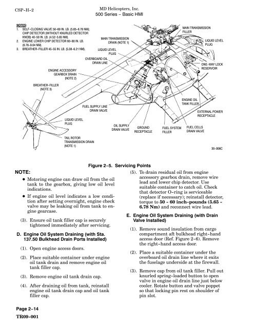
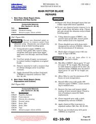
CSP−H−2<strong>MD</strong> <strong>Helicopters</strong>, Inc.500 Series − Basic HMINOTES:1. SELF−CLOSING VALVE 50−60 IN. LB. (5.65−6.78 NM);CHIP DETECTOR (WITHOUT KNURLED DETECTORKNOB) 40−50 IN. LB. (4.52−5.65 NM).2. ENGINE LOWER CHIP DETECTOR 60−80 IN. LB.(6.78−9.04 NM).3. BREATHER−FILLER 45−55 IN. LB. (5.08−6.21 NM).ENGINE ACCESSORYGEARBOX DRAIN(NOTE 2)MAIN TRANSMISSIONDRAIN (NOTE 1)LIQUID LEVELPLUGOVERBOARD OILDRAIN LINEMAIN TRANSMISSIONFILLERLIQUID LEVELPLUGONE−WAY LOCKRESERVOIRBREATHER−FILLER(NOTE 3)LIQUID LEVELPLUGFUEL SUPPLY LINEDRAIN VALVEOIL SUPPLYDRAIN VALVEGROUNDRECEPTACLEFUEL SYSTEMFILLERENGINE OILTANK FILLERFUEL CELLSDRAIN VALVEEXTERNAL POWERRECEPTACLETAIL ROTORTRANSMISSION DRAIN(NOTE 1)30−006CNOTE: Motoring engine can draw oil from the oiltank to the gearbox, giving low oil levelindications. If engine oil level indicates a low conditionafter setting overnight, engine checkvalve may be leaking oil from tank to enginegearcase.(3). Ensure oil tank filler cap is securelytightened immediately after servicing.D. Engine Oil System Draining (with Sta.137.50 Bulkhead Drain Ports Installed)(1). Open engine access doors.(2). Place suitable container under engineoil tank drain and remove engine oiltank filler cap.(3). Remove engine oil tank drain cap.(4). After draining oil from tank, reinstallengine oil tank drain cap and oil tankfiller cap.Figure 2−5. Servicing Points(5). To drain residual oil from engineaccessory gearbox drain, remove wirelead and lower chip detector. Usesuitable container to catch oil. Checkthat detector O−ring is serviceable(replace if necessary); reinstall detector,torque to 50 − 60 inch−pounds (5.65 −6.78 Nm) and reconnect wire lead.E. Engine Oil System Draining (with DrainValve Installed)(1). Remove sound insulation from cargocompartment aft bulkhead right−handaccess door (Ref. Figure 2−6). Removethe right−hand access door.(2). Place a suitable container under theoverboard oil drain line where it exitsthe fuselage underside at the firewall.(3). Remove cap from oil tank filler. Pull outknurled spring−loaded button to openvalve in engine oil drain line just belowcooler. Rotate button and valve poppetso that locking pin rest on shoulder ofpin slot.Page 2−14TR09−001
<strong>MD</strong> <strong>Helicopters</strong>, Inc.500 Series − Basic HMICSP−H−2(4). After draining the oil from the tank,reinstall the filler cap and close oildrain valve; ensure that poppet pin is instop slot.(5). Install access door and sound insulation.(6). To drain approximately 1/2 pint (0.23 L)of residual oil from engine accessorygearbox drain (Ref. Figure 2−5) removethe wire lead and the lower chipdetector. Use a suitable container tocatch the oil. Check that detectorpacking is serviceable (replace ifnecessary), reinstall detector, torque to50 − 60 inch−pounds (5.65 − 6.78Nm), and reconnect wire lead.F. Engine Oil System FlushingThe following procedure is for flushing oil thatas been contaminated or when changing thetype of oil.(1). Drain oil from engine, oil tank and oilcooler (Refer to Engine Oil SystemDraining).(2). Replace engine oil filter(s) (Ref. AllisonOperation and Maintenance Manual)(3). Refill engine oil system (Refer to Filling− Engine Oil System).(4). Operate engine for five minutes, shutdown and repeat steps (1). thru (3).G. Main Rotor and Tail Rotor TransmissionFillingTransmission (gearbox) oil should be replacedwith new oil whenever it is drained from thegearbox.NOTE: Inspection of internal ring gear bolts isrequired after oil is drained from the mainrotor transmission, at intervals specified inCSP−H−4, before refilling with oil.(1). Check transmission oil level in liquidlevel plug.(2). Replenish with correct oil until thelevel reaches FULL on the plug.(a). Fill main transmission by liftingbreather−filler cap and insertingspout of oil can into opening. Checkthat spring−loaded cap closes whenoil can spout is removed.(b). Fill tail rotor transmission by removinglockwire, unscrewing breather−filler and pouring oil into transmission.Check that filler O−ring isserviceable (replace if necessary),reinstall breather−filler and torque to45 − 55 inch−pounds (5.08 − 6.21Nm); secure with lockwire.NOTE: Breather−filler plugs that have thethreaded insert are installed with thebreather hole rearward.H. Main Rotor Transmission Draining(1). If installed, remove circular drain coverplug and padding for main transmissionfrom forward underside of transmissioncover panel. Otherwise remove,in order, sound insulation, gearboxaccess cover, transmission drainassembly and main transmission cover).(2). Position a suitable (min. 4 qt/4 L)container under main transmissiondrains or drain current configurationtransmission using transmission drainhose (41, Table 2−2).NOTE: Two types of chip detector are installedon the main transmission. The current typechip detector have a knurled knob to removeelectrical chip detector probe. Hand−tightenknob when reinstalling.(3). Remove wire leads, lockwire, chipdetector and self−closing valves.NOTE: The self−closing valve need not be removedif special drain hose is used. Inserthose fitting and turn to drain oil.(4). If damaged, replace O−rings used withchip detector and self−closing valves.(5). After oil has drained, install self−closingvalve and chip detectors. Torquechip detector,without the knurled chipdetector probe knob, 40 − 50 inch−pounds (4.52 − 5.65 Nm). Lockwirevalve to gearbox and detector to valve.Reconnect wire leads.(6). If used, reinstall padding and circulardrain cover plug on forward undersidePage 2−15TR09−001
- Page 6: CSP−H−2MD Helicopters, Inc.500
- Page 9 and 10: MD Helicopters, Inc.500 Series −
- Page 11 and 12: MD Helicopters, Inc.500 Series −
- Page 14 and 15: CSP−H−2MD Helicopters, Inc.500
- Page 16 and 17: CSP−H−2MD Helicopters, Inc.500
- Page 18 and 19: CSP−H−2MD Helicopters, Inc.500
- Page 22 and 23: CSP−H−2MD Helicopters, Inc.500
- Page 24 and 25: CSP−H−2MD Helicopters, Inc.500
- Page 26 and 27: CSP−H−2MD Helicopters, Inc.500
- Page 28 and 29: CSP−H−2ItemNo.Material11 Paint
- Page 30 and 31: CSP−H−2ItemMaterialNo.31 Insula
- Page 32 and 33: CSP−H−2MD Helicopters, Inc.500
- Page 35 and 36: MD Helicopters, Inc.500 Series −
- Page 37 and 38: MD Helicopters, Inc.500 Series −
- Page 40 and 41: CSP−H−2MD Helicopters, Inc.500
- Page 42 and 43: CSP−H−2MD Helicopters, Inc.500
- Page 44 and 45: CSP−H−2MD Helicopters, Inc.500
- Page 46 and 47: CSP−H−2MD Helicopters, Inc.500
- Page 48 and 49: CSP−H−2MD Helicopters, Inc.500
- Page 50 and 51: CSP−H−2MD Helicopters, Inc.500
- Page 52 and 53: CSP−H−2MD Helicopters, Inc.500
- Page 54 and 55: CSP−H−2MD Helicopters, Inc.500
- Page 56 and 57: CSP−H−2MD Helicopters, Inc.500
- Page 58 and 59: CSP−H−2MD Helicopters, Inc.500
- Page 60 and 61: CSP−H−2MD Helicopters, Inc.500
- Page 62 and 63: CSP−H−2MD Helicopters, Inc.500
- Page 64 and 65: CSP−H−2MD Helicopters, Inc.500
- Page 66 and 67: CSP−H−2MD Helicopters, Inc.500
- Page 68 and 69: CSP−H−2MD Helicopters, Inc.500
- Page 70 and 71:
CSP−H−2MD Helicopters, Inc.500
- Page 72 and 73:
CSP−H−2MD Helicopters, Inc.500
- Page 74 and 75:
CSP−H−2MD Helicopters, Inc.500
- Page 76 and 77:
CSP−H−2MD Helicopters, Inc.500
- Page 78 and 79:
CSP−H−2MD Helicopters, Inc.500
- Page 80 and 81:
CSP−H−2MD Helicopters, Inc.500
- Page 82 and 83:
CSP−H−2MD Helicopters, Inc.500
- Page 84 and 85:
CSP−H−2MD Helicopters, Inc.500
- Page 86 and 87:
CSP−H−2MD Helicopters, Inc.500
- Page 88 and 89:
CSP−H−2MD Helicopters, Inc.500
- Page 90:
CSP−H−2MD Helicopters, Inc.500