Seko Mag FlowMeter Instructi.. - UK
Seko Mag FlowMeter Instructi.. - UK
Seko Mag FlowMeter Instructi.. - UK
- No tags were found...

You also want an ePaper? Increase the reach of your titles
YUMPU automatically turns print PDFs into web optimized ePapers that Google loves.
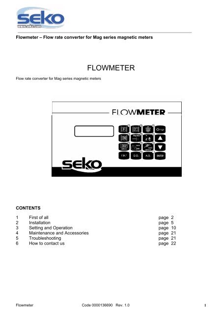
Flowmeter – Flow rate converter for <strong>Mag</strong> series magnetic metersFlow rate converter for <strong>Mag</strong> series magnetic metersFLOWMETERCONTENTS1 First of all page 22 Installation page 53 Setting and Operation page 104 Maintenance and Accessories page 215 Troubleshooting page 216 How to contact us page 22Flowmeter Code 0000136690 Rev. 1.0 1
Flowmeter – Flow rate converter for <strong>Mag</strong> series magnetic meters1 FIRST OF ALL1.1 WELCOME Please read this manual carefully, taking particular note of the warnings provided. Always apply the necessarysafety procedures, including the use of adequate protection for your face, eyes, and clothing.1.2 PACK CONTENTSElectronic converter1.3 TECHNICAL CHARACTERISTICSPower supply 230 Vac 50HzProtection Level IP 65Analogue mA Outputs: 0.4 – 20 mADigital Outputs: N° 4 settableWeight: 2 Kg.Display: two, sixteen-character lines, backlitFlowmeter Code 0000136690 Rev. 1.0 2
Flowmeter – Flow rate converter for <strong>Mag</strong> series magnetic meters1.4 WARNINGS- CHECKS BEFORE METERINGOnce the magnetic meter has been installed and connected up, and the instrumentation connected to it, checkthe following points before beginning with measuring:a) Check that the serial number on the Flowmeter adaptation board corresponds to that on the magneticmeter to which it is connected.b) Make sure that the electrical connections between various devices are sound.c) Make sure that the fixing screws for the electrical connections are tightened properly.d) Check that the cable clamps and hose gaskets are sealed properly.e) Check that the flow direction is as indicated by the arrow on the meter casing.f) Check that the meter is properly earthed, in compliance with UNI standards.- PREPARING FOR METERINGIf all the checks indicated in point 4.1 produce positive results, prepare for metering as follows:- CHECK THE ZERO POINTa) Fill the meter with liquid and make sure it is still.b) Leave the electrical power supply to the converter on for at least 10 minutes.c) Check that the display reads exactly 0.0.- CHECK THE FLOW DIRECTIONa) Allow the liquid to flow.b) Check that the signal shown on the display tends to increase positively. If the signal tends towards anegative value, check that the flow direction is as indicated by the arrow on the meter casing. If this is notthe case, repeat the steps indicated in point 3 – INSTALLATION, so that the direction of flow is as indicatedby the arrow.- MEASUREMENTHaving completed the operations indicated above, start metering. While the fluid is moving a linear 4-20 mAoutput signal can be obtained for the flow rate. Now set up the converter correctly as indicated below.1. – PROGRAMMING AN AP501 – AP501/B CONVERTER, WITHOUT OPTIONAL EXTRA D(see optional extras)This type of converter is programmed in the factory using the data supplied, as it does not have aprogramming keyboard.2. – PROGRAMMING AN AP501 – AP501/B CONVERTER, WITH OPTIONAL EXTRA D(see optional extras)AP501-AP501/B converters come with a 16-key membrane type keyboard. These keyboards can be used tofully configure the instruments to suit the magnetic meter connected to them, the type of output to be obtained,and how information is to be displayed. The symbols shown on the individual keys are mnemonic, makingprogramming user-friendly, without having to remember what functions must be called up.The words shown between square brackets are as they appear on the display, while those between normalbrackets are comments.The converter has an operator’s key, used to block the programming function. This device is used to preventunauthorised personnel changing the settings.AUTOMATION PROGETTI supplies the converter with the KEY = 0. This can be changed by authorisedpersonnel.Flowmeter Code 0000136690 Rev. 1.0 3
Flowmeter – Flow rate converter for <strong>Mag</strong> series magnetic meters1.5 MATERIALS REQUIRED FOR INSTALLATIONGet some plugs and an electric screwdriver.Flowmeter Code 0000136690 Rev. 1.0 4
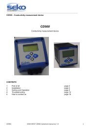
Flowmeter – Flow rate converter for <strong>Mag</strong> series magnetic meters2 INSTALLATION2.1 ANCHORING THE SYSTEMThe figure below on this page shows an example of aninstallation. For outdoor installations we recommend using aroof to protect boxes on North facing walls.2.2 Instrument keyboardStarting from the first key – bottom left.Code DescriptionF.N. Function numberD.O [0] Digital Output (Output Digital)A.O [.] Analog Output (Analog Digital)ENTER EnterDISPLAY [1] Display ModeMAX-MIN [2] Max and Min SettingBATCH [3]ARROW Down arrowDN [4] Change meter section (ND)FILTER [5] Measurement filterL-Kg [6] Unit of measurement displayedARROW Up arrowF[7] FunctionS[8] Value totaliserTIMER[9] TimerKEY Input impedanceFlowmeter Code 0000136690 Rev. 1.0 5
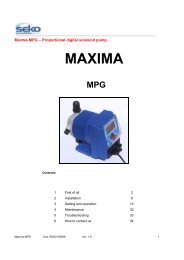
Flowmeter – Flow rate converter for <strong>Mag</strong> series magnetic meters2.3 ELECTRICAL CONNECTIONSCode Description1-2-3-4-5-6 Input for Rs2327 Meter electrode 18 Meter electrode 29 Meter earth10 Meter coil 111 Meter coil 212-13 Digital imput14-15-16-17 Output 4-20 mA18-19 Digital output 1 [50 V 0,2 A relay]20-21 Digital output 2 [50 V 0,2 A relay]22-23 Digital output 3 [50 V 0,2 A relay]24-25 Digital output 4 [50 V 0,2 A relay]26 GND27 Phase (220 Vac)28 Neutral (220 Vac)29 EarthFuse 125 mA 230Vac; 250 mA 115 Vac;CN5 Connector for MAG meter KeyFlowmeter Code 0000136690 Rev. 1.0 6
Flowmeter – Flow rate converter for <strong>Mag</strong> series magnetic metersElectrical connection layout for meterMeter – converter connection table<strong>Mag</strong> connection Wire colour Flowmeter connection Wire colour1 Red 7 Red2 White 8 White3 Black + White + Display 9 Black4 Green 10 Green5 White 11 White<strong>Mag</strong> connectionwithout connectorPassive mA outputMeter with connector – converter connection table<strong>Mag</strong> connection Flowmeter connection Wire colourPre-wired connector 7 Red8 White9 Black10 Green11 WhiteFlowmeter Code 0000136690 Rev. 1.0 7
Flowmeter – Flow rate converter for <strong>Mag</strong> series magnetic metersExample of a passive mA Output:Vdc voltage between 10 and 30 VdcMaximum charge between 50 and 1000 Ohms.Example of an active mA Output:Form a bridge between terminals 14 and 15Maximum charge 600 OhmActive mA output Max 600Example of a connection for resetting or blocking metering:Example of a connection for a digital output:Each output is fitted with a cleancontact relay – technicalcharacteristics, 50 Vac 200 mA.All the outputs can be setusing the menu, such as:• Min/max alarm threshold• Delay totaliser• Presetting device output• Fault signal• Flow directionFlowmeter Code 0000136690 Rev. 1.0 8
Flowmeter – Flow rate converter for <strong>Mag</strong> series magnetic meters2.4 PLUMBINGSee the Manual for the <strong>Mag</strong> Series magnetic Meter (Code 0000136689).Flowmeter Code 0000136690 Rev. 1.0 9
Flowmeter – Flow rate converter for <strong>Mag</strong> series magnetic meters3 SETTING AND OPERATION- KEY INSERTION• Press the OPERATOR KEY key.• Enter the Standard key number, zero (0) [ * ]• Press Enter [ CORRECT ]- LINKING THE CONVERTER TO THE METER’S ND• Enter the key.• Press the ND DIAMETER key• Press the arrow key a number of times, until the required ND is reached[ 3, 6, 8, 10, 15, 20, 25, 32, 40, 50, 65. 80, 100, 125, 150, 175, 200, 250, 300,350, 400, 450, 500, 600, 700, 800, 900, 1000, 1100, 1200, 1400]• Press EnterDNENTER4- PROGRAMMING THE INSTANTANEOUS FLOW RATE TECHNICAL UNIT• Enter the key.l Kg• Press [ UNIT OF MEASUREMENT / FLOW RATE ]• Press the arrow key a number of times, until the technical unit required is reached.6(Only with option 6)[ l/h, l/m, cc/s, %V, kg/h, kg/m, g/s, m/s, for ND 3 to 10[ l/h, l/m, cc/s, %V, kg/h, kg/m, g/s, m/s, for ND 15 to 80[ l/h, l/m, cc/s, %V, kg/h, kg/m, g/s, m/s, for ND 100 to 700[ l/h, l/m, cc/s, %V, kg/h, kg/m, g/s, m/s, for ND 800 to 1400.(Only with option 12)[ l/h, l/m, cc/s, %V, kg/h, kg/m, g/s, m/s, for ND 3 to 8[ l/h, l/m, cc/s, %V, kg/h, kg/m, g/s, m/s, for ND 10 to 80[ l/h, l/m, cc/s, %V, kg/h, kg/m, g/s, m/s, for ND 100 to 500[ l/h, l/m, cc/s, %V, kg/h, kg/m, g/s, m/s, for ND 600 to 1400.• Press EnterENTERFlowmeter Code 0000136690 Rev. 1.0 10
Flowmeter – Flow rate converter for <strong>Mag</strong> series magnetic meters- PROGRAMMING THE TECHNICAL UNITS FOR THE TOTALISERS(Only with options G, H, or Y).l Kg• Enter the key.• Press the UNIT OF MEASUREMENT / IMPULSES icon twice.• Press the arrow key a number of times, until the technical unit required is reached.6(Only with option 6)[ cc, cl, dl, l, dal, g, dg, hg, kg, dkg, for ND 3cl, dl, l, dal, hl, dg, hg, kg, dkg, q, for ND 6 to 10.dl, l, dal, hl, mc, hg, kg, dkg, q, t, for ND 15 to 32l, dal, hl, mc, dmc, kg, dkg, q, t, dt, for ND 40 to 100dal, hl, mc, dmc, hmc, dkg, q, t, dt, ht, for ND 125 to 350hl, mc, dmc, hmc, kmc, q, t, dt, ht, kt, for ND 400 to 1400.(Only with option 12)[ cc, cl, dl, l, dal, g, dg, hg, kg, dkg, for ND 3cl, dl, l, dal, hl, dg, hg, kg, dkg, q, for ND 6 to 8dl, l, dal, hl, mc, hg, kg, dkg, q, t, for ND 10 to 25l, dal, hl, mc, dmc, kg, dkg, q, t, dt, for ND 32 to 80dal, hl, mc, dmc, hmc, dkg, q, t, dt, ht, for ND 100 to 300hl, mc, dmc, hmc, kmc, q, t, dt, ht, kt, for ND 350 to 1000mc, Dmc, hmc, kmc, Dkm, t, Dt, ht, kt, Dkt, per DN 1100 to 1400( cl=0,01 l, dl=0,1 l, dal=10 l, hl=100 l, dg=10 g, hg=100 g, dkg=10 Kg, dmc=10 mc, dt=10 t,hmc=100 mc, ht=100 t, kmc=1000 mc, kt=1000 t , dkt=10000 t )• Press EnterENTERNOTE: When the technical unit is changed, the number of impulses alreadycounted does not change.PROGRAMMING HOW THE FIRST LCD LINE IS DISPLAYED• Enter the key.• Press the LCD line icon [ DISPLAY LINE 1 ]DISPLAY• Press the arrow keys a number of times, until the required message is reached1Por (Instantaneous Flow Rate).Tot+ (Absolute direct flow rate totaliser) (only with options H, or Y).Taz+ (Partial direct flow rate totaliser) (only with options G or Y).Tot- (Absolute inverse flow rate totaliser) (only with option Y).Taz- (Partial inverse flow rate totaliser) (only with option Y).Smin (minimum settin) (only with option R).Smax (maximum setting) (only with option R).Pred (presetting device count) (only with option Y).Core (Timer) (only with option U).Time (only with option U).Date (only with option U).CYCLE (Display at 5 second intervals, for the following messages): Por, Tot+, Tot-, Smin,Smax, Pred, Core) ]Flowmeter Code 0000136690 Rev. 1.0 11
Flowmeter – Flow rate converter for <strong>Mag</strong> series magnetic meters• Press EnterENTERNOTES:When (optional) displays are selected that have not been activated, the second line reads“OPTIONAL”.PROGRAMMING HOW THE SECOND LCD LINE IS DISPLAYED• Enter the key.• Press the LCD line icon twice [ DISPLAY LINE 2 ]• Programme using the same procedure used for the first line.DISPLAY1PROGRAMMING DIGITAL OUTPUT 1(Only with option R).• Enter the key.D.O.• Press [DIGIT. OUTPUT # 1]• Press the up arrow a number of times, until the required message is reached.Impulsi Dir. (Direct Flow Rate)Impulsi Inv. (Inverse Flow Rate) (only with option Y).Presetting device (end count impulse) (only with option Y).Low liquid level (hose empty alarm) (only with option W).Min Flow Rate Alarm (Minimum flow rate alarm)Max Flow Rate Alarm (Maximum flow rate alarm)Flow direction (only with option P), Data fault• Press EnterENTER0PROGRAMMING OF DIGITAL OUTPUTS 2, 3, 4(Only with option R).• Enter the key.• Push the digital output icon, twice, three times, four times [DIGIT.OUTPUT # 2, 3, 4]• Proceed as for programming digital output 1D.O.0PROGRAMMING THE DURATION OF TOTALISER IMPULSES FOR DIGITAL OUTPUT 1(Only with option R).• Enter the key.• Press the digital output icon [ 5 (at the end of the second row of the LED)].(5 is the impulse duration in milliseconds).• Press the down arrow a number of times, until the required impulse duration isreached.• [5, 10, 15, 20, 25, 35, 50, 75, 100, 150, 200, 250, 350, 500, 750, 999 ( 1 sec )].• Press EnterNOTES:This programming cannot be done on the alarm outputs and the end count, because theywill continue to be active for the entire duration of the alarm or until the presetting device isreset.The duration of the impulse must be compatible with the type of totaliser connected up andthe totalling system chosen beforehand.With option M the duration is 20 msec.D.O.0ENTERFlowmeter Code 0000136690 Rev. 1.0 12
Flowmeter – Flow rate converter for <strong>Mag</strong> series magnetic metersPROGRAMMING OF THE DURATION OF TOTALLING IMPULSES FOR DIGITAL OUTPUTS 2,3, 4(Only with option R).• Enter the key.• Push the digital output icon, twice, three times, or four times [5]D.O.0• Proceed as for programming the duration of totaliser impulses for digital output 1.PROGRAMMING THE TYPE OF ANALOGUE OUTPUT(Only with option P).• Enter the key.• Press the Analogue Output icon [Flow Rate]• Press the Analogue Output icon a number of times, until the type of outputrequired is reached.Direct Flow Rate ( 0 - +100% → 4 - 20mA ),Inverse Flow Rate ( 0 - +100% ( 4 - 20mA ),Two-way Flow Rate (-100 – 0 - +100% 4-12-20 mA).Module Flow Rate (0 - +100% 4-20 mA; 0 - -100% 4-20 mA).• Press EnterA.O.ENTER.PROGRAMMING THE SCALE RANGE FOR THE ANALOGUE OUTPUT• Enter the key.• Press the Analogue Output icon [FS (Scale Range)]• Hold the arrows down until the required scale range is reached.• Press EnterA.O.ENTER.NOTES:If the display is not shown in percentage terms, each individual time the key is pressed doesnot relate to a change in the scale range shown). We therefore recommend blocking thedisplay at the time of going from the lower value to the required value.PROGRAMMING THE FILTER TIME• Enter the key.• Press the Filtration time icon [FILTRATION]• Press the arrow key a number of times, until the required filtration time is reached [1, 2, 4, 8 ] (The converter gives the average of the readings taken in 1, 2, 4, or 8seconds).• Press EnterENTERPROGRAMMING THE MINIMUM SETTING(Only with option R).• Enter the key.• Press the Minimum Setting icon [MINIMUM FLOW RATE SET. / Smin]• Hold the arrows down until the required setting is reached.• Press EnterMAXMIN2ENTERFlowmeter Code 0000136690 Rev. 1.0 13
Flowmeter – Flow rate converter for <strong>Mag</strong> series magnetic metersPROGRAMMING MAXIMUM SETTINGS(Only with option R).• Enter the key.• Press the Maximum Setting icon [MAXIMUM FLOW RATE SET./ Smax]• Proceed as for programming the minimum setting.MAXMIN2PROGRAMMING THE PRESETTING DEVICE(Only with option Y).• Press the presetting device icon [PRESETTING]• Hold the arrows down until the required value is reached.[ 0 ÷ 30000 ]• Press EnterBATCHENTER3PROGRAMMING THE TYPE OF RESETTING FOR THE PRESETTING DEVICE(Only with option Y).• Push the presetting device icon twice [RESET TYPE]• Press the arrows to choose manual [MAN] or automatic [AUT] resetting.BATCHENTER3When in manual mode the presetting device can be reset using the “key” key.When in automatic mode, the device resets itself automatically when the end count hasbeen reached.• Press EnterENTERMANUAL RESETTING OF THE PRESETTING DEVICE(Only with option Y).• Push the presetting device icon twice [RESET WITH KEY]• Press the “Key” key.• Press EnterBATCHENTER3PROGRAMMING THE OPERATOR’S KEY• Enter the current key.• Press the xxxx and display icons.• Press Enter [OPERATOR’S KEY]• Enter the new numerical code. This field must bebetween 0 and 99·999·999.• Press EnterPROGRAMMING THE SPECIFIC WEIGHT• Enter the key.• Press Minimum and Maximum Setting xxxx• Press Enter [SPECIFIC WEIGHT]• Enter the specific weight value.This field must be between 0.0000 and 1.9999.F.N.F.N.DISPLAY1ENTERENTERMAXMIN2ENTERENTERFlowmeter Code 0000136690 Rev. 1.0 14
Flowmeter – Flow rate converter for <strong>Mag</strong> series magnetic metersAll values must be entered with four decimal places.• Press Enter- PROGRAMMING THE TIME(Only with option U).• Enter the key.• Press xxxx and presetting device• Press Enter [TIME]• Enter the 6 digits for the time.• Press Enter to start the clock.• Press EnterPROGRAMMING THE DATE(Only with option U).• Enter the key.• Press xxxx ND Diameter• Press Enter [DATE]• Enter the 6 digits for the date.• Press Enter twice.PROGRAMMING THE CUT-OFF(Only with option K).• Enter the key.• Press xxxx and Function.• Press Enter [CUT-OFF THRESHOLD]• Hold the arrows down until the required value is reached.(Range = 1,5 – 20% for converters withoption 6 and 0,75-20% for converters with option 12).• Press EnterENTERPROGRAMMING THE SERIAL ADDRESS(Only with option 4 or 3).• Enter the key.• Press xxxx, display and digital output• Press Enter [SERIAL ADD. =]• Press the arrow keys a number of times, until the requiredvalue is reached.This field must be between 1 and 255.• Press Enter- PROGRAMMING THE SERIAL BAUD-RATE(Only with option 4 or 3).• Enter the key.• Press xxxx and display.• Press Enter [SER. BAUD-RATE =]• Press the arrow keys a number of times, until the requiredvalue is reached[ 300 , 600 , 1200 , 2400 , 4800 , 9600 , 19200 , 38400 ]• Press EnterFlowmeter Code 0000136690 Rev. 1.0 15
Flowmeter – Flow rate converter for <strong>Mag</strong> series magnetic meters- SETTING THE ZERO• Enter the key.• Press xxxx, display, and batch.Press Enter [ZERO MEASURE./CONFIRM WITH KEY]• Press “Key” [WAIT]The converter uses the programmed display mode again afterabout 15 seconds have elapsed.F.N.DISPLAY1BATCHENTER3NOTES:Only use this function when you are sure that the meter is at full capacity, with the liquid still.If this is not done, there will be a zero error.Normally, it is not necessary to use this function because Automation Progetti sees to thissetting in the factory. However, this function perfectly aligns the converter with the meterconnected to it.- PROGRAMMING THE COMMUNICATION LANGUAGE• Enter the key.• Press xxxx, display and function.• Press Enter [LANGUAGE SELECTION / ENGLISH].• Press the arrows to select the language to be used.• Press EnterF.N.DISPLAY1FENTER7- CONFIGURATION OF THE DIGITAL INPUT(Only with option T).ENTER• Enter the key.• Press xxxx, Min & Max Setting, and Digital Output• Press Enter [CONF.DIG.INPUT ]• Press the arrow keys a number of times, until the required message isreached. Block MeasurementRes. Tot. Parz. (Reset Partial Totalisers)(Only with option G or Y).Preset Presett. (Preset Presetting Device) (only with option Y).• Press EnterNOTES:When (optional) displays are selected that have not been activated, the second line reads“OPTIONAL”.F.N.MAXMIN2D.O.ENTERENTER0- DISPLAYING THE INSTANTANEOUS FLOW RATE• Press function [CURRENT FLOW RATE / Por]• Press EnterF7ENTERNOTES:The sequence for the totalisers indicated below varies, depending on the option activated.This means that totalisers that have not been enabled will be displayed, while thoseenabled will be displayed in sequence.Flowmeter Code 0000136690 Rev. 1.0 16
Flowmeter – Flow rate converter for <strong>Mag</strong> series magnetic meters- DISPLAYING THE ABSOLUTE DIRECT FLOW TOTALISER(Only with option H, or Y).• Press Absolute Totaliser [ABSOLUTE TOTALISER / Tot+]• Press Enter- DISPLAYING THE ABSOLUTE INVERSE FLOW TOTALISER(Only with option Y).• Press Absolute Totaliser twice [ABSOLUTE TOTALISER / Tot-]• Press Enter- DISPLAYING THE ABSOLUTE DIRECT PARTIAL FLOW TOTALISER(Only with option G or Y).• Press Absolute Totaliser three times [ZEROABLE TOTALISER / Taz+]• Press Enter- DISPLAYING THE ABSOLUTE INVERSE PARTIAL FLOW TOTALISER(Only with option Y).• Press Absolute Totaliser four times [ZEROABLE TOTALISER / Taz-]• Press Enter8ENTER8ENTER8ENTER8ENTERFlowmeter Code 0000136690 Rev. 1.0 17
Flowmeter – Flow rate converter for <strong>Mag</strong> series magnetic meters- RESETTING PARTIAL TOTALISERS(Only with option G or Y).• Enter the key.• Press Absolute Totaliser five times[RESET TOTALISER / CONFIRM WITH KEY]• Press the “Key” key [RESET TOTALISER / Taz+]• Press Enter- DISPLAYING THE TIMER(Only with option U).• Press the TIMER icon.• Press Enter- DISPLAYING THE PROGRAMMED ND• Press the ND DIAMETER icon.• Press Enter- DISPLAYING THE FILTRATION TIME• Press the FILTRATION icon.• Press Enter8ENTERENTER00:009ENTERDN4ENTERFILTER5ENTER- DISPLAYING THE INSTANTANEOUS FLOW RATE TECHNICAL UNIT• Press the UNIT OF MEASUREMENT / FLOW RATE icon• Press EnterlKg6ENTERFlowmeter Code 0000136690 Rev. 1.0 18
Flowmeter – Flow rate converter for <strong>Mag</strong> series magnetic meters- DISPLAYING THE TECHNICAL UNITS FOR THE TOTALISERS(Only with option G, H, or Y).• Press the UNIT OF MEASUREMENT / IMPULSES icon twice.• Press Enter- DISPLAYING THE MESSAGE ON THE FIRST LINE OF THE LCD• Press Display [DISPLAY LINE 1]• Press Enter- DISPLAYING THE MESSAGE ON THE SECOND LINE OF THE LCD• Press Display [DISPLAY LINE 2] twice• Press Enter- DISPLAYING THE MINIMUM SETTING(Only with option R).• Press Min and Max Setting [MINIMUM FLOW RATE SET. / Smin]• Press Enter- DISPLAYING THE MAXIMUM SETTING(Only with option R).• Press Min and Max Setting twice [MAX FLOW RATE SET. / Smax]• Press Enter- DISPLAYING THE PRESETTING DEVICE(Only with option Y).• Press the batch icon [PRESETTING]• Press EnterlKg6ENTERDISPLAYENTERDISPLAYENTERMAXMIN112ENTERMAXMIN2ENTERBATCH3- DISPLAYING THE RESETTING MODE(Only with option Y).• Push the batch icon twice [RESET WITH KEY / RESET MODE]• Press Enter- DISPLAYING DIGITAL OUTPUT 1 AND THE RELATED DURATION OF THE TOTALISERIMPULSES(Only with option R).D.O.• Press Digital Output [DIGIT. OUTPUT # 1].0• Press Enter- DISPLAYING DIGITAL OUTPUTS 2, 3, 4 AND THE RELATED DURATION OF TOTALISERIMPULSES(Only with option R).• Push the digital output icon, twice, three times, or four times[DIGIT. OUTPUT # 2 , 3 , 4 ]D.O.0• Press Enter ENTERENTERBATCHENTERENTER3ENTERFlowmeter Code 0000136690 Rev. 1.0 19
Flowmeter – Flow rate converter for <strong>Mag</strong> series magnetic meters- DISPLAYING THE ANALOGUE OUTPUT• Press the Analogue Output icon [Flow Rate]• Press EnterA.O.ENTER.- CONFIRMING CONFIGURATION FOLLOWING AN “EEPROM DATA / MEMORY ERROR”MESSAGE• Check the parameters programmed.F.N.• Enter the key.l Kg6• Press xxxx and unit of measurement[CALC. CHECKS / CONFIRM WITH KEY]• Press the “Key” key.ENTER• Press Enter- DISPLAYING THE PROGRAM VERSION• Enter the key.• Press xxxx, display and unit of measurement• Press Enter [AP501 V1.0.XXX / XXX XXX XXX XXX](The number 1.0 after the letter v indicates the versionof the program installed in the converter and the versionof the <strong>Instructi</strong>on Manual).• Press EnterF.N.DISPLAY1lKg6ENTERENTER- DISPLAYING THE SERIAL NUMBER• Enter the key.• Press the xxxx, display, and totaliser• Press Enter [SERIAL NUMBER]• Press EnterF.N.DISPLAY18ENTERENTERFlowmeter Code 0000136690 Rev. 1.0 20
Flowmeter – Flow rate converter for <strong>Mag</strong> series magnetic meters4 MAINTENANCE AND ACCESSORIES4.1 AccessoriesCONSULT YOUR LOCAL DEALER4.2 MaintenanceShould an incorrect measurement arise, check the integrity of the wiring and clean the meter, being careful not todamage the measuring electrodes.5 TROUBLESHOOTING- ERROR MESSAGES• EEPROM DATA / MEMORY ERROR (See F. N° 6)• ** WARNING ** / CHECK-SUM WRONG• EQUIPMENT / CANNOT BE USED• USER DATA / PARAMETER ERROR• CHECK: ND, / FILTER, L-KG,D.O.• INITIAL DATA / CONFIG. ERROR• ADC CONVERTER / NOT RELIABLE- SERVICE MESSAGES• AUTOMATION / PROGETTI (manufacturer’s name)• AP501 v1.0 (type and version of software)• SELF-DIAGNOSIS (initial check)• WARNING / AP550 MISSING (highlights the fact that the AP550 board is missing).• WARNING / WIRING INCORRECT (highlights the fact that there is a fault on theconnection between the meter and the converter).• WARNING / NO LIQUID (highlights the fact that the flow rate meter is empty). (Onlywith option W).• OPERATOR NOT / ENABLED (highlights the need for the access key)Flowmeter Code 0000136690 Rev. 1.0 21
Flowmeter – Flow rate converter for <strong>Mag</strong> series magnetic metersWebsite: www.seko.comSEKO ItaliaSEKO Asia pacificSEKO BrasilSEKO DeutschlandSEKO FranceSEKO IbericaSEKO Southern AfricaSEKO <strong>UK</strong>SEKO USAFlowmeter Code 0000136690 Rev. 1.0 22