Seko pHRX Controller_PR 75 C.. - UK
Seko pHRX Controller_PR 75 C.. - UK
Seko pHRX Controller_PR 75 C.. - UK

Create successful ePaper yourself
Turn your PDF publications into a flip-book with our unique Google optimized e-Paper software.
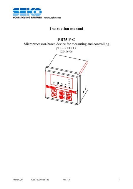
Instruction manual<strong>PR</strong><strong>75</strong> P-CMicroprocessor-based device for measuring and controllingpH – REDOXDIN 96*96<strong>PR</strong><strong>75</strong>C_P Cod. 0000136182 rev. 1.1 1
NOTES FOR THE INSTALLERWARNING: DISCONNECT THE POWER SUPPLY BEFORE INSTALLING THE <strong>PR</strong><strong>75</strong> OR CARRYING OUTANY MAINTENANCE WORK ON IT.This instrument should be installed in a panel to which the power cables and connections to the metering pumps andalarm devices must be led. The cables must end in cable terminals having a cross-section of less than 4 mm 2 and leftlonger than the minimum length required for handy connection to the terminal board.A) Maximum depth inside the switchboardB) Drilling templateC) Lateral layout inside the panel<strong>PR</strong><strong>75</strong>C_P Cod. 0000136182 rev. 1.1 4
CONTROL PANELDISPLAYIconDescriptionS1 Set point 1S2 Set point 2Cal HoldCalibration modeAlarmAlarm7pHCalibration with a pH 7 solution4/9 pH Calibration with a pH 4 or 9,22 solutionSecNot availableMinNot availablepHpH measurement modemVRedox potential measurement mode°C Temperature% Quality of the electrodemAMA outputKEYPADKeyFunctionS1 View Set point 1S2 View Set point 2CAL HOLDCalibration procedure<strong>PR</strong>G STEPProgramming procedure°C Modification of displayed parametersModification of displayed parameters<strong>PR</strong><strong>75</strong>C_P Cod. 0000136182 rev. 1.1 6
MICRO-SWITCHESONOFF1 Type of measurement PH Redox2 Set Point 1 LO HI3 Set Point 2 LO (if used as a set point)NO (if used as an alarm)HI (if used as a set point)NC (if used as an alarm)4 Current output Measurement Adjustment5 Calibration Calibration enabled Calibration disabled6 Programming Programming enabled Programming disabledNOTE . On leaving the factory all the switches are positioned on ON, as shown in the figure.<strong>PR</strong><strong>75</strong>C_P Cod. 0000136182 rev. 1.1 7
MEASURING THE pHWith the <strong>PR</strong><strong>75</strong> P it is possible set the following values in sequence:• set-point 1• set-point 2• use of the 4/20 mA current output• proportional band• number of decimal places to which the pH value has to be expressed.The succession of the operations for setting the values of the parameters that one wants to alter is illustrated in detailbelow.The values that are shown on the display in the following diagrams refer to the default values.Each time the <strong>PR</strong>G key is pressed, the next parameter is accessed. In order to understand which parameter is beingaltered, refer to the icons that light up on the display.A general summary table is provided on page 25.For a better understanding of the programming of the <strong>PR</strong> <strong>75</strong> P instrument, refer to the figures described aboveconcerning the Control panel, Connections and Micro-Switches and the relevant notes.NOTE: To carry out pH measurements, micro-switch n° 1 must be in the ON position.<strong>PR</strong><strong>75</strong>C_P Cod. 0000136182 rev. 1.1 9
2-a) SETTING SET POINT 2as a Set pointALr<strong>PR</strong>G<strong>PR</strong>OGafter 3 sec.<strong>PR</strong>G7.20 LO<strong>PR</strong>G1. Press the <strong>PR</strong>G key and hold it down for 3 seconds.First the wording <strong>PR</strong>OG will appear on the display, after which the value of Set Point 1 will be displayedautomatically.pH icon steady on and S1 icon flashing.2. Press the <strong>PR</strong>G twice. The indication SEt (or ALr) will appear on the display and the S2 icon will flash.3. Press the or keys to select the operating mode of Set Point S2.S2 can function as a set point exactly like S1 (the display will indicate SEt), or as an alarm associated with S1 (thedisplay will indicate ALr).SEt0-14<strong>PR</strong>G<strong>PR</strong>GSEt 8.00 LO<strong>PR</strong>G4. After viewing SEt, press the <strong>PR</strong>G key.The value of Set Point 2 will appear on the display. pH icon steady on and S2 icon flashing.5. Press the or keys to increase or decrease the value of Set Point 2.6. Press the <strong>PR</strong>G key. The indication LO will appear on the display and the S2 icon will flash.The LO value of Set Point S2 cannot be changed using the keypad, but only by positioning micro-switch n°3.NOTE: LO means that once the value of S2 has been set, relay 2 associated with this set point (terminals 15 and16) will only be activated after the pH value of the process that is being controlled falls lower than S2.If micro-switch n° 3 is moved to the OFF position before starting programming, instead of LO theindication HI will appear on the display.HI means that once the value of S2 has been set, the relay associated with this set point (terminals 15 and16) will only be activated after the pH value of the process that is being controlled rises higher than S2.Thus, if we connect a pump to relay 2, and S2 is selected as LO, the pump is set to meter out an alkalinesubstance (it will start to run when the actual value drops below the setpoint value set point); if, on theother hand, S2 is selected as HI , the pump is set to meter out an acid substance (it will start to run whenthe value rises above that of the set point).NOTE: Set Point 2 can also be altered without entering the programming mode.1. Press the S2 key and hold it down.2. Press the or keys to increase or decrease the value of Set Point 2.<strong>PR</strong><strong>75</strong>C_P Cod. 0000136182 rev. 1.1 11
3) SETTING USE OF THE 4/20 OUTPUT<strong>PR</strong>Gafter 3 sec.<strong>PR</strong>G<strong>PR</strong>OG 7.20 LO SEt<strong>PR</strong>GMIS<strong>PR</strong>G<strong>PR</strong>GLO 8.00<strong>PR</strong>G1. Press the <strong>PR</strong>G key and hold it down for 3 seconds.First the wording <strong>PR</strong>OG will appear on the display, after which the value of Set Point 1 will be displayedautomatically.Icon pH icon steady on and S1 icon flashing.2. Press the <strong>PR</strong>G key 5 times. The indication MIS will appear on the display and the mA icon will flash.The value of MIS refers to current output that the <strong>PR</strong> <strong>75</strong> can provide (terminals 3 e 4); this mode cannot bechanged using the keypad, but only by positioning Micro-switch n° 4.NOTE: MIS means that the 4 to 20 mA current output can be used to repeat the measurement throughout thewhole scale (pH 0 to 14).If micro-switch n° 4 is moved to the OFF position before starting programming, instead of MIS theindication REG will appear on the display.REG means that the 4 to 20 mA current output can be used for the purpose of proportional adjustment(referred to set point 1 and to the proportional band) of a pump that can be connected to the power supplyof relay 1.<strong>PR</strong><strong>75</strong>C_P Cod. 0000136182 rev. 1.1 13
4) <strong>PR</strong>OPORTIONAL BAND<strong>PR</strong>Gafter 3 sec.<strong>PR</strong>G<strong>PR</strong>OG 7.20 LO SEt<strong>PR</strong>GMIS<strong>PR</strong>G<strong>PR</strong>GLO 8.00<strong>PR</strong>G<strong>PR</strong>Gb 1.000.5-2.8The proportional band is the interval starting from the SET POINT (the extent of which depends on the value we set)within which the instrument provides a proportional current at the outlet of between 4 and 20 mA.1. Position the micro-switch 4 in the OFF position2. Press the <strong>PR</strong>G key and hold it down for 3 seconds.First the wording <strong>PR</strong>OG will appear on the display, after which the value of Set Point 1 will be displayedautomatically.Icon pH icon steady on and S1 icon flashing.2. Press the <strong>PR</strong>G key 6 times. The indication b 1.00 will appear on the display. It refers to the proportional bandassociated with set point 1. S1 icon flashing and pH icon illuminated.If micro-switch 4 is in the ON position, that is to say if the current output is being used to record the measurement,the proportional band does not serve any purpose.3. Press the or keys to increase or decrease the value of the proportional band.<strong>PR</strong><strong>75</strong>C_P Cod. 0000136182 rev. 1.1 14
5) RESOLUTION OF READING<strong>PR</strong>Gafter 3 sec.<strong>PR</strong>G<strong>PR</strong>OG 7.25 LO SEt<strong>PR</strong>Gb 1.00<strong>PR</strong>GMIS<strong>PR</strong>G<strong>PR</strong>GLO 8.00<strong>PR</strong>G<strong>PR</strong>Gr 0.100.10 / 1.011. Press the <strong>PR</strong>G key and hold it down for 3 seconds.First the wording <strong>PR</strong>OG will appear on the display, after which the value of Set Point 1 will be displayedautomatically.Icon pH icon steady on and S1 icon flashing.2. Press the <strong>PR</strong>G key 7 times. Indication r 0.10 will appear on the display. This refers to the resolution of reading.Icon pH illuminated.3. Press the or keys to choose the resolution you prefer (to the first or second decimal place).4. If you press the <strong>PR</strong>G key again you will exit from programming.The display will indicate the pH value ready by the probe. Icon pH illuminated.If the S1 icon is illuminated this means that, on the basis of the pH value displayed, relay 1 has been activated.If S2 is illuminated this means that relay 2 has been activated: if S2 has been chosen as an alarm and “normally closed”(nC) has been selected as the alarm status, this means that the value is within the range in respect of set point 1. If“normally open” (nO) has been selected as the alarm status, this means that the value is beyond this range (there is analarm status). In this case the Alarm icon and the backlighting of the display will also flash.<strong>PR</strong><strong>75</strong>C_P Cod. 0000136182 rev. 1.1 15
MEASURING THE REDOX POTENTIALWith the <strong>PR</strong><strong>75</strong> P it is possible set the following values in sequence:• set-point 1• set-point 2• use of the 4/20 mA current output• proportional bandThe succession of the operations required in order to set the values of the parameters that you may wish to change isillustrated here below.The values that are shown on the display in the following diagrams refer to the default values.Each time the <strong>PR</strong>G key is pressed, the next parameter is accessed. In order to understand which parameter is beingaltered, refer to the icons that light up on the display.A general summary table is provided on page 26.For a better understanding of the programming of the <strong>PR</strong> <strong>75</strong> P instrument, refer to the figures described aboveconcerning the Control panel, Connections and Micro-Switches and the relevant notes.NOTE: To measure the Redox potential, micro-switch n° 1 must be in the OFF position.<strong>PR</strong><strong>75</strong>C_P Cod. 0000136182 rev. 1.1 16
1) SETTING SET POINT 1-999 / 999<strong>PR</strong>Gafter 3 sec.<strong>PR</strong>G<strong>PR</strong>OG 500 LO1. Press the <strong>PR</strong>G key and hold it down for 3 seconds.First the wording <strong>PR</strong>OG will appear on the display, after which the value of Set Point 1 will be displayedautomatically.Icon mV icon steady on and S1 icon flashing.2. Press the or keys to increase or decrease the value of Set Point 1.3. Press the <strong>PR</strong>G key. The indication LO will appear on the display and the S1 icon will flash.The LO of Set Point S1 cannot be changed using the keypad, but only by positioning Micro-switch n° 2.NOTE: LO means that once the value of S1 has been set, relay 1 associated with this set point (terminals 13 and14) will only be activated when the value of the Redox potential of the process that is being controlleddrops lower than S1.If micro-switch n° 2 is moved to the OFF position before starting programming, instead of LO theindication HI. will appear on the display.HI means that once the value of S1 has been set, the relay associated with this set point (terminals 13 and14) will be activated only when the value of Redox potential of the process that is being controlled riseshigher than S1.Thus, if we connect a pump to relay 1, and S1 is selected as LO the pump it will start to run whenthe actual value drops below the setpoint value; if, on the other hand, S1 is selected as HI, the pumpwill start to run when the value rises above that of the set point.NOTE: Set Point 1 can also be altered without entering the programming mode.1. Press the S1 key and hold it down.2. Press the or keys to increase or decrease the value of Set Point 1.<strong>PR</strong><strong>75</strong>C_P Cod. 0000136182 rev. 1.1 17
2-a) SETTING SET POINT 2as a Set pointALr<strong>PR</strong>G<strong>PR</strong>OGAfter 3 sec.<strong>PR</strong>G500 LO<strong>PR</strong>GSEt1. Press the <strong>PR</strong>G key and hold it down for 3 seconds.First the wording <strong>PR</strong>OG will appear on the display, after which the value of Set Point 1 will be displayedautomatically.Icon mV icon steady on and S1 icon flashing.2. Press the <strong>PR</strong>G twice. The indication SEt (or ALr) will appear on the display and the S2 icon will flash.3. Press the or keys to select the operating mode of Set Point S2.S2 can function as a set point exactly like S1 (the display will indicate SEt), or as an alarm associated with S1 (thedisplay will indicate ALr).-999 / 999<strong>PR</strong>G<strong>PR</strong>GSEt 720 LO<strong>PR</strong>G4. After viewing SEt, press the <strong>PR</strong>G key.The value of Set Point 2 will appear on the display. Icon mV icon steady on and S2 icon will flash.5. Press the or keys to increase or decrease the value of Set Point 2.6. Press the <strong>PR</strong>G key. The indication LO will appear on the display and the S2 icon will flash.The LO value of Set Point S2 cannot be changed using the keypad, but only by positioning Micro-switch n° 3.NOTE: LO means that once the value of S2 has been set , relay 2 associated with this set point (terminals 13 and14) will only be activated when the value of the Redox potential of the process that is being controlledfalls lower than S2.If micro-switch n° 2 is moved to the OFF position before starting programming, the indication LO willappear on the display instead of HI.HI means that once the value of S2 has been set, the relay associated with this set point (terminals 13 and14) will only be activated when the value of the Redox potential of the process that is being controlledrises higher than S2.Thus, if we connect a pump to relay 2, and S2 is selected as LO, the pump will start to run when theactual value drops below the setpoint value; if, on the other hand, S2 is selected as HI, the pump willstart to run when the value rises above that of the set point.NOTE: Set Point 2 can also be altered without entering the programming mode.1. Press the S2 key and hold it down.2. Press the or keys to increase or decrease the value of Set Point 2.<strong>PR</strong><strong>75</strong>C_P Cod. 0000136182 rev. 1.1 18
2-b) SETTING SET POINT 2as an AlarmALr<strong>PR</strong>G<strong>PR</strong>OGafter 3 sec.<strong>PR</strong>G500 LO<strong>PR</strong>G1. Press the <strong>PR</strong>G key and hold it down for 3 seconds.First the wording <strong>PR</strong>OG will appear on the display, after which the value of Set Point 1 will be displayedautomatically.Icon mV icon steady on and S1 icon flashing.2. Press the <strong>PR</strong>G key twice. The indication SEt (or ALr) will appear on the display and the S2 icon will flash.3. Press the or keys to select the operating mode of Set Point S2.S2 can function as a set point exactly like S1 (the display will indicate SEt), or as an alarm associated with S1 (thedisplay will indicate ALr).50 / 999SEt<strong>PR</strong>G<strong>PR</strong>GALr 720 nO<strong>PR</strong>G4. Once the indication ALr, has appeared on the display, press the <strong>PR</strong>G key.The value of the amplitude of the range of alarm S2 in respect of S1 will be shown on the display. mV icon steadyon and S2 icon flashing.E.G. If S1 = 500 and S2 = 200, the alarm will be triggered off whenever the Redox value is lower than 300(500-200) or is higher than 700 (500+200).When the alarm is triggered the Alarm icon and the backlighting will start to flash.5. Press the or keys to increase or decrease the value of S2.6. Press the <strong>PR</strong>G key. The indication nO will appear on the display and the S2 icon will flash.The nO value cannot be changed using the keypad, but only by positioning Micro-switch n° 3.NOTE: nO (normally open) means that relay 2 associated with S2 (terminals 15 and 16) will only be activatedwhen the value of Redox goes beyond the range of alarm S2 in respect of set point S1.If micro-switch n° 3 is moved to the OFF position before starting programming, instead of nO theindication nC will appear on the display.nC (normally closed) means that relay 2 associated with S2 (terminals 15 and 16) will only be deactivatedwhen the Redox value goes beyond the range of alarm S2 in respect of set point S1.Thus, if we connect a signalling lamp, for example, to relay 2, and S2 is selected as nO, the lamp will light upwhen the Redox value moves beyond the range that has been set; if, on the other hand, S2 is selected as nC, thelight will shut off when the Redox value moves beyond the range that has been set.<strong>PR</strong><strong>75</strong>C_P Cod. 0000136182 rev. 1.1 19
3) SETTING USE OF THE CURRENT OUTPUT<strong>PR</strong>Gafter 3 sec.<strong>PR</strong>G<strong>PR</strong>OG 500 LO SEt<strong>PR</strong>GMIS<strong>PR</strong>G<strong>PR</strong>GLO 720<strong>PR</strong>G1. Press the <strong>PR</strong>G key and hold it down for 3 seconds.First the wording <strong>PR</strong>OG will appear on the display, after which the value of Set Point 1 will be displayedautomatically.Icon mV icon steady on and S1 icon flashing.2. Press the <strong>PR</strong>G key 5 times. The indication MIS will appear on the display and the mA icon will flash.The MIS value refers to the current output that the <strong>PR</strong> <strong>75</strong> can provide (terminals 3 to 4); this mode cannot bechanged using the keypad, but only by positioning Micro-switch n° 4.NOTE: MIS means that the 4 to 20 mA current output can be used to repeat the measurement throughout thewhole scale (-999 to 999 mV).If micro-switch n° 4 is moved to the OFF position before starting programming, instead of MIS theindication REG will appear on the screen.REG means that the 4 to 20 mA current output can be used for the purpose of proportional adjustment(referred to set point 1 and to the proportional band) of a pump that may be connected to the powersupply to relay 1.<strong>PR</strong><strong>75</strong>C_P Cod. 0000136182 rev. 1.1 20
4) <strong>PR</strong>OPORTIONAL BAND<strong>PR</strong>Gafter 3 sec.<strong>PR</strong>G<strong>PR</strong>OG 500 LO SEt<strong>PR</strong>GMIS<strong>PR</strong>G<strong>PR</strong>GLO 720<strong>PR</strong>G<strong>PR</strong>Gb 100The proportional band is the interval starting from the SET POINT (the extent of which depends on the value we set)within which the instrument provides a proportional current at the outlet of between 4 and 20 mA.1. .Position the micro-switch 4 in the OFF position2. Press the <strong>PR</strong>G key and hold it down for 3 seconds.First the wording <strong>PR</strong>OG will appear on the display, after which the value of Set Point 1 will be displayedautomatically.Icon mV icon steady on and S1 icon flashing.3. Press the <strong>PR</strong>G 6 times. The indication b 1.00 will appear on the display. This refers to the proportional bandassociated with set point 1 (micro-switch 4 in the OFF position). S1 icon is flashing and icon mV is on.If micro-switch 4 is in the ON position, that is to say that the current output is being used to record themeasurement, the proportional band will not serve any purpose.1. Press the or keys to increase or decrease the value of the Proportional band.2. If you press the <strong>PR</strong>G key again you will exit from programming.The display will indicate the value of Redox potential read by the probe. Icon mV is on .If the S1 icon is on this means that, based on the Redox value that is displayed, relay 1 has been activated.If S2 is on this means that relay 2 has been activated: if you have chosen S2 as an alarm and “normally closed” (nC)has been selected as the alarm status, this means that the measured value is within the range selected for set point 1. If,on the other hand, “normally open” has been selected as the alarm status (nO), this means that the value measured isbeyond that range (there is an alarm status); in this case the Alarm icon and the backlighting of the display will also beflashing.<strong>PR</strong><strong>75</strong>C_P Cod. 0000136182 rev. 1.1 21
pH CALIBRATIONThe pH electrode has to be re-calibrated periodically until such time as it has become so exhausted that it must bereplaced.The operations for calibrating the electrode are guided automatically by the <strong>PR</strong><strong>75</strong> P, which recognises the standardvalue of a sample solution into which the electrode is dipped and displays a parameter referred to the quality of theprobe.The following are required for calibration:• Buffer solution with a pH of 7, properly preserved• Buffer solution with a pH of 4 or 9.22, properly preserved• Clean water for washing the electrodeNOTE: A solution with a pH of 4 pH is always preferable to a solution with a pH of 9.22. This pH value is far morestable in time and less influenced by temperature.During the calibration phase do not dip the electrode into the buffer solutions without carefully washing it first. Do notrub the electrode with paper or a cloth to dry it but allow it to drip dry naturally.Always store buffer solutions in a cool and dry place. Do not use a solution for a period of over one year.N.B.: always check the quality of sample solutions. They must be new and be evenly coloured and no algae must formin them.<strong>PR</strong><strong>75</strong>C_P Cod. 0000136182 rev. 1.1 22
CALIBRATION <strong>PR</strong>OCEDURE1. Hold the CAL key down for 3 seconds, until the indication CAL appears on the display.Icon Cal/Hold illuminated, 7pH icon flashing.2. Remove the pH electrode from the electrode holder, wash it with water, dip it into the bottle containing the solutionwith a pH of 7 and stir.3. Press the CAL key.The indication 7.00 will appear on the display and the 7pH icon will start to flash.If the instrument does not recognise the buffer solution the Alarm icon will start to flash. In this case the calibrationcannot be carried out and it will be necessary to check the solution that was being used. Press the CAL key for 3seconds to exit from calibration.N.B.: The Alarm icon will continue to flash until calibration has been carried out successfully.4. Wait for the quality of the electrode to be displayed ( about 30 seconds ).The quality of the electrode being used (expressed as a percentage) will appear on the display and the % indicatorwill start to flash.5. Wash the electrode with water, dip it into the bottle containing the solution with a 4 o 9.22 pH and stir.6. Press the CAL key.The value of the buffer solution being used will appear on the display (4.00 or 9.22) and the 4/9pH icon will startto flash.7. Wait for the quality of the electrode to be displayed ( about 30 seconds ).The quality of the electrode being used (expressed as a percentage) will appear on the display and the % indicatorwill start to flash.8. Place the electrode back inside the electrode holder and press the CAL key to terminate the procedure.NOTE: Keeping the CAL key pressed for 3 seconds at any stage during the procedure will cause the calibration phaseto be exited.NOTE: A low quality level for one of the indications is an index of poor quality even if the other indication is good.E.g. calibration with a pH of 7, quality = 10%, calibration with a pH of 4, quality = 98%.. In this case the referenceelement of the electrode got damaged early. It is necessary to replace the electrode and the electrode must be cleanedperiodically.If poor quality of the electrode is indicated with a pH of 4, an electrode with a glass bulb should be used, since this ismore resistant to possible aggressive components present in the process.<strong>PR</strong><strong>75</strong>C_P Cod. 0000136182 rev. 1.1 23
ADJUSTING THE pH IN RELATION TO TEMPERATUREThe pH measurement depends on the temperature of the process that is being evaluated. The margin of error is nil in theregion of a pH of 7, but increases for measurements moving towards both extremes (a difference in temperature ofabout 40°C will entail an error of about 0.5 pH when measuring at a pH of 4).The <strong>PR</strong><strong>75</strong> P instrument has been programmed for a temperature of 20°C. If the working temperature differs from 20°Cbut remains constant, it is sufficient to set the value of the temperature at which the electrode works manually.1. Press the °C key and hold it pressed throughout the whole procedure. The display will indicate the temperature thathas been set.°C icon flashing.2. Press the key to change the temperature. Each time the key is pressed the temperature will be loweredcyclically (from 130°C to 0°C) by 5°C.If, on the other hand, the electrode undergoes to continuous temperature changes, it will be necessary to use a PT100temperature sensor; this should be connected to terminals 5-6-7.NOTE: When the sensor is connected, the instrument will recognise this automatically and update the temperature thatwas set manually to that measured by the sensor.<strong>PR</strong><strong>75</strong>C_P Cod. 0000136182 rev. 1.1 24
CALIBRATION OF REDOX POTENTIAL MEASUREMENTThe Redox electrode has to be re-calibrated periodically until it has become so exhausted that it must be replaced.The operations for calibrating the electrode are guided automatically by the <strong>PR</strong><strong>75</strong> P which recognises the standard valueof a sample solution into which the electrode is dipped and displays a parameter referred to the quality of the probe.The following items are required for calibration:• Buffer solution at 465 mV, well preserved• Clean water for washing the electrodeNOTE: During the calibration phase do not insert the electrode into the buffer solution without carefully washing itfirst. Do not rub the electrode with paper or a cloth to dry it but allow it to drip dry naturally.Always store buffer solutions in a cool and dry place. Do not use a solution for a period of over one year.WARNING: Always check the quality of sample solutions. They must be new and be evenly coloured and no algaemust form in them.<strong>PR</strong><strong>75</strong>C_P Cod. 0000136182 rev. 1.1 25
CALIBRATION <strong>PR</strong>OCEDURE1. Keep the CAL key pressed for 3 seconds, until compare the indication CAL appears on the display.Icon Cal/Hold.2. Remove the Redox electrode from the electrode holder, wash it with water, dip it into the bottle containing thesolution at 465 mV and stir.3. Press the CAL key.The indication 465 will appear on the display and the Cal/Hold icon will start to flash.If the instrument does not recognise the buffer solution, the Alarm icon will start to flash. In this case thecalibration cannot be carried out and it will be necessary to check the solution that was being used. Press the CALkey for 3 seconds to exit from calibration.N.B.: The Alarm icon will continue to flash until calibration has been carried out successfully.4. Wait for the quality of the electrode to be displayed ( about 30 seconds ).The quality of the electrode being used (expressed as a percentage) will appear on the display and the % indicatorwill start to flash.5. Wash the electrode with water, dip it into the bottle containing the solution.6. Place the electrode back inside the electrode holder and press the CAL key to terminate the procedure.NOTE: Keeping the CAL key pressed for 3 seconds at any stage during the procedure will cause the calibration phaseto be exited.ADJUSTING THE REDOX IN RELATION TO TEMPERATUREIt is not necessary to adjust the Redox measurement to compensate for temperature changes.<strong>PR</strong><strong>75</strong>C_P Cod. 0000136182 rev. 1.1 26
EXAMPLES OF CONNECTION DIAGRAMSExample 1: Control of two ON/OFF metering pumps with output relayed to a recorderPump1Pump 2RecorderL = connection of phaseN = connection of neutralThis example illustrates a case in which the aim is to keep the pH of a process within a range varying from 6.5 and 7.5.With pump 1 I choose to meter an alkaline substance if the pH should drop below 6.5.With pump 2 I choose to meter an acid substance if the pH should rise above 7.5 pH.With a recorder having a 4/20 mA input I record all the changes in the pH of the process.<strong>PR</strong><strong>75</strong>C_P Cod. 0000136182 rev. 1.1 27
To make the <strong>PR</strong><strong>75</strong> instrument work as required I must:1. Position the micro-switches as follows:1 ON pH Control2 ON Set point 1 used as LO (I must dose an alkaline substance)3 ON Set point 2 used as HI (I must dose an acid substance)4 OFF 4/20 output for data transmission (MIS)5 ON Calibration is enabled6 ON Programming is enabled2. Enter Programming and choose the following parameters:• set point 1, S1 = 6.5• set point 1, LO• set point 2, S2 = SEt• set point 2, S2 = 7.5• set point 2, HI• 4/20 output, MIS• proportional band b (ignore).• Resolution of reading, to be chosen as preferred: 0.10 or 0.01.Depending on the pH value, the system will behave as follows:Pump 1 ONPump 1 OFF0 6.5 7.514pHPump 2 OFFPump 2 ON0 6.5 7.514pH<strong>PR</strong><strong>75</strong>C_P Cod. 0000136182 rev. 1.1 28
Example 2: Control of a metering pump with proportional adjustment-+NL = connection of phaseN = connection of neutralThis example illustrates a case in which it is necessary to keep the Redox potential of a process (which, we assume,tends to increase its potential) below 500 mV.I select proportional dosing for the pump, so that it produces the maximum flow rate at 600 mV.Then let us assume that set point S2 is used as an alarm, that is triggered when the potential exceeds a value of 650 mV.<strong>PR</strong><strong>75</strong>C_P Cod. 0000136182 rev. 1.1 29
In order to make the <strong>PR</strong><strong>75</strong> instrument work as defined, I must:1. Position the micro-switches as follows:1 OFF Redox adjustment2 OFF Set point 1 used as HI (I must meter the substance when the set point is exceeded)3 ON Set point 2 used as an alarm, NO (normally open)4 OFF 4/20 output for adjusting the metering (REG)5 ON Calibration enabled6 ON Programming enabled2. Enter Programming and choose the following parameters:• set point 1, S1 = 500• set point 1, HI• set point 2, S2 = ALr• set point 2, S2 = 150• set point 2, NO• 4/20 output, REG• proportional band, b = 100Based on the values that have been set, the system will behave as follows:ALARM OFFALARM OFFALARM ONPump OFF350Pump OFFPump ON500 600 650mVNOTE: It was chosen to connect the pump’s power supply to relay 1. In this way the pump switches on when the relayis switched.It is, however, also possible to connect the pump directly to the power supply mains. In this case, if the pumpis programmed to function in the proportional mode, it will always wait for the 4/20 signal before starting up.At the same time, it can be activated manually if it is wished to have it function in the constant mode.<strong>PR</strong><strong>75</strong>C_P Cod. 0000136182 rev. 1.1 30
<strong>PR</strong>OGRAMMING DIAGRAMpH MODE<strong>PR</strong>Gafter 3 sec.0-14<strong>PR</strong>G<strong>PR</strong>OG 7.20 LO<strong>PR</strong>GS2 setpointS2 alarmSEtALr8.008.000-14 0-14<strong>PR</strong>G<strong>PR</strong>GLOno<strong>PR</strong>G<strong>PR</strong>GMIS0.5-2.8 0.10-0.01<strong>PR</strong>G<strong>PR</strong>Gb 1.00 r 0.10<strong>PR</strong>G<strong>PR</strong><strong>75</strong>C_P Cod. 0000136182 rev. 1.1 31
<strong>PR</strong>OGRAMMING DIAGRAMREDOX MODE<strong>PR</strong>Gafter 3 sec.-999+999<strong>PR</strong>G<strong>PR</strong>OG 500 LO<strong>PR</strong>GS2 setpointS2alarmSEtALr720-999/+99972050-999<strong>PR</strong>G<strong>PR</strong>GLOno<strong>PR</strong>G<strong>PR</strong>GMIS50-400<strong>PR</strong>Gb 100<strong>PR</strong>G<strong>PR</strong><strong>75</strong>C_P Cod. 0000136182 rev. 1.1 32
ALARM SUMMARY TABLEDISPLAY CAUSE REMEDYAlarm icon and displayThe probe measurement is out of Check the state of the electrodebacklighting flashesrangeAlarm icon and displaybacklighting flashesAlarm icon and displaybacklighting flashesIncorrect calibrationS2 is set as an alarm and themeasurement exceeds SET1+SET2 or is less than SET1-SET2This alarm only disappears whennew, correct calibration is carriedout. See page 19Measurement alarm status – seepages 11 and 16.SOLUTIONS TO THE MOST FREQUENT <strong>PR</strong>OBLEMS<strong>PR</strong>OBLEM CAUSE ACTIONThe instrument alwaysindicates 7,00 pH or 0 mVThe instrument continuallyindicates a high value or themeasurement is continuallyunstableThe 7 pH or 465 mVcalibration cannot be set.The 4 or 9,22 pHcalibration cannot be set.The electrode respondsslowlyProblem with cables and/orconnectorsConnection cable excessivelylong and the electrode isdamaged.The electrode has an air bubblein the membrane areaThe electrode is worn.The connection cable isexcessively long or nearelectrical lines that createdisturbance.Buffer solution ineffectiveProblems with the porous sectorof the electrode getting blockedwith saline depositsThe electrode is worn.Buffer solution ineffectiveProblems with the electrodemembraneThe electrode is worn.The electrode has an electrostaticcharge.1) Check that the connection cable between theelectrode and the instrument has the central pole shortcircuitedto the braid, antistatic sheath, or that theinsulation has not been damaged.2) Check that no condensate and/or dampness haveformed on the connectors.Clean the contacts or replace the cable.Position the electrode vertically with the membranefacing downwards. Shake it gently until the air bubblerises to the surface.N.B.: Electrodes should be installed vertically, or at amaximum inclination of 45°Replace the electrodeBring the instrument closer or install a signal amplifier.Check that the buffer solution is not spent and that ithas not been polluted.Check that a 7,00 pH or 465 mV buffer solution hasbeen used.Check that the porous section is not damaged and washthe electrode using acid and a gentle mechanicalcleaning action.Replace the electrodeCheck that the buffer solution is not spent and that ithas not been polluted.Check that the electrode membrane has not beendamaged and that it has not dried out over time. In thelatter case leave the membrane soaking in water for afew hours.Replace the electrodeDuring calibration the electrode MUST NOT bestroked with paper or rags, but washed with water andleft to drip.<strong>PR</strong><strong>75</strong>C_P Cod. 0000136182 rev. 1.1 33