55064-04, EL8-EL8000M3-YCAH - Balboa Direct
55064-04, EL8-EL8000M3-YCAH - Balboa Direct
55064-04, EL8-EL8000M3-YCAH - Balboa Direct

Create successful ePaper yourself
Turn your PDF publications into a flip-book with our unique Google optimized e-Paper software.
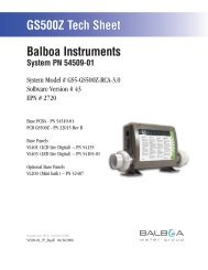
<strong>EL8</strong>000 Mach 3 Tech Sheet<strong>Balboa</strong> InstrumentsSystem PN <strong>55064</strong>-<strong>04</strong>System Model # <strong>EL8</strong>-<strong>EL8</strong>000M3-<strong>YCAH</strong>Software Version # 32EPN # 2833Base PCBA – PN 53858-03PCB <strong>EL8</strong>000 – PN 22<strong>04</strong>1 Rev A or BHEX File – 10013432Base PanelsML900 – PN 52654-01Template used: 40575-v32_A.pdf <strong>04</strong>/15/2008<strong>55064</strong>-<strong>04</strong>_97_A.pdf 05/06/2008Page 1<strong>55064</strong>-<strong>04</strong>_97_A
System Revision HistorySystem PN EPN Date Requested By Changes Made<strong>55064</strong>-02 2130 11.27.2006 <strong>Balboa</strong> Software update to v28<strong>55064</strong>-03 n/a 07.23.2007 <strong>Balboa</strong> Software update to v30<strong>55064</strong>-<strong>04</strong> 2833 05.06.2008 <strong>Balboa</strong> Software update to v32Page 2<strong>55064</strong>-<strong>04</strong>_97_A
WWBasic System Features and FunctionsPower Requirements 240VAC, 60Hz, 48A, Class A GFCI-protected service (Circuit Breaker rating = 60A max.) System OutputsSetup 1 (As Manufactured) AV (Stereo) Mister Optional Devices Additional Options Connects to Main Panel terminal J70, J71, J72, or J73 Connects to Remote terminal J20 Connects to terminal J4 Connects to A.V. terminal J5LK-A 12VAC-BJ121 2 3W30 J38 K16J20G RBWEXP I/OREMOTEJ91J22 J24 J82SWITCHBANK B SEN. A SEN. B VACW10J36J19UVJ77U4J69ADCMJ51TV 2J18 J17 J15 J83TV 1 TST AUX. F CFGW9J21J84J73 J72 MAIN PANELS J71 J70 J31 J34 J40AUX PANELS J16Page 3<strong>55064</strong>-<strong>04</strong>_97_A
Persistent Memory and Powering UpAny time you change DIP Switches or Software Configuration Settings thataffect parameters the user can change (any filter settings, set temperaturedefault, Celsius vs Fahrenheit, 12-hour vs 24-hour time, reminderssuppression, etc), you must reset Persistent Memory for your DIP Switch orSoftware Configuration Settings changes to take effect. You should also resetPersistent Memory after loading a new file into a board (using the ESM,purchased seperately).To reset Persistent Memory: Power down. Set A12 ON (See illustration below). Power up. Wait until “ ” or “ ” is displayed on your panel.Note: If “ ” appears see section below. Set A12 OFF. (This can be done safely with power on if you use a nonconductivetool such as a pencil to push the switch back to the OFFposition. Otherwise, power down before setting A12 OFF) Power up again (if you powered down in the previous step). For all other power ups, leave A12 OFF.About Persistent Memory and Time of Day Retention:This system uses memory that doesn’t require a battery to store a varietyof settings. What we refer to as Persistent Memory stores all the UserPreferences, as well as all the filter settings, the set temperature, and theheat mode.Persistent Memory is not used for Time of Day. Time of Day needs to be“kept running” (not just stored) while the power is off, so a separate RealTime Clock feature (on all models except the EL1000) keeps track ofTime of Day while the unit is off. Time of Day Retention, and Time of DayRetention alone, is controlled by the J91 jumper. J91 must be set accordingto main system panel used.RTCEnabled(Not Jumpered)Switchbank AJ91RTCDisabled(Jumpered)J91Switchbank Bmessage on power up:If “ ” appears before (and instead of) “ ” or“ ”, you have not configured DIP Switches and/orSoftware Configuration Settings in a valid manner. This must be correctedbefore you can reset Persistent Memory.The switch numbers, jumpers, or configuration settings displayed after“ ” are ones with which the system has found a configuration problem.For example: “” would mean that the combination of how you’ve setA5 and how you’ve set B2 is not supported on this system. “ ” would mean that there is a problem with jumper J99 “ ” would mean that the combination of howyou’ve set pump 3 for 1-speed and blower for 1-speed is not supportedon this system. “ ” would mean that the combination of how you’veset DIP switches which have been assigned to pump 3 and blower is notsupported on this system.Power Up Display SequenceUpon power up, you should see the following on the display: Three numbers in a row, which are the SSID (the System SoftwareID). The third display of these numbers is the Software Version, whichshould match the version of your system. For example, if these threenumbers are , that is a Mach 3 <strong>EL8</strong>000 at version 26. If there is a Configuration Error, the message (see above) willappear at this point (and none of the messages below will display).Otherwise what comes next is: An indication of either the input voltage detected (EL1000/EL2000), orthe heater wattage range supported (<strong>EL8</strong>000/GL2000/GL8000). Heater wattage display: “ ” means the system supports a heaterfrom 1 kW to 3 kW. “ ” means the system supports a heaterfrom 3 kW to 6 kW. “ ” means the system supports a 3 kWheater only. (These ranges may be modified slightly in the case ofspecial heaters, which the next bullet covers.) Input voltage display: A system showing “ ” supports 3 kWto 6 kW heaters. A system showing “ ” supports the very sameheaters, although at 120V those heaters will function at only 1/4 oftheir 240V rated wattage. (The system shows only either “ ” or“ ” as a general indication of input voltage; it does not show theactual input voltage.) If your system is using a special type of heater, a display such as “ ”may appear next. If your system is using the generic <strong>Balboa</strong> heater, noheater type display will appear. “ ” or “ ” will appear to signal the start ofPriming Mode.At this point, the power up sequence is complete. Refer to the User Guidefor the ML Series panel on your system for information about how the spaoperates from this point on.Page 4<strong>55064</strong>-<strong>04</strong>_97_A
Wiring Configuration and DIP SettingsSetup 1 (As Manufactured) (Stereo) FUSE 30A CLASS GK7BALBOA INSTRUMENTS, INC.MADE IN U.S.A.<strong>EL8</strong>000 Mach 3COPYRIGHT 2006P/N 22<strong>04</strong>1_BF6TORQUERANGEFOR TB1:27-30 IN. LBS.K4J90J13NEUTRALWHITEHOTBLACKHOTREDF7TB1J7W2G NBLK-A120V FiberFUSE 30A CLASS GJ44J49123J12-Spd P1G N12VAC-BWHT AC (120V)J28 J52 J27 J35 J43 J23 J32J26BLK ACW1K5K13J47J66 J65 J68J64 J63 J67J58 J57 J62 J54J95 J46 J74 J75 J53 J55 J59 J60 J56 J61RED AC (240V)321J42J50K11J96J94J48K6W5W3F2K8K3J8Fiber G N Opt.12VAC-BJ9-120V J97BLK-AJ2G NJ30W14J29J25FUSE 1/2A 250V123BARCODEJ14240VTransJ39W6J89F1G NJ92J85321K12-Spd P2J11K12J76K15Circ.PumpG NW4K2J86J3J9G NMisterW7K9K14J93J5G NBLK-A 12VAC-BJ371 2 3W3012V LightREMOTEA.V.J20RTCEnabledJ38J79W8K16J91F5 FUSE 20A 250VJ4K10OzoneG NJ12G NW13F4FUSE 3A 250V2-Spd P3EXP I/OW10J36J69ADCMW15J6W12J10SpaLightNGJ77BlowerG NU4W9J84J21TRC6MAIN PANELS AUX PANELS12 VACJ73 J72 J71 J70J31J16 J34J40J81 J45 J41 J33J51J101HTR2J1005.5 kWHTR1SWITCHBANK ASWITCHBANK BJ22SEN. AJ24SEN. BJ82VACJ19UVTV 2J18 J17 J15 J83TV 1 TST AUX. F CFGWARNING: Main Power to system should be turned OFF BEFORE adjusting DIP switches.WARNING: Persistent Memory (A12) must be RESET to allow new DIP switch settings to take effect. (See Persistent Memory page)A1, Test Mode OFFA2/A3, No Four H.S. H.S.Pumps w/HeaterA4, 12 Hour TimeA5, Degrees FA6, Short Timeouts123J49120V/240VFiber Lightand WheelSwitchbank AJ47A7, Cleanup Cycle OFFA8, 1Hr O3 Disable OFFA9/A10,No Circ PumpA11, Ozone w/P1 lowA12, Memory ONB1, Pump 2 2-SpeedB2/B3, Single SpeedBlower No Blower (On/Off)B4, F/O Light ON OFFB5, Pump 4 OFFB6, Scrunching OFFSwitchbank B3 13 Spa Light RTCJ29J39 J3712V Enabled2 22J9J2 withBlack AC Pump 1 LowJ911 311 2 3B7, Spa Dimmable Light On/Off LightB8, Spa FO & Light Spa Light ButtonB9, Pump 3 2-speedB10, Pump 3 Enabled DisabledB11, Mister Enabled DisabledB12, Mist Aux Pnl OFFPage 5J83SSID #10013432Config SettingsDisabledWiring Color Key120 Volt Connections240 Volt ConnectionsBlack AC Jumpers12 Volt ConnectionsRelay Control WiresBoard Connector Key1 Typically Line voltage2 Typically Line voltage for 2-speed pumps3 Neutral (Common)4 GroundNote flat sides in connector<strong>55064</strong>-<strong>04</strong>_97_A
DIP Switches DefinitionsWARNING:Setting DIP switches incorrectly may cause abnormal system behavior and/or damage to system components.Refer to Switchbank illustration on Wiring Configuration page for correct settings for this system.Contact <strong>Balboa</strong> if you require additional configuration pages added to this tech sheet.DIP Switchbank A KeyA1 ............Test Mode (normally Off)Table 1 # of Hi-SpeedA2 and A3..........Control amp draw requirements. See Table 1Pumps/BlowerA4* ............In“ON” position, displays time in 24 hours (military\European time)Before Heat Disabled............In“OFF” position, displays 12 hour timeA2 A3A5* ............In“ON” position, displays temperature in CelsiusOFF OFF 0............In“OFF” position, displays temperature in Fahrenheit* Sets default for user preferences - only applies when persistent memory is reset (A12 On)ON OFF 1during power-upOFF ON 2A6 ............In“ON” position, Equipment timeout 30 minutes (4 hours for Pump 1 Low) ON ON Up to 4............In“OFF” position, Equipment timeout 15 minutes (2 hours for Pump 1 Low)A7 ............In“ON” position, Cleanup Cycle – 30 minutes after spa use/timeout, Pump 1 Low & Ozone run for 1 hour............In“OFF” position, NO Cleanup CycleA8 ...........In “ON” position, Ozone suppressed for 1 hour after pump or blower button press...........In“OFF” position, NO Ozone suppressionA9 and A10.........Circ Pump Behavior settings. See Table 2Table 2Circ PumpA11 ............In“ON” position (non-circ mode operation) Pump 1 is two-speed, Ozone is ON A9 A10 Behaviorin Filter & Cleanup Cycles only (in any circ mode), Pump 1 is one-speed,OFF OFF No Circ PumpOzone is ON with Circ PumpON OFF 24 Hr............In“OFF” position (non-circ mode operation) Pump 1 is two-speed, Ozone isON with Pump 1 LowOFF ON 24 Hr w/3°F Shut-Off(in any circ mode) Pump 1 is two-speed, Ozone is ON with Circ PumpON ON Acts like Pump 1 LowA12 ............Persistent Memory Reset (used when the spa is powering up)(Filter Cycles, Polls)DIP Switchbank B KeyB1 ...........In“ON” position, single-speed Pump 2...........In“OFF” position, two-speed Pump 2B2 and B3..........Blower Speeds. See Table 3B4 and B8 .........Fiber Optic and Color wheel control; Spa Light EnableNote: The Light button on an ML900 panel is a SpaLight button.The Light button on most other panels is an EitherLight button.B5B6B7 ...........In“ON” position, Spa Light operation is On/Off...........In“OFF” position, Spa Light operation is dimmableB9 ...........In“ON” position, single-speed Pump 3B10B11B12............Pump 4 enable when On. Jets 4 replaces Blower on Aux panel...........In“ON” position, Alternate Panel layout(ML900 scrunching enabled; ML550 and ML700Jets 3 replaces Blower)B4 OFF...........In“OFF” position, Normal Panel layout...........In“OFF” position, two-speed Pump 3...........In“ON” position, Pump 3 enabled (Jets 3 replacesLight button on Aux panel)...........In“OFF” position, Pump 3 disabledB4 ON...........In“ON” position, Mister enabled...........In“OFF” position, Mister disabled...........In“ON” position, Mister or Option replaces Blower button on Aux panels...........In“OFF” position, no button replacement on Aux panelsTable 3B2 B3 Blower SpeedsOFF OFF 0 (No Blower)ON OFF 1 (on/off)OFF ON 2ON ON 3B8 OFFB8 ONNo separately-controlled fiber light; spa light enabled on bothSpaLight and EitherLight buttons; fiber light (not wheel) comes onwith spa light (at any intensity)No separately-controlled spalight; fiber light enabled onboth FiberLight and EitherLightbuttons; spa light comes on withfiber lightSpa light and fiber light eachseparately controlled; fiber lightenabled on both FiberLight andEitherLight buttons; spa lightenabled on SpaLight buttons onlyPage 6<strong>55064</strong>-<strong>04</strong>_97_A
Jumper DefinitionsWARNING:Setting DIP switches incorrectly may cause abnormal system behavior and/or damage to system components.Refer to Switchbank illustration on Wiring Configuration page for correct settings for this system.Contact <strong>Balboa</strong> if you require additional configuration pages added to this tech sheet.Jumpers KeyJ29J37J39J47J49J91.........Jumper on Pins 1 and 2 will power J9-pin 1 (Mister) at 12 Volts AC.Jumper on Pins 2 and 3 will power J9-pin 1 (Mister) at 120/240 Volts AC.Note: W4 controls voltage on return line of J9-pin 3 and must be set for the same voltage..........Jumper on Pins 1 and 2 will power one leg of J10-pin 2 (Spa Light) at 120/240 Volts AC.Jumper on Pins 2 and 3 will power one leg of J10-pin 2 (Spa Light) at 12 Volts AC.Note: W9 controls voltage on the return line of J10-pin 1 and must be set for the same voltage..........Jumper on Pins 1 and 2 will power J2 pin 2 with Pump 1 Low.Jumper on Pins 2 and 3 will power J2 pin 2 with the Circ Pump.Note: W6 controls voltage on common line of J2-pin 3.........Jumper on Pins 1 and 2 will power J8 pin 2 (Fiber Optic Light) and J7 at 120/240 Volts AC.Jumper on Pins 2 and 3 will power J8 pin 2 (Fiber Optic Light) at 12 Volts AC.Note: J47 and J49 must be set for the same voltage. W5 controls voltage on return line of J8-pin 3 andmust be set to the same voltage..........Jumper on Pins 2 and 3 will power J8 pin 1 (Fiber Optic Wheel) at 120/240 Volts AC.Jumper on Pins 1 and 2 will power J8 pin 1 (Fiber Optic Wheel) at 12 Volts AC.Note: J47 and J49 must be set for the same voltage. W5 controls voltage on return line of J8-pin 3 andmust be set to the same voltage..........Jumper on 1 Pin only enables Real Time Clock function, for use with time capable panels.Jumper on Pins 1 and 2 will disable RTC function, for use with non-time capable panels.Page 7<strong>55064</strong>-<strong>04</strong>_97_A
Ozone ConnectionsOzone Connector Voltage: The EL circuit board is factory configured to deliver a preset voltage (120Vor 240V) to the on-board ozone connector (J4). See the ratings table on the wiring diagram attached tothe cover of the enclosure for the configured voltage. For 240V output W13 connects to Red AC and for120V output W13 connects to White AC.The voltage to the ozone connector can be changed in the field if required. W13 just needs to be set forthe required voltage.<strong>Balboa</strong> Ozone Generator: If the board is set up to operate a 120V ozone generator, the connector on theozone generator is likely to be configured correctly, but should be compared to the illustration below.If a 240V ozone generator is required, be sure the red wire in the ozone cord is positioned in theconnector next to the green ground wire as described below.Note: A special tool is required to remove the pins from the connector body once they are snapped inplace. Check with your <strong>Balboa</strong> Account Manager for information on purchasing a pin-removal tool.<strong>Balboa</strong> Ozone connector configuration for 120V 60HzLine - Black conductorUse this slot for the leftover Red conductorCommon - Install the White conductor here for 120V ozoneGround (Green) conductorBG<strong>Balboa</strong> Ozone connector configuration for 240V 60HzLine - Black conductorUse this slot for the leftover White conductorCommon - Install the Red conductor here for 240V ozoneGround (Green) conductorFlat sides of sockets as shownBGW13 wire determines voltageJ93FUSE 10A 250VF59 J79J5 J4K10W15J6TRC6Line - Black conductorUse this slot for the leftover conductorCommon - Red for 240V or White for 120V ozone (See W13 wire)Ground (Green) conductorG NW8W13F4FUSE 3A 250VW12J10G NG NW9J21NELSJ16 12 VACJ81 J45 J41 J33Page 8<strong>55064</strong>-<strong>04</strong>_97_A
Panel ConfigurationsNote: RTC jumper (J91) on Main PCBA must be OFF (1 pin only)Time Warm Jets 1 Jets 2 Jets 3 OptionTIME CAPABLEF1F2PLTLMode/Prog CoolInvert FiberLight BlowerML900PN 52654-01 with Overlay PN 40026 Connects to Main Panel terminal J70, J71, J72, or J73Page 9<strong>55064</strong>-<strong>04</strong>_97_A