
Create successful ePaper yourself
Turn your PDF publications into a flip-book with our unique Google optimized e-Paper software.
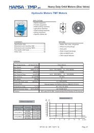
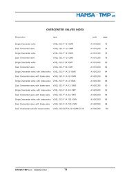
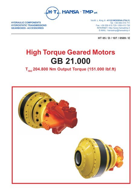
HYDRAULIC COMPONENTSHYDROSTATIC TRANSMISSIONSGEARBOXES - ACCESSORIESVia M. L. King, 6 - 41122 MODENA (ITALY)Tel: +39 059 415 711Fax: +39 059 415 729 / 059 415 730INTERNET: http://www.hansatmp.itE-MAIL: hansatmp@hansatmp.itHT 05 / D / 107 / 0509 / EHigh Torque Geared MotorsGB 21.000T ISO204.800 Nm Output Torque (151.000 lbf.ft)
High Torque Geared MotorsGB 21.000CONTENTSGeneral Information 4 - 8Gearbox Selection Method 9 - 10Motor Selection Method 10Motor Mounting Instruction 11 - 12Gearbox Mounting Instruction 13 - 14Lubrication 15Motor Selection Card 16Gearbox Selection Card 17Order Code 18Installation Drawings 19 - 23Technical Characteristics - Load on Shaft 24Accessories 25Weight Table 25Oil Quantity Table 25HT 05 / D / 107 / 0509 / E Pag. 3
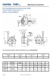
GEARED MOTOR UNITS - General InformationSummary descriptionHigh Torque Geared MotorsGB 21.000The <strong>HANSA</strong>-<strong>TMP</strong> range of “GB” high torque Single or Multi-stages Reduction Planetary gear boxescombined with Kawasaki / Staffa single, dual or variable displacement radial piston motors comprises 14models offering ISO torque from 70.000 up to 1.200.000 Nm (from 52.000 up to 885.000 lbf.ft).The “GB” range of gear boxes is available from 1 up to 5 stages with ratio from 3,43:1 up to 3794:1.This versatile range of gear boxes accept standard Kawasaki / Staffa motors allowing the system designerto select the right motor and gear box to optimise his circuit pressure and flow against the torque and speedrequirements of his transmission.The output shaft of the “GB” planetary gear boxes include: splined male and female, parallel keyed and shrink disc.Main features- Flexibility in service: modular concept enables drive to be uprated in service with minimum inconvenience.- Constant torques: throughout the infinitely variable speed range.- Lower maintenance costs: modular system enables motors to be overhauled without disturbing the system.- Uniform running at low speeds: speeds at fractions of one R.P.M. can be achieved smoothly.- Excellent gear life: materials used are aimed at maximum running hours.- Modular design: plug in concept enables standard motors to be fitted from existing stock.- Complete transmission: full range gives a balanced transmission package for both automotiveand general industrial drives.Pag. 4HT 05 / D / 107 / 0509 / E
GEARED MOTOR UNITS - General Information (continued)Symbols and units of measurementHigh Torque Geared MotorsGB 21.000SYMBOLS and UNIT of MEASURESymbol Unit DescriptionF r2 N Output shaft radial loadF a2 N Output shaft axial loadf s _ Service factori e _ Effective reduction ratioi n _ Nominal ratiok f _ Output support life correction factorL min mm. Torque arm lenghtsMt max Nm Shrink disk torquen 1 n/min. Input speedn 1 x h n/min. x h Input duration indexn 2 max n/min. Max output speedn 2 n/min. Rated output speedh h Working Time in hoursh i _ Time percentagep bar PressureP 1 kW Input powerP 2 kW Output powerP d kW Dissipated powerP t kW Thermal powerQ lt/min. Oil flowT f Nm Static braking torqueT 1 Nm Input torqueT 2 Nm Output torqueT eq Nm Equivalent torqueT ISO Nm ISO limit torqueT cont. Nm Continuous torqueT max. Nm Maximum torqueT imp. Nm Impulse torqueT M Nm Max. load torqueV cm 3 DisplacementX mm. Reaction distancem _ Mechanical efficiencyv _ Volumetric efficiencyt _ Total efficiencyCONVERSION TABLELength1 mm. = 0,03937 in.1 in. = 25,4 mm.1 mm. = 0,000328 ft1 ft = 304,8 mm.Force1 kp = 9,81 N1 N = 0,102 kp1 kp = 2,2046 lbf1 lbf = 0,4536 kpTorque1 Nm = 8,85 lbf. in1 lbf.in = 0,1129 Nm1 Nm = 0,737 lbf.ft1 lbf.ft ff= 1,355 NmAngular speeed1 n / min. = 0,1047 rad. /sec.1 rad. / sec. = 9,549 n / min.Power1 kW = 1,341 HP1HP = 0,7457 kW1 kW = 1,3596 PS1 PS = 0,7355 kW1 kW = 101,972 kp.m / sec.1 kp.m / sec. = 0,0985 kWPressure1 bar = 0,981 kp / cm21 kp / cm 2 = 1,02 bar1 bar = 14,5 PSI1 PSI = 0,0689 bar1 Mpa = 145 PSI1 PSI = 0,00689 MpaCapacity / Flow rate1 lt / min. = 0,22 Imp. GPM1 Imp GPM = 4,546 lt / min.1 lt / min. = 0,2642 US GPM1 US GPM = 3,785 lt / min.Volume / Displacement1 cm 3 = 0,062 in31 in 3 = 16,387 cm3Temperature1 °C = 5/9 (°F-32)1 °F = 32+ 9/5 °CHT 05 / D / 107 / 0509 / E Pag. 5
GEARED MOTOR UNITS - General Information (continued)TorqueHigh Torque Geared MotorsGB 21.000T ISO= limit torque: Transmittable torque of gearbox, with continuous operation, calculated in accordance toISO DP 6336 for gears and safety factor 1.This torque corresponds to a life duration equal to 50x10 6 cycles of the most stressed element(theoretically considered unlimited by the ISO DP 6336; horizontal curve in the Wöhler fatigue diagram).This torque does not represent a duration but it is useful for a quick selection of a maximum size of thegearbox.T cont= continuous torque: Transmittable torque of gearbox with continuous operation, that guarantees a durationof "h" hours, with a gearbox output rotation speed of "n 2".T contis expressed as a function of the product n 2x h .T eq= equivalent torque: T eqrepresents the value of a constant torque which determines the same duration inhours of the torque induced by the work cycle.Known as T 21...T 2nthe torque transmitted by the gearbox at the output speed n 2ìfor a time durationin hours of h ì, the equivalent torque is:whereT max= maximum torque: Value of maximum torque that the gearbox can transmit for short period of time.T max= 1,25 x T contwhen n 2x h = 50.000In application with high number of cycles and a torque near the maximum, one must take into account anopportune safety factor. In this case it is recommended that our Tech. Dpt. be contacted.T imp= impulsive torque: Value of static torque or an istantaneous peak load that the gearbox can withstand:T imp= ( from 1,25 to 1,9 ) x T contwhen n 2x h = 50.000Each coefficient is given in the life time table.Efficiencyn m= mechanical efficiency: ratio between the output power and input power.Normally it is considered to be equal to 0,97 - 0,98 per reduction stage that makes up the gearbox;it depends upon various factors, of which speed, torque, ratio, working position and lubrication.Pag. 8HT 05 / D / 107 / 0509 / E
High Torque Geared MotorsGB 21.000GEARBOX SELECTION METHODSelectionOnce established the selection criteria, which can be defined using an ISO or AGMA safety factor, based upon theclass according to the F.E.M. standard or by expressing a minimum life duration, the equivalent output torque T eqis determined as well as the required duration and the reduction ratio. Using these criteria the gearbox is selected.- safety factor ISO / AGMA: the gearbox must guarantee the requested theoretical lifetime.- F.E.M. class: the gearbox must guarantee that the requested theoretical lifetime correspond to that indicated bythe F.E.M. class as a function of the max and T eq.- Life duration: the gearbox must have a life duration greater than that required as a function of T eq .For example, table on page 17 shows the continuous torques as a function of gearbox size and the reduction ratio.The start-up torque must not exceed the gearbox maximum torque.The number of start-up per hour and the hours of operation per day must be carefully considered.If the output speed is constantly less than 1 n/min., there may be problems with the lubrication of the outputstage, which could reduce the calculated theoretical life. Contact our Tech. Dpt. for a proper selection.DURATION REQUIRED BY THE FEM CLASSESclassduration withT eq
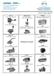
GEARBOX SELECTION METHOD (continued)VerificationsHigh Torque Geared MotorsGB 21.000Gearbox output support:For each gearbox the dynamic radial loads according to ISO 281 for a duration of L10 corresponding to n 2x h = 100.000are shown in the diagrams.For different durations, applicable radial loads can be obtained by multiplying the values in the diagrams by the correctionfactor kf.With regard to eventual axial loads, one must ensure that they do not exceed the maximum allowed values.Output torque: the output torque must never exceed T max.In the event that brakes are mounted on the gearbox or the motor, one must ensure that the braking torque does notexceed the maximum torque of the gearbox itself multiplied by 1,1; with regard to the real braking torque, it is alsonecessary to consider the efficiency of the gearbox.Input speed: must not exceed the maximum gearbox input speed.Thermal power: in the event that the installed power is greater than the thermal power of the gearbox,it is necessary to provide a cooling circuit or to select a larger gearbox.The power to dissipate is: P d= ( P 2- P t)x(1-ç m)where P 2is the power transmitted by the gearbox.In the event that thermal power is not exceeded, but the application is particularly heavy, it may be necessary toinstall an oil circulation and filtering system.MOTORS SELECTION METHODHydraulic DrivesKnowing the hydraulic circuit pressure, from which the Dp of the motor can be obtained, the torque T 1, the speed n 1required at the input of the gearbox, the hydraulic motor capacity must be greater or equal to:where n mis the mechanical efficiency.The necessary supply flow rate is:where n vis the volumetric efficiency of the motor.Please use the following table as a guide for hydraulic motor selection.HYDRAULIC MOTORSUse medium - heavyPressure - bar 175 - 250Type of motor radial pistonSpeed - n/min. < 500 m 0,90 v 0,96Pag. 10HT 05 / D / 107 / 0509 / E
High Torque Geared MotorsGB 21.000MOTOR MOUNTING INSTRUCTIONCircuit and Application NotesMineral Oil recommendationsThe fluid should be a good hydraulic grade, non-detergent Mineral Oil.It should contain anti-oxidant, antifoam and demulsifying additives. It should contain antiwear or EP additives.WARNING: Automatic transmission fluids and motor oils are not recommended.Temperature limitsAmbient min. -30°C (-22°F)Ambient max. + 70°C (158°F)Max. operating temperature range.Min -20°C (-4°F) +10°C (50°F)Max. + 80°C (175°F) +54°C (130°F)Note: To obtain optimum service life from both fluid and hydraulic systems components, a fluidoperating temperature of 40°C is recommended.FiltrationFull flow filtration (open circuit), or full boost flow filtration (closed circuit) to ensure system cleanliness toISO 4406/1986 code 18/15/12 (Class 7 NAS 1638) or cleaner.Start - upFill the motor crankcase with clean system fluid.Noise levelThe airborne noise level is less than 66.7 dB(A) DIN (dB (A) NFPA) through the “continuous” operating envelope.Where noise is a critical factor, installation resonances can be reduced by isolating the motor by elastomeric meansfrom the structure and the return line installation.Potential return line resonances originating from liquid borne noise can be further attenuated by providing a return lineback pressure of 2 to 5 bar.HT 05 / D / 107 / 0509 / E Pag. 11
MOTOR MOUNTING INSTRUCTION (continued)High Torque Geared MotorsGB 21.000Assembly Positions - Crankcase DrainMotor Axis Horizontal.The recommended minimum pipe size for drain linelengths up to approx. 5m is 12.0mm 1/2” bore.Longer drain lines should have their bore sizeincreased to keep the crankcase pressurewithin limits.The crankcase drain must be taken from a positionabove the horizontal centre line of the motor to ensurelubrication of the shaft bearings.Connect to a drainport above motorcentre lineMotor Axis Vertical, shaft down.The piping, from any drain port, must be takenabove the level of the motorcase to ensure goodbearing lubrication.The drain line should be run above the level of theuppermost bearing.If there is a risk of syphoning then a syphon breakershould be fitted.Motor Axis Vertical, shaft up.Specify “V” within the model code for extra drainport, G1/4” (BSPF). Connect this port into themain drain line downstream of a 0.35 bar checkvalve to ensure good bearing lubrication.The piping arrangement must not allow syphoningfrom the motorcase.Additional drain portG1/4" (BSPF)An additional G 1/4" (BSPF) drain port is providedwhen “V” (shaft vertically upwards) designator is givenafter the shaft type (see Ordering Code).This additional drain should be connected into the mainmotor casing drain line downstream of a 0.35 barcheck valve to ensure lubrication of the upper bearing(see installation diagram).Standard drain port3/4" - 16 UNF0.35 barPag. 12HT 05 / D / 107 / 0509 / E
High Torque Geared MotorsGB 21.000GEARBOX MOUNTING INSTRUCTIONAssembly PositionsIn order to provide a complete definition of the constructive form of the gearbox, the assembly position must bedefined.Based upon the position it is also possible to identify the oil filling, level and drain plugs.InstallationGearbox with flange and male shaft:The connecting surface should be flat, unpainted, machined and perpendicular to the rotation axis.The following table shows the required spigot with their representative tolerances.Diameter mm 500 -630 630 -800 800 -1.000 1.000 - 1.250Tollerancemm+ 0,076+ 0,186+ 0,080+ 0,205+ 0,086+ 0,226+ 0,098+ 0,263Gearbox with female splined shaft:The female version gearboxes are not suitable for supporting output radial loads, it is therefore extremely important toproperly align between the gearbox and the driven shaft.It is also necessary to check that driven shaft does not undergo bending during the working phases.Torque arm mounted gearbox:It is necessary to carry out an anchorage of the torque arm that is not constrained to the axis of the gearbox.The anchorage must also be suitable shock proof.In the dimension tables of each gearbox one can find the minimum torque arm lenght needed to carry out theapplication correctly.ScrewsizeTorqueNmTIGHTENING TORQUES AND CLAMPING FORCESClass 8.8 Class 10.9 Class 12.9ForceNTorqueNmForceNTorqueNmForceNM 10 50 27.000 70 39.000 85 46.000M 12 85 39.500 120 57.000 145 67.000M 14 136 54.500 195 78.000 230 92.000M 16 213 75.000 310 105.000 360 127.000M 18 300 93.500 420 130.000 495 153.000M 20 430 120.000 600 165.000 700 195.000M 22 580 148.000 810 210.000 965 245.000M 24 730 170.000 1.000 240.000 1.200 285.000M 27 1.080 225.000 1.500 315.000 1.800 370.000M 30 1.470 270.000 2.050 385.000 2.450 455.000M 33 2.000 335.000 2.750 460.000 3.300 550.000M 36 2.550 390.000 3.500 535.000 4.500 645.000HT 05 / D / 107 / 0509 / E Pag. 13
GEARBOX MOUNTING INSTRUCTION (continued)LubricationHigh Torque Geared MotorsGB 21.000WARNING: The gearbox is supplied without lubrication oil.Before use, the gearbox must be filled with oil up to the level indicated using one of the lubricating oils recommended.The choice and the quantity of oil will be referred to the installer / user based upon the type of application.PaintThe supplied gearboxes are not painted. A few parts are treated with a base layer of water soluble epoxy ester red oxide.The customer must take care to carry out the surface treatment using a paint that is compatible with the base layer.O-Rings must be protected during the painting.Installation of flange motorThe installation of the motor to the coupling flange supplied is a particularly simple operation, but it must be carried outfollowing some important suggestions:- Lubricate the motor shaft and the coupling with a light film of grease or anti-seizure lubricant.- Ensure that the motor rests freely on the gearbox fixing flange without forcing on either the shaft or the spigot.- Tighten the fixing screws as indicated to the table on the previous page.STORAGEThe gearboxes must not be stored in the open or in direct contact with the ground. For long time periods they must bestored full of oil, with external worked parts covered with grease and the coupling surfaces protected with anti-oxidantagents.We recommend to operate the gearboxes (a complete rotation of the output shaft is sufficient) without load at least onceevery two months. For further information regarding storage, please refer to the maintenance and operating manual.Pag. 14HT 05 / D / 107 / 0509 / E
High Torque Geared MotorsGB 21.000GEARBOX LUBRICATIONType of lubricantThe gearboxes lubrication is carried out by an oil bath; before the first start-up it is necessary to fill it with oil, whilstensuring visually using the level plug that the correct level is reached. This operation requires particular attention and thelevel must be re-checked after a few minutes of operation to ensure it has been carried out correctly. The quantities of oilshown in the catalogue are purely indicative and can vary in function of the reduction ratio and the type of gearbox input.Choice of oilAny type of oil for mechanical transmission can be used with EP additives with viscosity classes from VG 68to VG 220 according ISO 3448 or SAE 80-90 W according SAE J 306-81.In particular cases we can use oils with different viscosities, in this event please contact our Tech. Dpt.The oil viscosity must be chosen as a function of the ambient temperature of the gearbox.For gearboxes that have to operate at high ambient temperatures or where there are strong thermal excursions, the useof synthetic based oils is recommended.In gearboxes with vertical installation and continuous operation, the oil can undergo excessive overheating ; in this casean external expansion tank is necessary to enable the oil to expand due to the thermal action.Oil changeThe oil change must be carried out after the first 150 hours of effective work, and then after the following 2000 to 4000hours of operation, depending on the working condition and at least once a year. To facilitate the emptying of the gearbox,we advise that the oil change is carried out while the gearbox is warm. The internal parts must be washed with suitableliquid before the new oil introduction. Different oils must not be mixed together: this is particularly true for mineral andsynthetic oils.After the gearbox has been operated, the oil level must be checked periodically and re-filling carried out if necessary.Oil quantityThe oil quantities required for proper lubrication can be found in page 25.SAE J-306-81 VG ISO 3448SAE 80W 68SAE 85W 150SAE 90W 220OIL VISCOSITYOPERATING TEMPERATURE °CAMBIENT TEMPERATURE °C-20° -10° 0° 10° 20° 30° 40° 50° 60° 70° 80° 90° 100°AmbientTemperatureViscosityMOBILAGIPBPCASTROLELFESSOIPSHELLTOTALMineral Oil-15°C / +25°CMineral Oil-5°C / +40°CSyntetic Oil-25°C / +80°CISO 3448 VG 100 VG 150 VG 150 - 220IV min. 95 95 165MOBILGEAR 627 MOBILGEAR 629 MOBILGEAR SHC XMP 220BLASIA 100 BLASIA 150 BLASIA SX 220ENERGOL GR XP 100 GR XP 150 ENERSYNT HTX 220ALPHA SP100 ALPHA SP150 ALPHASYNT 220REDUCTELF SP100 REDUCTELF SP150 ORITIS 125 MSSPARTAN EP100 SPARTAN EP150 SPARTAN SYNT EP220MELLANA 100 MELLANA 150 TELESIA OIL 150OMALA OIL 100 OMALA OIL 150 OMALA OIL HD 200CARTER EP100N CARTER EP150 CARTER SH 220HT 05 / D / 107 / 0509 / E Pag. 15
High Torque Geared MotorsGB 21.000MOTOR SELECTION CHARTFixed Displacement Radial Piston Hydraulic Motors HMB SeriesMotorModelDisplacementcm 3 /nRatedPressurebarIntermittentPressurebarContinuousSpeedn/min.Dual Displacement Radial Piston Hydraulic Motors HMC SeriesContinuousPowerkWHMB 010 188 207 240 500 25 40HMB 030 442 207 290 450 42 73ApproxWeightkgHMB 045 740 250 290 400 60 120HMB 060 983 250 290 300 80 144HMB 080 1.344 250 290 300 100 144HMB 100 1.639 250 290 250 110 144HMB 125 2.050 250 290 220 100 217HMB 150 2.470 250 290 220 115 265HMB 200 3.080 250 290 175 130 265HMB 270 4.310 250 290 125 140 420HMB 325 5.310 250 290 100 140 429HMB 400 (4") 4816.800 250 290 120190HMB 400 (4-1/2") 510HMB 700 11.600 250 290 100 240 1.050Displacement Rated Intermittent Continuous Continuous ApproxMotormin/max. * Pressure Pressure Speed ** Power *** WeightModelcm 3 /n barbarn/min.kW kgHMC 030 49 - 492 207 241 1.000 - 450 60 100HMC 045 81 - 737 250 275 1.000 - 450 99 150HMC 080 82 - 1.475 250 275 1.000 - 300 138 172HMC 125 82 - 2.048 250 275 1.000 - 190 135 235HMC 200 80 - 3.080 250 275 1.000 - 175 174 282HMC 270 160 - 4.588 250 275 1.000 -120 189 450HMC 325 492 - 5.326 250 275 350 - 100 189 460* Intermediate displacements can be made available to special order** At min / max. displacement*** At max. displacementDual Displacement Radial Piston Hydraulic Motors HPC Series (Low friction components)Displacement Rated Intermittent Continuous Continuous ApproxMotormin/max. * Pressure Pressure Speed ** Power *** WeightModelcm 3 /n barbarn/min.kW kgHPC 080 164 - 1.600 250 275 1.000 - 270 165 172HPC 125 164 - 2.048 250 275 1.000 - 190 202 235HPC 200 164 - 3.087 250 275 1.000 - 175 261 282HPC 270 328 - 4.588 250 275 1.000 -120 278 450HPC 325 492 - 5.326 250 275 350 - 100 278 460* Intermediate displacements can be made available to special order** At min. / max. displacement*** At max. displacement, 250 bar, with flushingFor motor dimensions see specific catalogues.Pag. 16HT 05 / D / 107 / 0509 / E
High Torque Geared MotorsGB 21.000GEARBOX SELECTION CHARTGB 21000NumberofStagesGearboxtypeRatioieOutputTorqueT ISONmThermalPowerPtkWn 2 x h10.000n 2 x h25.000n 2 x h50.000T cont. - (Nm)n 2 x h100.000n 2 x h500.000n 2 x h1.000.000n 2 x h2.000.000Max.InputSpeedn 1n/min.3,68 204800 279283 222812 180980 147001 90704 73674 59842 14001 GB 210011174,94 156300 201066 175044 157621 141966 87598 71151 57793 140014,72 204800 279283 222812 180980 147001 90704 73674 59842 20002 GB 21002 17,17 204800 73 248920 222812 180980 147001 90704 73674 59842 200023,06 156300 201066 175044 157621 141966 87598 71151 57793 200058,88 204800 279283 222812 180980 147001 90704 73674 59842 235068,69 204800 248920 222812 180980 147001 90704 73674 59842 235076,54 204800 279283 222812 180980 147001 90704 73674 59842 23503 GB 21003 89,30 204800 53 248920 222812 180980 147001 90704 73674 59842 2350107,33 204800 248920 222812 180980 147001 90704 73674 59842 2350123,53 156300 201066 175044 157621 141966 87598 71151 57793 2350144,12 156300 201066 175044 157621 141966 87598 71151 57793 2350209,76 204800 279283 222812 180980 147001 90704 73674 59842 2500244,58 204800 279283 220893 179420 145734 89922 73040 59326 2500272,69 204800 279283 222812 180980 147001 90704 73674 59842 2500317,95 204800 279283 222812 180980 147001 90704 73674 59842 2500350,34 204800 248920 222812 180980 147001 90704 73674 59842 2500390,37 204800 279283 222812 180980 147001 90704 73674 59842 25004 GB 21004 455,44 204800 42 248920 222812 180980 147001 90704 73674 59842 2500520,05 204800 248920 222812 180980 147001 90704 73674 59842 2500547,40 204800 248920 222812 180980 147001 90704 73674 59842 2500625,06 204800 248920 222812 180980 147001 90704 73674 59842 2500736,00 204800 248920 222812 180980 147001 90704 73674 59842 2500839,27 156300 201066 175044 157621 141966 87598 71151 57793 2500988,24 156300 201066 175044 157621 141966 87598 71151 57793 2500755,14 204800 279283 222812 180980 147001 90704 73674 59842 3100880,48 204800 279283 220893 179420 145734 89922 73040 59326 3100981,68 204800 279283 222812 180980 147001 90704 73674 59842 31001039,46 204800 279283 220893 179420 145734 89922 73040 59326 31001144,63 204800 279283 222812 180980 147001 90704 73674 59842 31001304,42 204800 279283 220893 179420 145734 89922 73040 59326 31005 GB 210051405,35 204800 279283 222812 180980 147001 90704 73674 59842 3100351659,09 204800 279283 222812 180980 147001 90704 73674 59842 31001894,46 204800 279283 222812 180980 147001 90704 73674 59842 31002082,00 204800 279283 222812 180980 147001 90704 73674 59842 31002384,64 204800 279283 222812 180980 147001 90704 73674 59842 31002602,50 204800 248920 222812 180980 147001 90704 73674 59842 31002763,69 204800 279283 222812 180980 147001 90704 73674 59842 31003128,00 204800 248920 222812 180980 147001 90704 73674 59842 3100HT 05 / D / 107 / 0509 / E Pag. 17
High Torque Geared MotorsGB 21.000ORDER CODEGB 2100 3 H S 58,88 ST AA B5 HMB 150Gearbox GB SeriesGearbox frame size:2100..Motordisplacement:See motorselection tableNumber of stages:1 - 2 - 3 - 4 - 5Output version:Motor type:HMBHMCHPCH - Heawy duty flange type output supportWorking position:Output shaft:S - Male splined shaftB5 - HorizontalV1 - Vertical shaft downV3 - Vertical shaft upC - Parallel kejed shaftK - K1 - Parallel special shaftFS - Female splined shaftHQ - Shrink disc shaftMotor adapter configuration:Radial Piston MotorReduction ratio:Please write the exact ratio as shown on the selection tablesDirect input:STPag. 18HT 05 / D / 107 / 0509 / E
High Torque Geared MotorsGB 21.000GB 21000 - Installation Drawing285150HT 05 / D / 107 / 0509 / E Pag. 19
High Torque Geared MotorsGB 21.000GB 21000 - Installation Drawing2852251/8"Gg6Pag. 20HT 05 / D / 107 / 0509 / E
High Torque Geared MotorsGB 21.000GB 21000 - Installation Drawing285H7HT 05 / D / 107 / 0509 / E Pag. 21
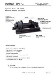
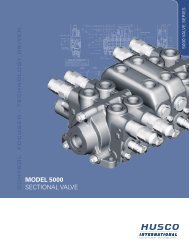
High Torque Geared MotorsGB 21.000GB 21000 - Installation DrawingGB 21002 HS.......HMB.....Dimension depending on motor type and sizeCMounting face562,5196BAGearbox type Motor type A B CHMB 125 475 132 345GB 21002HMB 150 - 200 475 132 442HMB 270 - 325 575 138 460HMB 400 480 182 565For motor dimensions see specific catalogues: HMB - HMC - HPC.For different sizes and types of motors please consult our Tech. Dpt.Pag. 22HT 05 / D / 107 / 0509 / E
High Torque Geared MotorsGB 21.000GB 21000 - Installation DrawingGB 21003 HS.......HMB.....Dimension depending on motor type and sizeC196Mounting face669,5BAGearbox type Motor type A B CGB 21003HMB 060 - 080 - 100 370 132 345HMB 125 475 142 375For motor dimensions see specific catalogues: HMB - HMC - HPC.For different sizes and types of motors please consult our Tech.Dpt.HT 05 / D / 107 / 0509 / E Pag. 23
High Torque Geared MotorsGB 21.000GB 21000Technical Characteristics - Load on ShaftPag. 24HT 05 / D / 107 / 0509 / E
High Torque Geared MotorsGB 21.000GEARED MOTOR UNITS - AccessoriesTorque Arm BRGEARBOXTYPEVERSION Ø A Ø B Ø C D E F Ø G H H1 LGB 21000 H 710 66O 28 (36) 130 145 90 65 1300 1800 35Shrink Disk GAGEARBOXTYPEØ A Ø B CScrew DSize - class - n°TighteningtorqueT maxGB 21000 280 460 134 M 20 - 10.9 - (16) 490 Nm 270.000 NmWeight table (without motor)GearboxtypeWeightkg *GB 21001 1150GB 21002 1344GB 21003 1403GB 21004 1419GB 21005 1427* Indicative dry weightwithout motorOil quantity tableGearboxtypeOil quantity - lt *Mounting positionB5 V1 V3GB 21001 21.0 42.0 42.0GB 21002 23.4 46.8 46.8GB 21003 24.8 49.6 49.6GB 21004 25.2 50.4 50.4GB 21005 25.5 51.0 51.0* Indicative quantityHT 05 / D / 107 / 0509 / E Pag. 25
As <strong>HANSA</strong>-<strong>TMP</strong> has a very extensive range of products and some productshave a variety of applications, the information supplied may often only applyto specific situations.If the catalogue does not supply all the information required, please contact<strong>HANSA</strong>-<strong>TMP</strong>.In order to provide a comprehensive reply to queries we may require specificdata regarding the proposed application.Whilst every reasonable endeavour has been made to ensure accuracy, thispublication cannot be considered to represent part of any contract, whetherexpressed or implied.<strong>HANSA</strong>-<strong>TMP</strong> reserves the right to amend specifications at their discretion.HYDRAULIC COMPONENTSHYDROSTATIC TRANSMISSIONSGEARBOXES - ACCESSORIESVia M. L. King, 6 - 41122 MODENA (ITALY)Tel: +39 059 415 711Fax: +39 059 415 729 / 059 415 730INTERNET: http://www.hansatmp.itE-MAIL: hansatmp@hansatmp.it