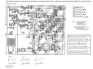
123456789012345678901234567890121234567890123456789012345678901212345678901234567890123456789012121234567890123456789012345678901212345678901234567890123456789012123456789012345678901234567890121212345678901234567890123456789012123456789012345678901234567890121234567890123456789012345678901212123456789012345678901234567890121234567890123456789012345678901212345678901234567890123456789012121234567890123456789012345678901212345678901234567890123456789012123456789012345678901234567890121212345678901234567890123456789012123456789012345678901234567890121234567890123456789012345678901212<strong>LC</strong>-<strong>20SH1E</strong>IMPORTANT SERVICE SAFETY PRECAUTIONË Service work should be performed only by qualified service technicians who arethoroughly familiar with all safety checks and the servicing gui<strong>de</strong>lines which follow:WARNING1. For continued safety, no modification of any circuitshould be attempted.2. Disconnect AC power before servicing.CAUTION: FOR CONTINUED PROTECTIONAGAINST A RISK OF FIRE REPLACE ONLY WITHSAME TYPE F6700 (1.25A, 250V), F6701 (1.25A,250V), F6702 (1.25A, 250V), F6703 (1.25A, 250V)F6704 (1.25A, 250V) AND F7701 (3.15A, 250V)FUSE.BEFORE RETURNING THE RECEIVER(Fire & Shock Hazard)Before returning the receiver to the user, performthe following safety checks:1. Inspect all lead dress to make certain that leads arenot pinched, and check that hardware is not lodgedbetween the chassis and other metal parts in thereceiver.2. Inspect all protective <strong>de</strong>vices such as non-metalliccontrol knobs, insulation materials, cabinet backs,adjustment and compartment covers or shields,isolation resistor-capacitor networks, mechanicalinsulators, etc.3. To be sure that no shock hazard exists, check forleakage current in the following manner.• Plug the AC cord directly into a 220~240 volt AC outlet.• Using two clip leads, connect a 50k ohm, 10 wattresistor paralleled by a 0.15µF capacitor in series withall exposed metal cabinet parts and a known earthground, such as electrical conduit or electrical groundconnected to an earth ground.• Use an AC voltmeter having with 5000 ohm per volt,or higher, sensitivity or measure the AC voltage dropacross the resistor.• Connect the resistor connection to all exposed metalparts having a return to the chassis (antenna, metalcabinet, screw heads, knobs and control shafts,escutcheon, etc.) and measure the AC voltage dropacross the resistor.All checks must be repeated with the AC cord plugconnection reversed. (If necessary, a nonpolarizedadaptor plug must be used only for the purpose ofcompleting these checks.)Any reading of 0.75V peak (this corresponds to 0.5mA. peak AC.) or more is excessive and indicates apotential shock hazard which must be corrected beforereturning the monitor to the owner.TO EXPOSEDMETAL PARTSDVMAC SCALE50k ohm10W0.15 µFTEST PROBECONNECT TOKNOWN EARTHGROUND12345678901234567890123456789012123456789012345678901234567890121234567890123456789012345678901212SAFETY NOTICEMany electrical and mechanical parts in <strong>LC</strong>D televisionhave special safety-related characteristics.These characteristics are often not evi<strong>de</strong>nt from visualinspection, nor can protection affor<strong>de</strong>d by them benecessarily increased by using replacement componentsrated for higher voltage, wattage, etc.Replacement parts which have these special safetycharacteristics are i<strong>de</strong>ntified in this manual; electricalcomponents having such features are i<strong>de</strong>ntified by " å"and sha<strong>de</strong>d areas in the Replacement Parts Lists andSchematic Diagrams.For continued protection, replacement parts must bei<strong>de</strong>ntical to those used in the original circuit.The use of a substitute replacement parts which do nothave the same safety characteristics as the factoryrecommen<strong>de</strong>d replacement parts shown in this servicemanual, may create shock, fire or other hazards.2
<strong>LC</strong>-<strong>20SH1E</strong>Precautions for using lead-free sol<strong>de</strong>r1 Employing lead-free sol<strong>de</strong>r"MAIN PWB" of this mo<strong>de</strong>l employs lead-free sol<strong>de</strong>r. The LF symbol indicates lead-free sol<strong>de</strong>r, and is attached onthe PWBs and service manuals. The alphabetical character following LF shows the type of lead-free sol<strong>de</strong>r.Example:L FaIndicates lead-free sol<strong>de</strong>r of tin, silver and copper.2 Using lead-free wire sol<strong>de</strong>rWhen fixing the PWB sol<strong>de</strong>red with the lead-free sol<strong>de</strong>r, apply lead-free wire sol<strong>de</strong>r. Repairing with conventionallead wire sol<strong>de</strong>r may cause damage or acci<strong>de</strong>nt due to cracks.As the melting point of lead-free sol<strong>de</strong>r (Sn-Ag-Cu) is higher than the lead wire sol<strong>de</strong>r by 40°C, we recommendyou to use a <strong>de</strong>dicated sol<strong>de</strong>ring bit, if you are not familiar with how to obtain lead-free wire sol<strong>de</strong>r or sol<strong>de</strong>ring bit,contact our service station or service branch in your area.3 Sol<strong>de</strong>ringAs the melting point of lead-free sol<strong>de</strong>r (Sn-Ag-Cu) is about 220°C which is higher than the conventional leadsol<strong>de</strong>r by 40°C, and as it has poor sol<strong>de</strong>r wettability, you may be apt to keep the sol<strong>de</strong>ring bit in contact with thePWB for exten<strong>de</strong>d period of time. However, Since the land may be peeled off or the maximum heat-resistancetemperature of parts may be excee<strong>de</strong>d, remove the bit from the PWB as soon as you confirm the steady sol<strong>de</strong>ringcondition.Lead-free sol<strong>de</strong>r contains more tin, and the end of the sol<strong>de</strong>ring bit may be easily corro<strong>de</strong>d. Make sure to turn onand off the power of the bit as required.If a different type of sol<strong>de</strong>r stays on the tip of the sol<strong>de</strong>ring bit, it is alloyed with lead-free sol<strong>de</strong>r. Clean the bit afterevery use of it.When the tip of the sol<strong>de</strong>ring bit is blackened during use, file it with steel wool or fine sandpaper.Be careful when replacing parts with polarity indication on the PWB silk.Lead-free wire sol<strong>de</strong>r for servicingPart No. ★ Description Co<strong>de</strong>ZHNDAi123250E J φ0.3mm 250g(1roll) BLZHNDAi126500E J φ0.6mm 500g(1roll) BKZHNDAi12801KE J φ1.0mm 1kg(1roll) BMPrecautions on removing the Sub PWB• CAUTIONBefore taking out and servicing the Sub unit, be sure to discharge the C7703 electrolytic capacitor. Otherwiseyou may get an electric shock by the capacitor’s charging voltage.3