MODEL LC-20SH1E - Page de test - Free
MODEL LC-20SH1E - Page de test - Free
MODEL LC-20SH1E - Page de test - Free

Create successful ePaper yourself
Turn your PDF publications into a flip-book with our unique Google optimized e-Paper software.
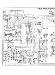
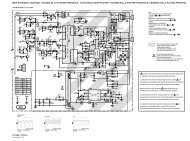
<strong>LC</strong>-<strong>20SH1E</strong>DESCRIPTION OF SCHEMATIC DIAGRAMVOLTAGE MEASUREMENT CONDITION:1. The voltages at <strong>test</strong> points are measured on thestable supply voltage of AC 220-240V. Signals arefed by a colour bar signal generator for servicingpurpose and the above voltages are measured witha 20k ohm/V <strong>test</strong>er.INDICATION OF RESISTOR & CAPACI-TOR:RESISTOR1. The unit of resistance “Ω” is omitted.(K=kΩ=1000 Ω, M=MΩ).2. All resistors are ± 5%, unless otherwise noted.(J= ± 5%, F= ± 1%, D= ± 0.5%)3. All resistors are 1/16W, unless otherwise noted.4. All resistors are Carbon type, unless otherwisenoted.C : Solid W : CementS : Oxi<strong>de</strong> Film T : SpecialN : Metal CoatingCAPACITOR1. All capacitors are µF, unless otherwise noted.(P=pF=µµF).2. All capacitors are 50V, unless otherwise noted.3. All capacitors are Ceramic type, unless otherwisenoted.(ML): Mylar (TA): Tantalum(PF): Polypro Film (ST): StyrolCAUTION:This circuit diagram is original one, therefore there may be aslight difference from yours.IMPORTANT SAFETY NOTICE:PARTS MARKED WITH “å” () AREIMPORTANT FOR MAINTAINING THE SAFETY OFTHE SET. BE SURE TO REPLACE THESE PARTSWITH SPECIFIED ONES FOR MAINTAINING THESAFETY AND PERFORMANCE OF THE SET.32