Program EDDYBL
Program EDDYBL
Program EDDYBL
You also want an ePaper? Increase the reach of your titles
YUMPU automatically turns print PDFs into web optimized ePapers that Google loves.
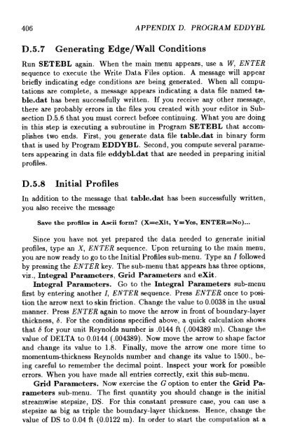
406 APPENDIX D. PROGRAM <strong>EDDYBL</strong>D.5 .7 Generating Edge/Wall ConditionsRun SETEBL again . When the main menu appears, use a W ENTERsequence to execute the Write Data Files option . A message will appearbriefly indicating edge conditions are being generated . When all computationsare complete, a message appears indicating a data file named table.dathas been successfully written . If you receive any other message,there are probably errors in the files you created with your editor in SubsectionD.5 .6 that you must correct before continuing . What you are doingin this step is executing a subroutine in <strong>Program</strong> SETEBL that accomplishestwo ends . First, you generate data file table.dat in binary formthat is used by <strong>Program</strong> <strong>EDDYBL</strong> . Second, you compute several parametersappearing in data file eddybl.dat that are needed in preparing initialprofiles .D.5.8Initial ProfilesIn addition to the message that table.dat has been successfully written,you also receive the messageSave the profiles in Ascii form? (X=eXit, Y=Yes, ENTER=No) . . .Since you have not yet prepared the data needed to generate initialprofiles, type an X, ENTER sequence . Upon returning to the main menu,you are now ready to go to the Initial Profiles sub-menu . Type an I followedby pressing the ENTER key . The sub-menu that appears has three options,viz ., Integral Parameters, Grid Parameters and eXit .Integral Parameters . Go to the Integral Parameters sub-menufirst by entering another I, ENTER sequence . Press ENTER once to positionthe arrow next to skin friction . Change the value to 0 .0038 in the usualmanner . Press ENTER again to move the arrow in front of boundary-layerthickness, 6 . For the conditions specified above, a quick calculation showsthat 6 for your unit Reynolds number is .0144 ft ( .004389 m) . Change thevalue of DELTA to 0 .0144 ( .004389) . Now move the arrow to shape factorand change its value to 1 .8 . Finally, move the arrow one more time tomomentumthickness Reynolds number and change its value to 1500 ., beingcareful to remember the decimal point. Inspect your work for possibleerrors . When you have made all entries correctly, exit this sub-menu .Grid Parameters . Now exercise the G option to enter the Grid Parameterssub-menu . The first quantity you should change is the initialstreamwise stepsize, DS . For this constant pressure case, you can use astepsize as big as triple the boundary-layer thickness . Hence, change thevalue of DS to 0.04 ft (0 .0122 m) . In order to start the computation at a


