Hitachi Inverter Rope Hoist
Hitachi Inverter Rope Hoist
Hitachi Inverter Rope Hoist

You also want an ePaper? Increase the reach of your titles
YUMPU automatically turns print PDFs into web optimized ePapers that Google loves.
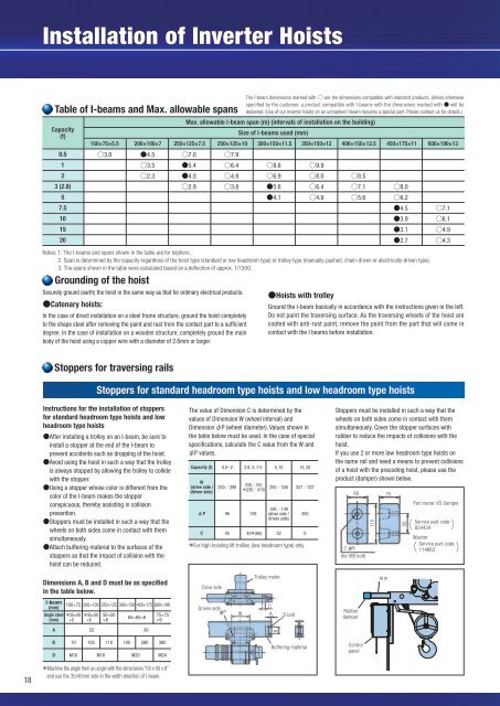
Installation of <strong>Inverter</strong> <strong>Hoist</strong>sCapacity(t)0.5123 (2.8)57.5101520The I-beam dimensions marked with are the dimensions compatible with standard products. Unless otherwisespecified by the customer, a product compatible with I-beams with the dimensions marked with will bedelivered. (Use of our inverter hoists on an unmarked I-beam requires a special part. Please contact us for details.)Max. allowable I-beam span (m) (intervals of installation on the building)Size of I-beams used (mm)150×75×5.5 200×100×7 250×125×7.5 250×125×10 300×150×11.5 350×150×12 400×150×12.5 450×175×11 600×190×133.0 4.53.52.37.05.44.02.97.96.44.93.88.66.95.64.19.98.06.44.98.57.15.68.06.24.53.93.12.77.16.14.94.3Table of I-beams and Max. allowable spansNotes: 1. The I-beams and spans shown in the table are for telphers.2. Span is determined by the capacity regardless of the hoist type (standard or low headroom type) or trolley type (manually-pushed, chain-driven or electrically-driven type).3. The spans shown in the table were calculated based on a deflection of approx. 1/1500.Grounding of the hoistSecurely ground (earth) the hoist in the same way as that for ordinary electrical products.Catenary hoists:In the case of direct installation on a steel frame structure, ground the hoist completelyto the shape steel after removing the paint and rust from the contact part to a sufficientdegree. In the case of installation on a wooden structure, completely ground the mainbody of the hoist using a copper wire with a diameter of 2.6mm or larger.Stoppers for traversing rails<strong>Hoist</strong>s with trolleyGround the I-beam basically in accordance with the instructions given in the left.Do not paint the traversing surface. As the traversing wheels of the hoist arecoated with anti-rust paint, remove the paint from the part that will come incontact with the I beams before installation.Stoppers for standard headroom type hoists and low headroom type hoistsAbout installation of stoppers for Double-RailType hoistsStoppers must be installed in such a way that thewheels of the hoist come in contact with the bothsides of the traversing rail simultaneously.The stopper height ( “a” ) must be at least onefourth of the wheel rolling diameter.Double-Rail Type hoists employ an automaticcenter adjustment structure in which the axle onthe Driven side is deviated so that the 4 wheelscontact the surface completely. For this reason,the amount of deviation varies depending on theheight difference between the right and left rails.Stoppers must be installed in such a way that theright and left wheels come in contact with themsimultaneously taking into consideration theamount of the deviation due to the rail heightdifference.The diameter of the wheel rolling contact sectionof the stopper must be “the wheel rolling diameter+ 10mm.”Capacity(t)2-57.5-10Stoppers for Double-Rail Type <strong>Hoist</strong>sWheel rolling diameter(d)160195Drive sideAxle is not deviated.Diameter of the wheel rolling contact section(D)170205StopperDriven sideDifference in the stopper installationlocation due to the axle deviation.This difference varies depending onthe height difference between the rightand left rails. (On-site adjustment ispossible.)Max. amount of deviation:5t or smaller: 10mm7.5t or larger: 15mmDiameter of the wheel rollingcontact section(D)Wheel rolling diameter(d)Traveling railStopper height(a)40 or higher49 or higher(Unit: mm)Instructions for the installation of stoppersfor standard headroom type hoists and lowheadroom type hoistsAfter installing a trolley on an I-beam, be sure toinstall a stopper at the end of the I-beam toprevent accidents such as dropping of the hoist.Avoid using the hoist in such a way that the trolleyis always stopped by allowing the trolley to collidewith the stopper.Using a stopper whose color is different from thecolor of the I-beam makes the stopperconspicuous, thereby assisting in collisionprevention.Stoppers must be installed in such a way that thewheels on both sides come in contact with themsimultaneously.Attach buffering material to the surfaces of thestoppers so that the impact of collision with thehoist can be reduced.The value of Dimension C is determined by thevalues of Dimension W (wheel interval) andDimension P (wheel diameter). Values shown inthe table below must be used. In the case of specialspecifications, calculate the C value from the W andP values.Capacity (t)W(drive side /driven side)PC0.5-2230310200290(230410)250330 32732796452.8, 3, 7.512840(90)5, 10156140(drive side /driven side)For high hoisting lift trollies (low headroom type) only.3215, 202000Stoppers must be installed in such a way that thewheels on both sides come in contact with themsimultaneously. Cover the stopper surfaces withrubber to reduce the impacts of collisions with thehoist.If you use 2 or more low headroom type hoists onthe same rail and need a means to prevent collisionsof a hoist with the preceding hoist, please use theproduct (damper) shown below.2-9(for M8 bolt)60 7011050Part name: VD Damper Service part code:854434WasherService part code:114863 15-2030250350260360In the case of a special specification hoist, make sure that “D” and “a” values that match the wheel rolling diameter ( “d” ) value are used.Weight of the hook block of the hoistThe approximate weight of the hook block of the hoist is as shown in the table below.Capacity (t)Standard Headroom TypeLow Headroom TypeDouble-Rail Type0.51010−11010−22020202.830303033030305 7.570 15070 −70 15010200−20063 or higher88 or higher15 20200 300− −200 300(Unit: kg)30−−40018Installation ofinverter hoistsDimensions A, B and D must be as specifiedin the table below.Drive sideTrolley motorArmI-beam(mm)Angle steel(mm)150×75 200×100 250×125 300×150 450×175 600×19035×50×645×50×650×50×665×65×675×75×9Driven side PWCAD boltRubberdamperA 22 30BBD70M10105 110 190 280 380M16 M20 M24Buffering materialControlpanel18Machine the angle from an angle with the dimensions “50 x 50 x 6”and use the 35/45mm side in the width direction of I-beam.19