Deck Installation - Barker Lumber Co.
Deck Installation - Barker Lumber Co.
Deck Installation - Barker Lumber Co.

You also want an ePaper? Increase the reach of your titles
YUMPU automatically turns print PDFs into web optimized ePapers that Google loves.
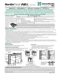
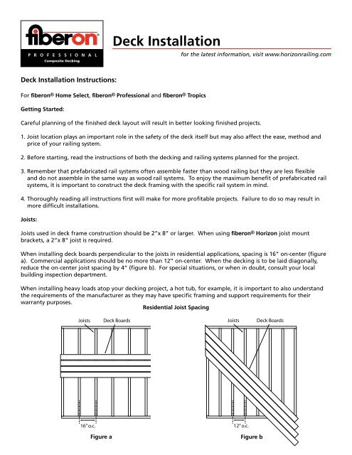
<strong>Deck</strong> <strong>Installation</strong>for the latest information, visit www.horizonrailing.com<strong>Deck</strong> <strong>Installation</strong> Instructions:For fiberon ® Home Select, fiberon ® Professional and fiberon ® TropicsGetting Started:Careful planning of the finished deck layout will result in better looking finished projects.1. Joist location plays an important role in the safety of the deck itself but may also affect the ease, method andprice of your railing system.2. Before starting, read the instructions of both the decking and railing systems planned for the project.3. Remember that prefabricated rail systems often assemble faster than wood railing but they are less flexibleand do not assemble in the same way as wood rail systems. To enjoy the maximum benefit of prefabricated railsystems, it is important to construct the deck framing with the specific rail system in mind.4. Thoroughly reading all instructions first will make for more profitable projects. Failure to do so may result inmore difficult installations.Joists:Joists used in deck frame construction should be 2”x 8” or larger. When using fiberon ® Horizon joist mountbrackets, a 2”x 8” joist is required.When installing deck boards perpendicular to the joists in residential applications, spacing is 16” on-center (figurea). <strong>Co</strong>mmercial applications should be no more than 12” on-center. When the decking is to be laid diagonally,reduce the on-center joist spacing by 4” (figure b). For special situations, or when in doubt, consult your localbuilding inspection department.When installing heavy loads atop your decking project, a hot tub, for example, it is important to also understandthe requirements of the manufacturer as they may have specific framing and support requirements for theirwarranty purposes.Residential Joist SpacingJoists<strong>Deck</strong> BoardsJoists<strong>Deck</strong> Boards16” o.c.12” o.c.Figure aFigure b
<strong>Deck</strong> <strong>Installation</strong>for the latest information, visit www.horizonrailing.comWhen installing blocking for more intricate decking patterns,remember that solid blocking (blocking laid on the flat) will inhibitwater flow and result in buildup of organic materials over time,which will make cleaning more difficult. For best results whenblocking is required, it should be installed ladder style (figure c).Board Spacing:All decking materials, whether wood, composite or metal,undergo some degree of linear expansion with the changes ofweather and the season. To compensate for the effects ofcontraction and expansion, the following installation standardsmust be maintained:BlockingStringers or JoistsBlockingFigure c• 3/16” side to side spacing between the boards (figure d).• 1/4” gap between the deck board and any solid structure such as a wall or post (figure d).• 1/8” gap between board ends (figure e).Adhering to these spacing parameters will:• Promote proper drainage and ventilation.• Aid in the removal of organic debris.• Meet the requirements of the fiberon ® warranty.Fasteners:The use of stainless steel fasteners is strongly recommended. Approved coated fasteners may also be used, buttheir performance may not be as good as stainless steel. Plain, galvanized surface fasteners are not recommended.REQUIREMENTSDo not fasten within 1-1/2” of the end of a board. It is necessary to pre-drill end of board screw holes to preventimmediate or eventual end splitting (figure f). Pre-drilling all holes, which will add time to the project, is notnecessary, but it will result in better looking finished projects.Side-To-Side Spacing End Gapping Fastener Setback1/4” Gap1/8” Gap1-1/2” Setback<strong>Deck</strong>Board #1<strong>Deck</strong>Board #1<strong>Deck</strong>Board #11“<strong>Deck</strong>Board #21“<strong>Deck</strong>Board #21“<strong>Deck</strong>Board #23/16” GapAdded JoistFigure d Figure e Figure f
<strong>Deck</strong> <strong>Installation</strong>for the latest information, visit www.horizonrailing.comFasteners (<strong>Co</strong>nt.)Fasteners should always be driven in at a 90 degree angle to the decking surface.Toe nailing/screwing is not recommended (figure g). Instead, theplacement of an additional joist, when needed, is recommended to allowperpendicular installation of fasteners(figure h).Do Not Toe-NailWRONG!Clean, perfectly straight lines of fasteners look better than wobbly lines. Use whitechalk, straight boards or string lines as templates for straight lines. DO NOT USECOLORED CHALK. <strong>Co</strong>lored chalk is designed to be permanent and will stain thedecking surface. There is no known way to remove colored chalk from decking.All brands of fiberon ® decking may be face fastened. Annual thread, ring shank andspiral shank nails, of sufficient length, have excellent holding power and producegood results. Gun nails may be used but, depending on the gun, the temperature ofthe decking and other factors such as head type, head size and shank nail geometry,guns may not produce optimal results. Test first.<strong>Deck</strong>Joist<strong>Deck</strong>Figure gScrews have superior holding power. <strong>Co</strong>nventional bugle head decking screwsproduce solid connections but have a tendency to cause mushrooming. Themushrooms may be left as is, flattened or removed (pat down with a rubber mallet),as desired.For a cleaner look, stainless steel screws with small casing or finish style headscan produce nearly invisible results. Achieving this look is possible with screwsdesigned specifically for composite decks. Available commercially, in home centersand hardware stores, these screws are engineered specifically to work withcomposite decking and prevent mushrooming, resulting in better looking finishedprojects (figure i).For the most attractive installations, approved commercially available hiddenfastener systems may be used. Always read the usage instructions of the specificfastener manufacturer thoroughly before beginning installation. It is alwaysprudent to test the particular fastener, ensuring the appearance is acceptable to theowner, as different fasteners produce different looks. Most require pre-drilling toeliminate bubbling of the surface of the dense decking material.Proper <strong>Installation</strong>22.5-dgree cut1-1/2”90-degrees<strong>Deck</strong><strong>Deck</strong>1”JoistJoistFigure hTypical <strong>Co</strong>mposite <strong>Deck</strong> ScrewsFigure i
<strong>Deck</strong> <strong>Installation</strong>for the latest information, visit www.horizonrailing.comWood Grain PatternsNote that the graining on fiberon ® Home Select and fiberon ® Professional <strong>Deck</strong>ing is directional. Different lookscan be achieved by laying the decking in the same or alternating directions (figure j).Wood Grain Orientation During installationSame DirectionAlternating DirectionFigure jThe Graining Pattern repeats approximately every three feet along the board length. To ensure you orient theboards to achieve the desired effect, a directional label is affixed to each board showing the direction of thegraining. Should this label be misplaced or discarded, you can use a key feature of the graining pattern as areference. During the planning phase of any deck project, notations about grain direction should be made toachieve the desired effect (figure k).Figure kKey feature
<strong>Deck</strong> <strong>Installation</strong>for the latest information, visit www.horizonrailing.comFastening Boardsfiberon ® Home Select <strong>Deck</strong>ing, unlike fiberon ® Professional and fiberon ® Tropics,must be face fastened with two fasteners per joist (figure l). The grained side isdesigned to be face up. fiberon ® Professional and fiberon ® Tropics <strong>Deck</strong>ing requirestwo fasteners at each end but only one fastener per joist (figure m). Designedfor the professional deck builder, this installation efficiency results in a 40%reduction in fasteners and a 30% reduction in labor. Since fiberon ® Professional<strong>Deck</strong>ing is grained identically on both sides, two usable faces are available. Thisreversibility may reduce waste by 15%. While face fastening is allowed on allfiberon ® decking products, the use of hidden fasteners is highly recommended withfiberon ® Tropics to create a smooth, unblemished, tropical hardwood surface.Scarf CutsScarf cuts (figure n) make the end gapping less visible. An angle of 22.5 degrees isrecommended. Sharper angles leave a “feather edge” that may round off over time.Remember to maintain proper end gapping.Fasciafiberon ® decking is complimented by a color matched fascia board. Available wherefiberon ® decking products are sold, the fascia board should be fully supported by asub-fascia made of lumber and fastened with 3 fasteners every 16”on-center (figure o).Fascia may also be used for risers in the construction of stairs and completes thelook. Ripped to width, fiberon ® fascia may be used to wrap posts or stringers, but itis NOT intended for structural applications.VentilationTo prevent excessive water absorption, an unobstructed air flow is required belowdeck. Flat areas where standing water may gather should be addressed by gradingor improved drainage. For decks with limited ventilation, add flow through vents atvarious locations around rim joist.Scarf CutFigure l(Typical fasteningpattern for fiberon ®Home Select<strong>Deck</strong>ing)Figure m(Typical fasteningpattern for fiberon ®Professional andfiberon ® Tropics<strong>Deck</strong>ing)Proper Fascia <strong>Installation</strong>2” x 8” Joist1-1/2”90-degrees2” x 8” Backer Board<strong>Deck</strong><strong>Deck</strong>Joist1”Joist16”FasciaFasciaFigure nFigure o
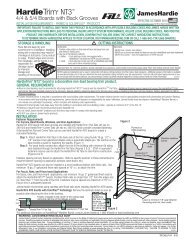
R O P I C ST R O P I C STFascia <strong>Installation</strong>For the latest installation information, visit www.fiberondecking.com.fiberon® Tropics fascia is designed for fascia applications only. It is NOT to be used as structural members, decking surfacesor stair treads. Before initiating any project, obtain a copy of your local building codes and understand them thoroughly.The following installation instructions are intended as a general guideline based on common building practices used in fasciainstallation. Local building code requirements will always supercede any and all suggested procedures and measurements inthe following installation guideline.fiberon® Tropics FasciaUse fiberon® Tropics fascia as a color matched trim accessory for fiberon® Tropics decking. It can be used as an aesthetic coveringfor exposed rim joists, stair stringers and stair risers. All fiberon® Tropics fascia boards must be fully supported by a sub-fascia (backerboard) made of structurally sound lumber and fastened with 2 fasteners every 16” on center (Figure a). Ripped to width, fiberon®Tropics fascia may be used to wrap posts or stringers (Figure b), but it is NOT intended for any structural applications.1. Install posts and joists in a manner compliant with all building codes and decking manufacturer’s recommendations.2. Cut and attach sub-fascia (nominal 2”x12” backer boards) to the ends of exposed joists using 3” galvanized screws (figure a).3. Cut fascia to length and mount top board directly to the backer board every 16” on-center using 3” galvanized screws.4. Cut second fascia board to length and mount directly under top board leaving a 3/16” gap between boards for normalexpansion/contraction.IMPORTANT NOTES:DO NOT fasten fascia within 1-1/2” of end of fascia board as it may cause eventual cracking of boards.DO NOT fasten fascia within 1” of edge of fascia board as it may cause eventual cracking of boards.To ensure a clean finish, always drive fasteners into fascia at a 90-degree angle.DO NOT butt fascia boards together when installing. Be sure to leave a 1/8” gap between boards.For longer runs, fascia may be scarf cut (figure c) for a cleaner appearance.At corners, fascia may be butt jointed (figure d) or angle cut (figure e) to create a clean appearance.Joists2 x 12 Backer BoardSuggested StringerFascia Application16”FasciaFigure a2 x 12 Backer BoardFasciaFigure bVentilationTo prevent excessive waterabsorption, an unobstructed airflow is required below deck. Flatareas where standing water maygather should be addressed bygrading or improved drainage. Fordecks with limited ventilation, addflow through vents at variouslocations around rim joist.Fascia22.5 o cut1-1/2”Backer BoardFasciaFigure c(Scarf Cut)90 oPost1”1-1/2”JoistSub-fasciaFasciaFigure d(Butt Joint)3/16” GapPost1”1-1/2”Sub-fasciaJoistFasciaFigure e(Angle Joint)3/16” GapFiber <strong>Co</strong>mposites, LLC 181 Random Drive, New London, NC 28127 704-463-7120
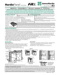
www.phantomfastener.comPhantom Hidden Fastenerby®for the latest information, visit www.horizonrailing.com<strong>Installation</strong> Instructions: Phantom Hidden FastenersThe Phantom Fastener is a hidden deck fastener system designedspecifically for fiberon ® Professional GV and fiberon ® Tropics GVdeck boards. The Phantom Fastener is the quickest way to installany deck and creates a smooth deck surface, uninterupted byscrews or nails.CAUTION: <strong>Co</strong>ntains parts with sharp edges. Use proper care.Initial installation of deck boards1. Position the first deck board on the support joists. Leave a 1/4”gap from any permanent structure (fig. 2).2. Pre-drill the first deck board with a 1/8” drill along the outsideedge of the board at every support joist. Toprevent cracking of the board the holes at the end of theboard should be a minimum of 1-1/2” from the end. The holesalong the grooved edge of the board should be a minimum of1” from the edge.3. Secure the first deck board by fastening a #10 x 2-1/4” long stainless steel deck screw in each pre-drilled hole.DO NOT OVER-TIGHTEN THE SCREWS.4. Insert a Phantom Fastener into the side channel of the board at every support joist (pronged end first).Pronged end should engage the deck board by a minimum of 5/16” (fig. 3a). Center the screw hole on the joist.5. Install a screw (provided with the fasteners) through the hole in the Phantom Fastener into the centerof each support joist. Angle the fastener toward the first deck board (fig. 3a). DO NOT OVER-TIGHTEN THESCREWS.Figure 1: Preparation* Typical residential joist spacing.12” O.C. for commercial applicationsAlways check local codes before construction.Structural Joist (added to support end-to-end seam)Structural JoistWall or other permanent structure.Figure 2: First BoardPhantom Fastener1/8”<strong>Deck</strong>Board1-1/2”Wall or other permanent structure.Figure 3: <strong>Installation</strong>ab5/16” engagementInsert pronged tabinto fixed board.Slide fastener into side channel of decking board at every support joist.Install screw provided through fastener hole into each support joist.16” O.C.*Locate next slotted board against the fastener tabs.Slightly lift the outer edge of the board and slide over fastener tabs.1/4”Structural JoistStructural JoistStructural JoistStructural Joist1”Structural JoistFastenerc3/16” gapBe sure fasteners are fully seated into each board to ensure even spacing.For more information & installation support call: (704) 463-7120
www.phantomfastener.comPhantom Hidden Fastenerby®for the latest information, visit www.horizonrailing.comInitial installation of deck boards (continued)6. Position the next deck board against the fastener tabs and slide the board onto the tabs. If necessary, slightly liftthe outer edge of the board to ease the assembly of the board onto the fastener tabs (fig. 3b). When installedproperly the fastener will ensure a 3/16” gap (fig. 3c).7. Repeat steps 4 - 6 for each deck board.8. Position the final deck board onto the last set of Phantom Fasteners. Ensuring a consistent gap between boards(fig. 4), predrill the final deck board with a 1/8” drill along the outside edge of the board at every support joist.The holes at the end of the board should be a minimum of 1-1/2” from the end. The holes along the groovededge of the board should be a minimum of 1” from the edge (fig. 5).9. Secure the final deck board by fastening a #10 x 2-1/4” long stainless steel deck screw in each pre-drilled hole. DONOT OVER-TIGHTEN THE SCREWS<strong>Deck</strong> Board ReplacementFigure 4: Maintain GappingFigure 5: Last Board1. Make two parallel cuts down thecenter of the board to be replaced.Remove the center section fromthe board (fig.6).2. Remove the remaining two piecesfrom the tabs of the correspondinghidden fasteners.<strong>Deck</strong>Board3/16”1/8”Wall or other permanent structure.1-1/2”1/8”<strong>Deck</strong>Boardscrap board3/16”Wall or other permanent structure.3. With a reciprocating saw, removethe tabs on the fasteners whichhave the screw showing (fig. 6a).Structural Joist1”Structural Joist4. Position the new deck board ontothe remaining tabs (fig. 7).5. Ensuring a consistent 3/16” gapbetween boards, predrill a 1/8”hole along the unfastened edge atevery support joist.Figure 6: Removing BoardRemove centercut outFigure 7: Replacing BoardCut HereFigure 6aTrim tabs fromfasteners withexposed screwsonly.1/8”6. Secure the board by fastening a#10 x 2-1/4” long stainless steeldeck screw in each pre-drilled hole.Cut HereEngagefastenertabs intoside deckchannel3/16”New BoardRemove sidepiecesFor more information & installation support call: (704) 463-7120
Fiber <strong>Co</strong>mposites, LLC 181 Random Drive, New London, NC 28127 • 704-463-7120 • www.fibercomposites.comfiberon® Professional <strong>Deck</strong> <strong>Installation</strong>fiberFAQ’sRelease Date06/23/05Effective DateImmediatelyBulletinD062305Fastening end-to-end seams (butt joints) requires special attention.Boards may not be fastened within 1-1/2 inches of board end.When installing any composite deck boards manufactured by Fiber <strong>Co</strong>mposites, installer mustadhere to the following procedures to ensure a proper installation:(1) Attach a nailing board (nailer) alongside of the supportjoist.(2) Fasten the first board (<strong>Deck</strong> Board #1) to joist(3) Fasten the second board (<strong>Deck</strong> Board #2) to the nailboard (nailer).(4) Repeat pattern across the installation.Failure to follow to thisprocedure will result inimmediate or eventual splittingat the ends of the <strong>Deck</strong> Boards.Improper installation is notcovered by theProduct Warranty.Important SpecificationsRecommended spacing between boards(side-to-side) to allow for efficient removal of waterand organic debris................................................... 3/16”Spacing between boards (end-to-end).................... 1/8”Maximum distance between floor joists/stringers... 16” O.C.Minimum fastener set back from end of board....... 1.5” Min.Spacing between board and solid structure............ 1/4”ALWAYS:ALWAYS:Pre-drill all fastener holes at board ends prior toinstallation with a 1/8” counter sink drill bit.Drive fastener perpendicular to deck surface(not at an angle) into board until top of screwhead is flush with deck surface.NEVER:OVER TIGHTEN SCREWS! Over tightening willinduce cracking at board ends.1-1/2” SetbackALWAYS:Use fasteners designed for composite decking.This will reduce mushrooming.<strong>Deck</strong>Board #1<strong>Deck</strong>Board #2Nailing BoardDrawing for Illustrative purposes only.Drawing not to scale.