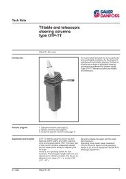
Sauer-Danfoss series OTP steering columns
Sauer-Danfoss series OTP steering columns
Sauer-Danfoss series OTP steering columns
- No tags were found...

Create successful ePaper yourself
Turn your PDF publications into a flip-book with our unique Google optimized e-Paper software.
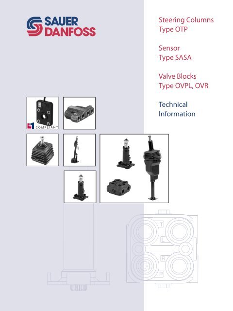
Steering ColumnsType <strong>OTP</strong>SensorType SASAValve BlocksType OVPL, OVRTechnicalInformation
<strong>OTP</strong> Steering Columns / OVPL, OVR Valve BlocksTechnical InformationContentsA Wide Range of SteeringComponentsA wide range of <strong>steering</strong> components................................................................................................... 4Technical LiteratureSurveyTechnical literatur survey............................................................................................................................. 6Fixed Steering Columns,<strong>OTP</strong>B and <strong>OTP</strong>MVersions.............................................................................................................................................................. 7Steering wheel connections: SWC...................................................................................................... 7Body tubes.................................................................................................................................................10Flanges........................................................................................................................................................12Axle journals..............................................................................................................................................15Surface protection..................................................................................................................................16Horn buttons.............................................................................................................................................16Wire ends for <strong>steering</strong> wheel horn button.....................................................................................18Flasher activator.......................................................................................................................................18Steering wheel sensors.........................................................................................................................19Code numbers and weights, <strong>OTP</strong>B.........................................................................................................20Code numbers and weights, <strong>OTP</strong>M .......................................................................................................22Specification table for non-catalogue numbers of <strong>OTP</strong> fixed <strong>steering</strong> <strong>columns</strong> ..................23Dimensions.....................................................................................................................................................24Installation.......................................................................................................................................................26Load on fixed <strong>steering</strong> <strong>columns</strong>.........................................................................................................30Axle journals for customer made <strong>columns</strong>...................................................................................31Horn button...............................................................................................................................................32Adjustable SteeringColumns, <strong>OTP</strong>Versions............................................................................................................................................................33<strong>OTP</strong>-ST, standard tilting <strong>steering</strong> <strong>columns</strong>.....................................................................................35<strong>OTP</strong>-MT, mini tilting <strong>steering</strong> <strong>columns</strong>............................................................................................36<strong>OTP</strong>-STT, standard tilt and telescopic <strong>steering</strong> <strong>columns</strong>...........................................................38<strong>OTP</strong>-BTT, bottom tilt and telescope <strong>steering</strong> <strong>columns</strong>..............................................................39Specification table of <strong>Sauer</strong>-<strong>Danfoss</strong> adjustable <strong>steering</strong> <strong>columns</strong> ..........................................40Load on adjustable <strong>steering</strong> <strong>columns</strong>...................................................................................................41Installation of adjustable <strong>steering</strong> <strong>columns</strong>........................................................................................41Installation of <strong>OTP</strong>-MT and <strong>OTP</strong>-BTT.....................................................................................................42Sensor SASASensor AdapterKit, SAKGeneral Information....................................................................................................................................43Versions, code numbers and weights....................................................................................................43CAN message protocol...............................................................................................................................44Parameter setup............................................................................................................................................45© 2008 <strong>Sauer</strong>-<strong>Danfoss</strong>. All rights reserved.2 11015554 • Rev AB • May 2008<strong>Sauer</strong>-<strong>Danfoss</strong> accepts no responsibility for possible errors in catalogs, brochures and other printed material.<strong>Sauer</strong>-<strong>Danfoss</strong> reserves the right to alter its products without prior notice. This also applies to productsalready ordered provided that such alterations aren’t in conflict with agreed specifications. All trademarks inthis material are properties of their respective owners. <strong>Sauer</strong>-<strong>Danfoss</strong> and the <strong>Sauer</strong>-<strong>Danfoss</strong> logotype aretrademarks of the <strong>Sauer</strong>-<strong>Danfoss</strong> Group.Front cover illustrations: F300626, F300628, F300629, F300019, F300633, F300634, F300734, F300738. Drawing: 150-674.eps
<strong>OTP</strong> Steering Columns / OVPL, OVR Valve BlocksTechnical InformationContentsSensor SASASensor AdapterKit, SAK(continued)Technical data................................................................................................................................................46Dimensions.....................................................................................................................................................47Installation.......................................................................................................................................................48Valve Block OVPLAngle Block OVRVersions............................................................................................................................................................50Code numbers and weights......................................................................................................................50Technical data................................................................................................................................................54Installation.......................................................................................................................................................56Dimensions.....................................................................................................................................................57Version..............................................................................................................................................................59Code numberand weight...........................................................................................................................59Installation:......................................................................................................................................................59Dimensions.....................................................................................................................................................6011015554 • Rev AB • May 20083
<strong>OTP</strong> Steering Columns / OVPL, OVR Valve BlocksTechnical InformationA Wide Range of Steering ComponentsA Wide Range ofSteering ComponentsF300599<strong>Sauer</strong>-<strong>Danfoss</strong> is the largest producer in the world of <strong>steering</strong> components forhydrostatic <strong>steering</strong> systems on off-road vehicles. <strong>Sauer</strong>-<strong>Danfoss</strong> offers <strong>steering</strong> solutionson both component and system level. Our product range makes it possible to coverapplications of all types - ranging from ordinary 2-wheel <strong>steering</strong> (also known asAckermann <strong>steering</strong>) to articulated <strong>steering</strong>, complicated 4-wheel <strong>steering</strong>, automatic<strong>steering</strong> (e.g. by sensor) and remote controlled <strong>steering</strong> via satellite.We can offer more than 1000 different <strong>steering</strong> units, 150 different priority valves and300 different <strong>steering</strong> <strong>columns</strong> categorized in types, variants and sizes.For hydrostatic <strong>steering</strong> systems <strong>Sauer</strong>-<strong>Danfoss</strong> offers:· Mini <strong>steering</strong> units with displacements from 32 to 100 cm 3 [1.95 to 6.10 in 3 /rev] perrevolution, flow up to 20 l/min [5.28 US gal/min], <strong>steering</strong> pressure up to 125 bar[1813 psi].· Steering units with displacements from 40 to 1200 cm 3 [2.44 to 73.23 in 3 ] perrevolution, flow up to 100 l/min [26.42 US gal/min], <strong>steering</strong> pressure up to 210 bar[3045 psi].· Priority valves for rated flows of 40, 80, 120 and 160 l/min [10.57, 21.13, 31.70 and42.27 US gal/min] pressure up to 350 bar [5076 psi].· Flow amplifiers with amplification factors of 4, 5, 8, 10 or 20 for rated oil flows of 240and 400 l/min [63.4 and 106 US gal/min], <strong>steering</strong> pressure up to 210 bar [3045 psi].· Pilot operated <strong>steering</strong> valves with <strong>steering</strong> flows up to 100 l/min [26.4 US gal/min],<strong>steering</strong> pressure up to 250 bar [3625 psi].For electro-hydraulic <strong>steering</strong> systems <strong>Sauer</strong>-<strong>Danfoss</strong> offers:· Pilot operated <strong>steering</strong> valves (pilot operated by hydrostatic <strong>steering</strong> unit or byelectrical signal) with <strong>steering</strong> flows up to 100 l/min [26.4 US gal/min], <strong>steering</strong>pressure up to 250 bar [3625 psi].4 11015554 • Rev AB • May 2008
<strong>OTP</strong> Steering Columns / OVPL, OVR Valve BlocksTechnical InformationA Wide Range of Steering ComponentsA Wide Range of SteeringComponents(continued)For the <strong>steering</strong> units <strong>Sauer</strong>-<strong>Danfoss</strong> offers:• Steering <strong>columns</strong>: fixed, tiltable and/or telescopic with or without horn switch andsensor for start/stop of pump, in lengths from 45 to 1200 mm [1.77 to 47.24 in]Characteristic features of <strong>steering</strong> units:• Low <strong>steering</strong> torque: From 0.5 N•m to 3 N•m [4.42 to 26.6 lbf•in] in normal <strong>steering</strong>situations• Low noise level• Low pressure drop• Many types available: Open center None reaction, Open center Reaction, Closedcenter None reaction, Load Sensing, Load Sensing Reaction• One or more built-in valve functions: relief valve, shock valves, suction valves, nonereturn valve in P-line and in LS-line• Optional port connections (according to ISO, SAE or DIN standards)Characteristic features of electro-hydraulic <strong>steering</strong> system:• High <strong>steering</strong> pressure requiring smaller cylinders and flow• Low pilot pressure and flow ensuring extremely low noise in the cabin• The possibility of manual <strong>steering</strong> even of very heavy vehicles• Minimization of side acceleration with articulated <strong>steering</strong>• Electro-hydraulic <strong>steering</strong> valve EHPS can be combined with <strong>Sauer</strong>-<strong>Danfoss</strong> PVG 32proportional valveConcersion Factors1 N•m = [8.851 lbf•in] 1 cm 3 = [0.061 in 3 ]1 N = [0.2248 lbf] 1 l = [0.264 US gal]1 bar = [14.50 psi] °F = [1.8 °C + 32]1 mm = [0.0394 in]11015554 • Rev AB • May 20085
<strong>OTP</strong> Steering Columns / OVPL, OVR Valve BlocksTechnical InformationContens and Technical Literature SurveySurvey of Literaturewith Technical Data on<strong>Sauer</strong>-<strong>Danfoss</strong> SteeringComponentsDetailed data on all <strong>Sauer</strong>-<strong>Danfoss</strong> <strong>steering</strong> components and accessories can be found inour <strong>steering</strong> component catalogues, which are divided into 6 individual sub-catalogues:• General informationSteering components• Technical data on mini <strong>steering</strong> units and<strong>steering</strong> <strong>columns</strong> for mini <strong>steering</strong> units• Technical data on open center, andclosed center <strong>steering</strong> units• Technical data on load sensing <strong>steering</strong> units,priority valves and flow amplifiers• Technical data on hydraulic and electrohydraulicpilot operated <strong>steering</strong> valves,electrical actuation modules and appropriate<strong>steering</strong> units• Technical data on <strong>steering</strong> <strong>columns</strong> and valveblocksOSPM and <strong>OTP</strong>MOSPB, OSPC, OSPR, and OSPDOSPB, OSPC, OSPF, OSPD, OSPQ,OSPL, OSPBX, OSPLX, OLS and OSQEHPS, PVES for EHPS and OSPCX<strong>OTP</strong>, SASA, OVPL and OVRThe most important data on all <strong>Sauer</strong>-<strong>Danfoss</strong> <strong>steering</strong> components are highlighted in ageneral survey brochure.For technical information on individual variants, please contact the <strong>Sauer</strong>-<strong>Danfoss</strong> SalesOrganization.6 11015554 • Rev AB • May 2008
<strong>OTP</strong> Steering Columns / OVPL, OVR Valve BlocksTechnical InformationFixed Steering Columns, <strong>OTP</strong>Fixed Steering Columns,<strong>OTP</strong>BThe <strong>OTP</strong>B <strong>steering</strong> <strong>columns</strong> fit OSPB,OSPC, OSPD, OSPF, OSPL, OSPQ <strong>steering</strong>units and TAD torque amplifiers.Fixed Steering Columns,<strong>OTP</strong>MThe <strong>OTP</strong>M <strong>steering</strong> <strong>columns</strong> fit OSPM<strong>steering</strong> unitsVersionsSteering wheel connections: SWCThe <strong>OTP</strong>B <strong>steering</strong> <strong>columns</strong> are available with six different standard <strong>steering</strong> wheelconnections:1. A: 5 x 6,5 DIN 6888d min = 23,16 mm [0.912 in]K: Taper 1:202. B: 5 x 7,5 DIN 6888d min = 20,50 mm [0.807 in]K: Taper 1:203. D: 3 /16 x 3/8 SAE J502d min = 20,0 mm [0.787 in]L: Taper 1:16D11015554 • Rev AB • May 20087
<strong>OTP</strong> Steering Columns / OVPL, OVR Valve BlocksTechnical InformationFixed Steering Columns, <strong>OTP</strong>Versions (continued)4. With 13 /16 in-36 serrationd min = 20,97 mm [0.826 in]L: Taper 1:16N: 36 teeth5. With 7/8 in-36 serrationd min = 21,55 mm [0.848 in]M: Taper 1:19,26N: 36 teeth6. With 7/8 in-36 serrationd min = 21,80 mm [0.858 in]M: Taper 1:19,26N: 36 teeth8 11015554 • Rev AB • May 2008
<strong>OTP</strong> Steering Columns / OVPL, OVR Valve BlocksTechnical InformationFixed Steering Columns, <strong>OTP</strong>Versions (continued)The <strong>OTP</strong>M <strong>steering</strong> <strong>columns</strong> are available with three different standard <strong>steering</strong> wheelconnections.M1A: 5 • 6.5 DIN 6888d min = 16.47 mm [0.648 in]K: Taper 1:20M2(same as “5” page 8)With 7 /8 in-36 serrationd min = 21,55 mm [0.848 in]K: Taper 1:19,26M3With 11 /16 in-40 serrationd min = 17.89 mm [0.704 in]K: Taper 1:1211015554 • Rev AB • May 20089
<strong>OTP</strong> Steering Columns / OVPL, OVR Valve BlocksTechnical InformationFixed Steering Columns, <strong>OTP</strong>Versions (continued)Body tubesThe <strong>OTP</strong>B <strong>steering</strong> <strong>columns</strong> are available with three different body tube dimensions:1. Standard: Ø 38 • 1.5 mm [1.50 • 0.06 in]2. Ø38 • 2.5 mm [1.50 • 0.1in]3. Ø45 • 2.5 mm [1.77 • 0.1 in]If the <strong>steering</strong> column is longer than 150 mm [5.91 in] and support is not possible, therecommended body tube is Ø38 x 2.5mm [1.50 • 0.1in] or Ø45 x 2.5mm [1.77 • 0.1 in].10 11015554 • Rev AB • May 2008
<strong>OTP</strong> Steering Columns / OVPL, OVR Valve BlocksTechnical InformationFixed Steering Columns, <strong>OTP</strong>Versions (continued)Body tubesThe <strong>OTP</strong>M <strong>steering</strong> <strong>columns</strong> are available with one body tube dimensions:1. Standard: Ø 38 • 1.5 mm [1.50 • 0.06 in]11015554 • Rev AB • May 200811
<strong>OTP</strong> Steering Columns / OVPL, OVR Valve BlocksTechnical InformationFixed Steering Columns, <strong>OTP</strong>Versions (continued)FlangesOur <strong>OTP</strong>B <strong>steering</strong> <strong>columns</strong> are available with three different flanges:Flange AFlange B12 11015554 • Rev AB • May 2008
<strong>OTP</strong> Steering Columns / OVPL, OVR Valve BlocksTechnical InformationFixed Steering Columns, <strong>OTP</strong>Versions (continued)FlangesThe <strong>OTP</strong>M <strong>steering</strong> <strong>columns</strong> are available with one flange:Flange M14 11015554 • Rev AB • May 2008
<strong>OTP</strong> Steering Columns / OVPL, OVR Valve BlocksTechnical InformationFixed Steering Columns, <strong>OTP</strong>Versions (continued)Axle journals<strong>OTP</strong>B are available with three different axle journalsfor connection to the <strong>steering</strong> unit:1. Standard axle journal with straightsplines.In case of inadequate parallelismbetween the <strong>steering</strong> column’smounting plane (flange) and the<strong>steering</strong> unit’s <strong>steering</strong> column plane,use a spherical axle journal.For standard splines, the requiredparallelism is better than 0.5 mm inrelation to the <strong>steering</strong> unit’s <strong>steering</strong>column plane.2. Axle journal with straight splines andO-ring for noise reduction3. Spherical axle journal. This axle journalenables angular movements up to 10°between <strong>steering</strong> unit and <strong>steering</strong>column4. <strong>OTP</strong>M are available with one type ofaxle journal type “M”11015554 • Rev AB • May 200815
<strong>OTP</strong> Steering Columns / OVPL, OVR Valve BlocksTechnical InformationFixed Steering Columns, <strong>OTP</strong>Versions (continued)Surface protection<strong>OTP</strong> <strong>steering</strong> <strong>columns</strong> are available with two different kinds of surface protection:- Standard: yellow chromate- Black chromateHorn buttonsOur <strong>steering</strong> <strong>columns</strong> can be delivered with single ore double horn button (ref. below).description of horn buttons)1. Standard single horn buttonFor Ø38 mm [1.5 in] body tube, spareparts bag code number 150-52152. Standard single horn buttonFor Ø45 mm [1.77 in]body tube, spareparts bag code number150-403216 11015554 • Rev AB • May 2008
<strong>OTP</strong> Steering Columns / OVPL, OVR Valve BlocksTechnical InformationFixed Steering Columns, <strong>OTP</strong>Versions (continued)3. Flat horn buttonFor Ø38 mm [1.5 in] and Ø45 mm [1.77in] body tubes, spare parts bag codenumber 150-6762.Height: 10 mm [0.39 in] from surfaceof body tube.Due to the shape of the connectinghole in the <strong>steering</strong> column, theflat horn button cannot be directlyinterchanged with a standard hornbutton.A: Spade connector DIN 46244-A6,3-0,8 BZ4. Double horn button.Only for Ø38 mm [1.5 in] body tube,spare parts bag code number150-6288A: Covered male blade terminalsAMP 3-520107-211015554 • Rev AB • May 200817
<strong>OTP</strong> Steering Columns / OVPL, OVR Valve BlocksTechnical InformationFixed Steering Columns, <strong>OTP</strong>Versions (continued)Wire ends for <strong>steering</strong> wheel horn buttonSteering <strong>columns</strong> with horn buttons are available with various wire ends in the <strong>steering</strong>wheel end of the column:1. Standard: 100 mm wire with tin-plated end2. 100 mm wire without tin-plated end3. 100 mm wire with round AMP male connection, AMP no.1602144. 100 mm wire with flat AMP female connection, fully insulated, AMP no. 735160-05. Customer definedFlasher activator<strong>OTP</strong> <strong>steering</strong> <strong>columns</strong> with body tube Ø45 mm are available with flasher activator. Theactivator returns the flasher switch into neutral after completion of <strong>steering</strong> rotation.It is not possible to equip one and the same <strong>OTP</strong> <strong>steering</strong> column with both flasheractivator and <strong>steering</strong> wheel sensor.18 11015554 • Rev AB • May 2008
<strong>OTP</strong> Steering Columns / OVPL, OVR Valve BlocksTechnical InformationFixed Steering Columns, <strong>OTP</strong>BVersions (continued)Steering wheel sensorsOur <strong>OTP</strong> <strong>steering</strong> <strong>columns</strong> are available in versions prepared for the installation of a<strong>steering</strong> wheel sensor for pump control. We can offer two different sensors:1. ON/OFF sensorON/OFF signalData:Principle: Hall-effect, contactless, free of service.Power supply: 24 or 48 V DC ± 25%.Failure polarity protected.Output: ON/OFF, open collector, NPN outputs.Short circuit-protected.Max load on signal: 50 mAResponse time: < 100 msEnclosure: IP 54Wires: White = 24 or 48 V, Green = ON/OFF signal, Brown= 0 VLED:For service, light is on when signal is active.2. Proportional sensorData:Proportional signalPrinciple: Hall-effect, contactless, free of service.Power supply: 18-80 V DC ± 10%. Failurepolarity protected.Output: Analogue output(short circuit protected),Min load on proportional signal: 1 mAMax load on proportional signal: 10 mAResponse time: < 100 msEnclosure: IP 54Wires: White = 18-80 V, Green= proportional signal, Brown= 0 VLED:For service, light is on when signal is active.Steering wheel sensors are only available for body tube dimension Ø38 mm.Sensors can only be mounted near to the top of the column, see dimensions.ON/OFF and proportional sensors have same dimensions, see below.Steering column sensor, dimensionsHeight: Max. 12 mm [0.47 in] from surface of body tube.A: Max tightening torque: 0,5 N•mB: Wire length: As requiredConnector on wire end:• Standard: • contact pins: AMP no.: 926887-1 • housing for contact pins: AMP no.: 350779-1• Other connectors: contact <strong>Sauer</strong>-<strong>Danfoss</strong> Sales Organisation.11015554 • Rev AB • May 200819
<strong>OTP</strong> Steering Columns / OVPL, OVR Valve BlocksTechnical InformationFixed Steering Columns, <strong>OTP</strong>Code Numbers andWeights, <strong>OTP</strong>BThe following <strong>steering</strong> <strong>columns</strong> have Ø38 • 1.5 mm [1.5 • 1.06 in] body tube, B-flange,and yellow chromate coating.Fixed <strong>steering</strong> <strong>columns</strong> without horn buttonCode numberType <strong>OTP</strong>B 75 <strong>OTP</strong>B 100 <strong>OTP</strong>B 150 <strong>OTP</strong>B 200 <strong>OTP</strong>B 250 <strong>OTP</strong>B 300Length of external tube (C) mm [in] 62.7 [2.47] 100 [3.94] 154 [6.06] 200 [7.87] 250 [9.84] 300 [11.81]Weight kg [lb] 0.9 [1.98] 1.1 [2.43] 1.3 [2.87] 1.4 [3.09] 1.5 [3.31] 1.6 [3.53]1* With woodruff key 5 • 6.5 mm [.197 • .256 in]D min = 23.16 mm [0.912 in], taper 1 : 202* With woodruff key 5 • 7.5 mm [.197 • .295 in]D min = 20.50 mm [0.807 in], taper 1 : 203* With woodruff key 3 /16 • 3 /8D min = 20.00 mm [0.787 in], taper 1 : 164* With serration 13 /16 - 36D min = 20.97 mm [0.826 in], taper 1 : 165* With serration 7 /8 - 36D min = 21.55 mm [0.848 in], taper 1 : 19.266* With serration 7 /8 - 36D min = 21.80 mm [0.858 in], taper 1 : 19.26150-5031 150-5032150-5034 150-5035**150-5065 **150-5066150-5037 150-5038150-5040 150-5077 150-5041150-5043 150Z1001 150-5044 150Z1002 150Z1003 150Z1004* The numbers refer to the dimensional sketch, page 7 - 8** These code numbers have black chromate as surface protection.Fixed <strong>steering</strong> <strong>columns</strong> without horn button, continuedCode numberType <strong>OTP</strong>B 350 <strong>OTP</strong>B 400 <strong>OTP</strong>B 450 <strong>OTP</strong>B 550 <strong>OTP</strong>B 650 <strong>OTP</strong>B 750Length of external tube (C) mm [in] 350 [13.78] 400 [15.75] 450 [17.72] 550 [21.65] 650 [25.59] 763 [30.02]Weight kg [lb] 1.8 [3.97] 1.9 [4.19] 2.0 [4.41] 2.2 [4.85] 2.5 [5.51] 2.7 [5.95]1* With woodruff key 5 • 6.5 mm [.197 • .256 in]D min = 23.16 mm [0.912 in], taper 1 : 202* With woodruff key 5 • 7.5 mm [.197 • .295 in]D min = 20.50 mm [0.807 in], taper 1 : 203* With woodruff key 3 /16 • 3 /8D min = 20.00 mm [0.787 in], taper 1 : 164* With serration 13 /16 - 36D min = 20.97 mm [0.826 in], taper 1 : 165* With serration 7 /8 - 36D min = 21.55 mm [0.848 in], taper 1 : 19.266* With serration 7 /8 - 36D min = 21.80 mm [0.858 in], taper 1 : 19.26150-5033150-5036**150-5089150-5039150-5042150Z1005 150Z1006 150Z1007 150Z1008 150Z1009 150-5045* The numbers refer to the dimensional sketch, page 7 - 8** These code numbers have black chromate as surface protection.If you need other lengths, body tube dimensions, surface protection, flasher activator, flanges, noise damping or<strong>steering</strong> wheel sensor, please fill in the form on page 23 and contact the <strong>Sauer</strong>-<strong>Danfoss</strong> Sales Organization.20 11015554 • Rev AB • May 2008
<strong>OTP</strong> Steering Columns / OVPL, OVR Valve BlocksTechnical InformationFixed Steering Columns, <strong>OTP</strong>Code Numbersand Weights, <strong>OTP</strong>B(continued)Following <strong>steering</strong> <strong>columns</strong> are with Ø38 x 1,5 mm body tube, B-Flange, yellowchromate, with single standard horn button, and with standard tin-plated wire end.Fixed <strong>steering</strong> <strong>columns</strong> with single horn buttonCode numberType <strong>OTP</strong>B 75 <strong>OTP</strong>B 100 <strong>OTP</strong>B 150 <strong>OTP</strong>B 200 <strong>OTP</strong>B 250 <strong>OTP</strong>B 300Length of external tube (C) mm [in] 62.7 [2.47] 100 [3.94] 154 [6.06] 200 [7.87] 250 [9.84] 300 [11.81]Weight kg [lb] 1.0 [2.20] 1.2 [2.65] 1.4 [3.09] 1.5 [3.31] 1.6 [3.53] 1.7 [3.75]1* With woodruff key 5 • 6.5 mm [.197 • .256 in]D min = 23.16 mm [0.912 in], taper 1 : 20150-5046 150-50472* With woodruff key 5 • 7.5 mm [.197 • .295 in]D min = 20.50 mm [0.807 in], taper 1 : 20150-5049 150-50504* With serration 13 /16 - 36D min = 20.97 mm [0.826 in], taper 1 : 16150-5052 150-50535* With serration 7 /8 - 36D min = 21.55 mm [0.848 in], taper 1 : 19.26150-5055 150-50566* With serration 7 /8 - 36D min = 21.80 mm [0.858 in], taper 1 : 19.26150-5058 150Z1010 150-5059 150Z1011 150Z1012 150Z1013* The numbers refer to the dimensional sketch, page 7 - 8Fixed <strong>steering</strong> <strong>columns</strong> with single horn button, continuedCode numberType <strong>OTP</strong>B 350 <strong>OTP</strong>B 400 <strong>OTP</strong>B 450 <strong>OTP</strong>B 550 <strong>OTP</strong>B 650 <strong>OTP</strong>B 750Length of external tube (C) mm [in] 350 [13.78] 400 [15.75] 450 [17.72] 550 [21.65] 650 [25.59] 763 [30.02]Weight kg [lb] 1.9 [4.19] 2.0 [4.41] 2.1 [4.63] 2.3 [5.07] 2.6 [5.73] 2.8 [6.17]1* With woodruff key 5 • 6.5 mm [.197 • .256 in]D min = 23.16 mm [0.912 in], taper 1 : 20150-50482* With woodruff key 5 • 7.5 mm [.197 • .295 in]D min = 20.50 mm [0.807 in], taper 1 : 20150-50514* With serration 13 /16 - 36D min = 20.97 mm [0.826 in], taper 1 : 16150-50545* With serration 7 /8 - 36D min = 21.55 mm [0.848 in], taper 1 : 19.26150-50576* With serration 7 /8 - 36D min = 21.80 mm [0.858 in], taper 1 : 19.26150Z1014 150Z1015 150Z1016 150Z1017 150Z1018 150-5060* The numbers refer to the dimensional sketch, page 7 - 8If you need other lengths, body tube dimensions, surface protection, flasher activator, flanges, noise damping, typesof horn button, or <strong>steering</strong> wheel sensor, please fill in the form on page 23 and contact the <strong>Sauer</strong>-<strong>Danfoss</strong> SalesOrganization.11015554 • Rev AB • May 200821
<strong>OTP</strong> Steering Columns / OVPL, OVR Valve BlocksTechnical InformationFixed Steering Columns, <strong>OTP</strong>Code Numbers andWeights, <strong>OTP</strong>MFollowing <strong>steering</strong> <strong>columns</strong> are with Ø38 x 1,5 mm [1.496 • 0.059] body tube, M-Flange,and black chromate coating.Code numberType <strong>OTP</strong>M 163 <strong>OTP</strong>M 350Length of external tube (C) mm [in] 163 [6.42] 350 [13.78]Weight kg [lb] 1.3 [2.90] 1.8 [4.00]M 1*) With woodruff key 5 • 6.5 mm [.197 • .256 in]D min = 16.47 mm [0.648 in], taper 1 : 20M2*) With serration 7 /8 - 36D min = 21.55 mm [0.848 in], taper 1 : 19.26M6*) With serration 11 /16- 40D min = 17.89 mm [0.704 in], taper 1 : 19.26* The numbers refer to the dimensional sketch, page 9150L1024150L1026150L1028150L1025150L1027150L102922 11015554 • Rev AB • May 2008
<strong>OTP</strong> Steering Columns / OVPL, OVR Valve BlocksTechnical InformationFixed Steering Columns, <strong>OTP</strong>BSpecification Table forNon-Catalogue Numbersof Suaer-<strong>Danfoss</strong> <strong>OTP</strong>BFixed Steering ColumnsFill in your company data. Tick off and give in valuesin the table where appropriate, and send to yourlocal <strong>Sauer</strong>-<strong>Danfoss</strong> Sales OrganizationT is linked to <strong>steering</strong> wheel connection typeYour companyName Vehicle Potential, pcs/year Completed by DateFor <strong>steering</strong> unit type<strong>OTP</strong>B for: OSPB , OSPC, OSPD, OSPF, OSPL OSPQ and TAD<strong>OTP</strong>M for: OSPMSteering wheel connectionsee page 7 - 9Body tubeFlange typeC-dimensionS-dimensionAxle journalType 1 Type 2 Type 3 Type 4 Type 5 Type 6 Type M1 Type M2 Type M3 Customer definedØ38 • 1.5 mm, standard Ø38 • 2.5 mm Ø45 • 2.5 mmType A Type B Tilting Type M Customer definedMin. 45 mm, state lengthmmType A standard 10.5 mm Type B standard 6.5 mm Type M: standard -14 mm Other: State lengthmmStandard, straigth splines With O-ring Spherical Standard MSurface protectionYellow chromate (not for <strong>OTP</strong>M)Black chromateHorn buttonNoneStandard forØ38mm body tubeStandard forØ45 mm body tubeFlat versionDouble for Ø38 mm bodytube onlyHorn button: Wire lengthStandard 100 mmCustomer defined, state lengthat <strong>steering</strong> wheelmmHorn button: Wire connection<strong>steering</strong> wheelStandard, tinplatedwire endWire endwithout tin-platingRound male AMPFlat female AMPinsulatedCustomer definedFlasher activatorPrepared for <strong>steering</strong>wheel sensorSteering wheel sensorNoNoYes (for Ø45 mm body tube only)Yes (for Ø38 mm body tube only)None ON/OFF Proportional Power supply, state voltageVAlternativ specify by stating code number of basic <strong>steering</strong> column:Requested modifications:11015554 • Rev AB • May 200823
<strong>OTP</strong> Steering Columns / OVPL, OVR Valve BlocksTechnical InformationFixed Steering Columns, <strong>OTP</strong>Dimensions<strong>OTP</strong>B standard <strong>steering</strong> column referring to code numbers page 20 - 21.T-dimension is linked to SWC,Steering Wheel Connection, seepage 7 - 8CTypemm[in]<strong>OTP</strong>B 75 62.7 [2.47]<strong>OTP</strong>B 100 100 [3.94]<strong>OTP</strong>B 150 153.9 [6.06]<strong>OTP</strong>B 200 200 [7.87]<strong>OTP</strong>B 250 250 [9.84]<strong>OTP</strong>B 300 300 [11.81]<strong>OTP</strong>B 350 350 [13.78]<strong>OTP</strong>B 400 400 [15.75]<strong>OTP</strong>B 450 450 [17.72]<strong>OTP</strong>B 550 550 [21.65]<strong>OTP</strong>B 650 650 [25.59]<strong>OTP</strong>B 750 762.5 [30.02]24 11015554 • Rev AB • May 2008
<strong>OTP</strong> Steering Columns / OVPL, OVR Valve BlocksTechnical InformationFixed Steering Columns, <strong>OTP</strong>Dimensions<strong>OTP</strong>M standard <strong>steering</strong> column referring to code numbers page 22.T-dimension is linked to SWC,Steering Wheel Connection, seepage 9.CTypemm[in]<strong>OTP</strong>M 163 163 [6.42]<strong>OTP</strong>M 350 350 [13.78]11015554 • Rev AB • May 200825
<strong>OTP</strong> Steering Columns / OVPL, OVR Valve BlocksTechnical InformationFixed Steering Columns, <strong>OTP</strong>InstallationInstallation of <strong>steering</strong> column with A-flange<strong>Sauer</strong>-<strong>Danfoss</strong> <strong>steering</strong> column with A-flange can be mounted on the cabin floor, andthe <strong>Sauer</strong>-<strong>Danfoss</strong> <strong>steering</strong> unit can be mounted under the cabin floor. The S-dimensionhas to be equal to the thickness of the cabin floor + 6.5 mm [0.26 in]. Example: If thecabin floor is 4 mm [0.16in], then S = 4 + 6.5 = 10.5 mm [0.16 + 0.26 = .0.41 in] CautionThe <strong>steering</strong> column must be coaxial with the splined connection of the <strong>steering</strong> unit:It must be guaranteed that the shaft of the <strong>steering</strong> column generates no radial and/oraxial forces in the splined connection of the <strong>steering</strong> unit.Max tightening torque for fixing screws is 30 N•m [265.5 lbf•in]. Recommendedtightening torque for the <strong>steering</strong> wheel connection is 40 ±5 N•m [354 ±44 lbf•in].26 11015554 • Rev AB • May 2008
<strong>OTP</strong> Steering Columns / OVPL, OVR Valve BlocksTechnical InformationFixed Steering Columns, <strong>OTP</strong>Installation (continued)Installation of <strong>steering</strong> column with B-flange<strong>Sauer</strong>-<strong>Danfoss</strong> <strong>steering</strong> column with B-flange and <strong>Sauer</strong>-<strong>Danfoss</strong> <strong>steering</strong> unit must beassembled directly with one another. Max tightening torque for fixing screws is 30 N•m[265.5 lbf•in]. Recommended tightening torque for the <strong>steering</strong> wheel connection is40 ±5 N•m [354 ±44 lbf•in].A good alternative installation method is using a bracket, which is slotted so that<strong>steering</strong> column and <strong>steering</strong> unit can be mounted radically.Max. tightening torque for fixing screws is 30 N•m [265.5 lbf•in].11015554 • Rev AB • May 200827
<strong>OTP</strong> Steering Columns / OVPL, OVR Valve BlocksTechnical InformationFixed Steering Columns, <strong>OTP</strong>Installation (continued) Installation of <strong>steering</strong> column with tilting flange<strong>Sauer</strong>-<strong>Danfoss</strong> <strong>steering</strong> column with tilting flange and <strong>Sauer</strong>-<strong>Danfoss</strong> <strong>steering</strong> unitmust be assembled directly with one another. Max tightening torque for fixing screws is30 N•m [354 ±44 lbf•in].The holes in the tilt-point (A) are Ø 13.6 +0.3/-0 mm [0.54 +0.11/-0 in]<strong>Sauer</strong>-<strong>Danfoss</strong> recommends bushings to be mounted in the tilt point. Brackets (B) tofix the <strong>steering</strong> column in position are not included in the <strong>steering</strong> column delivery butmust be customer made. To mount a fix point for the bracket on the <strong>steering</strong> column,please see the below installation drawing as an example.28 11015554 • Rev AB • May 2008
<strong>OTP</strong> Steering Columns / OVPL, OVR Valve BlocksTechnical InformationFixed Steering Columns, <strong>OTP</strong>Installation (continued) Installation of <strong>steering</strong> column <strong>OTP</strong>MThe OTM column has to be mounted directly on the OSPM <strong>steering</strong> unit. Max. tighteningtorque for M6 fixing screws is 11 N•m [97 lbf•in].The OSPM <strong>steering</strong> unit with <strong>OTP</strong>M <strong>steering</strong> column, has to be mounted on the cabinfloor / instrument board. Max tightening torque for M8 fixing screws is 20 N•m[177 lbf•in].11015554 • Rev AB • May 200829
<strong>OTP</strong> Steering Columns / OVPL, OVR Valve BlocksTechnical InformationFixed Steering Columns, <strong>OTP</strong>Installation (continued)Load on fixed <strong>steering</strong> <strong>columns</strong>Symbols:L (m) [in]: Axial length between mounting surface and <strong>steering</strong> wheelP r (N) [lbf]: Radial force on <strong>steering</strong> wheelP a (N) [lbf]: Axial force on <strong>steering</strong> wheelM D (N•m) lbf•in]: Turning torqueM B (N•m) lbf•in]: Bending moment on the <strong>steering</strong> column, M B = P r * LWhen L exceeds 150 mm [5.91 in], the standard <strong>steering</strong> column with body tubeØ38 • 1.5 mm [1.50 • 0.06 in] must be supported, and when using standard body tubeØ38 • 1.5 mm [1.50 • 0.06 in], the following max permissible values must not be exceededM D : max 240 N•m [2124 lbf•in]M B : max 200 N•m [1770 lbf•in]P a : max 1000 N•m [8850 lbf•in]If L >150 mm [5.91 in] and no support is possible, <strong>Sauer</strong>-<strong>Danfoss</strong> recommends <strong>columns</strong>with body tube Ø38 • 2.5 mm [1.50 • 0.10 in] or Ø45 • 2.5 mm [1.77 • 0.10 in].30 11015554 • Rev AB • May 2008
<strong>OTP</strong> Steering Columns / OVPL, OVR Valve BlocksTechnical InformationFixed Steering Columns, <strong>OTP</strong>Installation (continued) Axle journals for customer made <strong>columns</strong>Customers, who wish to construct their own <strong>steering</strong> <strong>columns</strong>, can purchase axlejournals from <strong>Sauer</strong>-<strong>Danfoss</strong>.Standard axle journal, code number 150-0674 .Spherical axle journal, code number 150-4036Standard splined tube section type “M” (for OSPM only), code number 150L0387When constructing your own <strong>steering</strong> column, please observe the following points:1. Make sure that length and other dimensions of the axle journal part protrudingfrom the mounting surface are correct to ensure the right engagement with the<strong>Sauer</strong>-<strong>Danfoss</strong> <strong>steering</strong> unit (See page 24 - 25 ).2. The <strong>steering</strong> column must only be provided with one bearing (in the top).3. The welded journal must be coaxial with the <strong>steering</strong> column.4a. The <strong>steering</strong> column must be coaxial with the spigot hole Ø44.6 mm [ø1.76 in](see page 24 for OSP except OSPM).4b. The <strong>steering</strong> column must be coaxial with the spigot hole Ø35 mm [ø1.38 in](see page 25 for OSPM).5. As the axle journal material is chrome alloy steel, we recommend CO 2 welding.11015554 • Rev AB • May 200831
<strong>OTP</strong> Steering Columns / OVPL, OVR Valve BlocksTechnical InformationFixed Steering Columns, <strong>OTP</strong>Installation (continued)Horn buttonThe figure below illustrates a proposal of an electrical circuit with single horn button on<strong>steering</strong> column.Single horn contact systemThe figure below illustrates a proposal of an electrical circuit with double horn button on<strong>steering</strong> column.Double horn contact, systemMax. electrical load on horn buttons: 60 W32 11015554 • Rev AB • May 2008
<strong>OTP</strong> Steering Columns / OVPL, OVR Valve BlocksTechnical InformationAdjustable Steering Columns, <strong>OTP</strong>Adjustable SteeringColumnsVersions<strong>Sauer</strong>-<strong>Danfoss</strong> adjustable <strong>steering</strong> <strong>columns</strong> fit OSPB, OSPC, OSPD, OSPF, OSPL, OSPM,OSPQ <strong>steering</strong> units and TAD torque amplifiers.Four different kinds of adjustable <strong>steering</strong> <strong>columns</strong> are available:1. <strong>OTP</strong>-ST, standard <strong>OTP</strong> tilting <strong>steering</strong><strong>columns</strong>2. <strong>OTP</strong>-MT, mini tilting <strong>steering</strong> <strong>columns</strong>3. <strong>OTP</strong>-STT, standard tilting and telescopic<strong>steering</strong> <strong>columns</strong>, tilt point abovetelescope section.4. <strong>OTP</strong>-BTT, bottom tilt and telescope<strong>steering</strong> <strong>columns</strong>, tilt point belowtelescope section.11015554 • Rev AB • May 200833
<strong>OTP</strong> Steering Columns / OVPL, OVR Valve BlocksTechnical InformationAdjustable Steering Columns, <strong>OTP</strong>Versions (continued)The matrix below shows the features available for the different types of adjustable <strong>columns</strong>:FeatureType9 different <strong>steering</strong>wheel connections<strong>OTP</strong>-STStandard tilt<strong>OTP</strong>-MTMini tilt<strong>OTP</strong>-STTStandard tiltand telescope<strong>OTP</strong>-BTTBottom tilt andtelescopex x x xHorn button x xFlasher activator x xFlange:Type AType MCustomer definedAxle journal:SpecificStraight splines,S= customer definedStraight splineswith O-ringS= customer definedSpherical splines,S= customer definedStraight spline “M”for OSPM onlyxxxxx x x xxxx x x xSteering wheel sensor x xxxxxxxAdjustable <strong>steering</strong> <strong>columns</strong> always have a black chromate coating.Specifications for wheel connections, horn buttons, flanges and axle journals areidentical for fixed and for adjustable <strong>columns</strong>.Horn buttons are placed on the upper part of <strong>OTP</strong>-ST and <strong>OTP</strong>-STT.All features of wheel connections, horn buttons, flasher activator, flange type A, axlejournals and <strong>steering</strong> wheel sensors are described in the section for fixed <strong>steering</strong><strong>columns</strong>.Tilting: Maximum tilt angle from lock to lock is 40°. Adjusting principle and area:see the specific types.Telescope: For <strong>OTP</strong>-STT and <strong>OTP</strong>-BTT the adjustable length is 80 mm [3.15 in].34 11015554 • Rev AB • May 2008
<strong>OTP</strong> Steering Columns / OVPL, OVR Valve BlocksTechnical InformationAdjustable Steering Columns, <strong>OTP</strong><strong>OTP</strong>-MT, Mini TiltingSteering ColumnsWhen using mini tilt <strong>columns</strong>, the <strong>steering</strong> unit except OSPM must be flanged onto aflange in the cabin by means of special Allen screws with flat heads, M10x16 mm, seepage 42. These screws are included in the <strong>steering</strong> column delivery.<strong>OTP</strong>-MT mini tilt <strong>columns</strong> are provided with a mechanical incremental locking system forthe tilting function. The tilt angles are adjusted in steps of 5°.The maximum tilt angles can be selected between DAmax = 25°/WAmax = 15° or DAmax= 15°/WAmax = 25°.DA = degrees towards the driver, WA = degrees towards the windscreen/away from thedriver.Dimensions<strong>OTP</strong>-MT mini tiltT dimension is linkedto SWC, Steering WheelConnection type, see page7 - 936 11015554 • Rev AB • May 2008
<strong>OTP</strong> Steering Columns / OVPL, OVR Valve BlocksTechnical InformationAdjustable Steering Columns, <strong>OTP</strong><strong>OTP</strong>-MT, Mini TiltingSteering ColumnsWhen using <strong>OTP</strong>-MT together wih OSPM, the OSPM is mounted directly on the bottonplate of the <strong>steering</strong> columnby means 4 pieces of standard M6 • 12 mm Allen screws(not includet in the <strong>steering</strong> column delivery), using the 4 • ø6.5 holes in the bottom ofthe column.Type Code number Weight<strong>OTP</strong>-MT 140 150L1100 2.7 kg [5.95 lb]DimensionsBelow drawing is <strong>OTP</strong>-MT code no 150L1100 for OSPMWith 11 /16 in-40 serrationd min = 17.89 mm [0.704 in]K: Taper 1:1211015554 • Rev AB • May 200837
<strong>OTP</strong> Steering Columns / OVPL, OVR Valve BlocksTechnical InformationAdjustable Steering Columns, <strong>OTP</strong>Adjustable SteeringColumns(continued)<strong>OTP</strong>-STT, standard tilt and telescopic <strong>steering</strong> <strong>columns</strong>The standard version of the tilt and telescope <strong>steering</strong> <strong>columns</strong> has the telescopefunction placed below the tilt point. A plastic cover and a rubber bellows for coveringthe tilt and telescope functions are optional. The lever of the column activates bothfunctions: Lever upwards activates the telescope function and lever downwardsactivates the tilt function.<strong>OTP</strong>-STT standard <strong>columns</strong> are provided with a mechanical incremental locking systemfor the tilting function. The tilt angles are adjusted in steps of 5°.The maximum tilt angles can be selected between DAmax = 25°/WAmax = 15° or DAmax= 15°/WAmax = 25°.DA = degrees towards the driver, WA = degrees towards the windscreen/away from thedriver.Dimensions<strong>OTP</strong>-STT, standard tilt and telescopeT dimension is linkedto SWC, Steering WheelConnection type,see page 7 - 9Fl: Flange, see page 12A-flange is standard.38 11015554 • Rev AB • May 2008
<strong>OTP</strong> Steering Columns / OVPL, OVR Valve BlocksTechnical InformationAdjustable Steering Columns, <strong>OTP</strong>Adjustable SteeringColumns(continued)<strong>OTP</strong>-BTT, bottom tilt and telescope <strong>steering</strong> <strong>columns</strong>This version of the tilt and telescopic <strong>steering</strong> <strong>columns</strong> has its tilt point near the bottomplate and the telescope function is therefore placed above tilt point. The tilt point iscovered with a rubber bellow. The column has two levers: one for telescope activation byhand and one for tilt activation by foot.This column is provided with a step-less locking system for the tilt and telescope function.The maximum tilt angles can be selected between DAmax = 25°/WAmax = 15°.Maximum B measurement is 700 mm.When using bottom tilt <strong>columns</strong>, the <strong>steering</strong> unit must be flanged onto a flange in thecabin by means of special Allen screws with flat heads, M10 x 16 mm, see page 50. Thesescrews are included in the <strong>steering</strong> column delivery.Dimensions <strong>OTP</strong>-BTT, bottom tilt and telescope <strong>steering</strong> <strong>columns</strong>T dimension is linkedto SWC, Steering WheelConnection type,see page 7 - 911015554 • Rev AB • May 200839
<strong>OTP</strong> Steering Columns / OVPL, OVR Valve BlocksTechnical InformationAdjustable <strong>steering</strong> <strong>columns</strong>, <strong>OTP</strong>Specification Table for <strong>Sauer</strong>-<strong>Danfoss</strong> Adjustable Steering ColumnsFill in your company data. Tick off and give in values in the table where appropriate and send to your local <strong>Sauer</strong>-<strong>Danfoss</strong> Sales OrganizationYour companyName Vehicle Potential, pcs/year Completed by DateType of adjustablecolumn<strong>OTP</strong>-STStandard tilt<strong>OTP</strong>-MTMini tilt<strong>OTP</strong>-STTStrandard tilt with telescope<strong>OTP</strong>-BTTBottom tilt and telescopeFor <strong>steering</strong> unit typeOSPB, OSPC, OSPD, OSPF, OSPL, OSPQ and TADOSPMSteering wheelconnectionTilt angle*Flange typeType 1 Type 2 Type 3 Type 4 Type 5 Type 6 Type M1 Type M2 Type M3 Customer definedDA: Towards driver, step of 5°, max. 25°WA: Towards windscreen, step of 5°, max. 25°.For <strong>OTP</strong>-BTT.max. 15°° °Fixed for <strong>OTP</strong>-MT and <strong>OTP</strong>-Type AType MCustomer definedBTT, see drawings (OSP-ST and <strong>OTP</strong>-STT only) (<strong>OTP</strong>-ST and <strong>OTP</strong>-STT only) (<strong>OTP</strong>-ST and <strong>OTP</strong>-STT only)B-dimension** Min. 85 mm, state length mmE-dimensionS-dimensionAxle journalHorn buttonFixed for <strong>OTP</strong>-MT and <strong>OTP</strong>-BTT, see drawings <strong>OTP</strong>-ST: min. 90 mm, <strong>OTP</strong>-STT: min 300 mm, state lengthmmState length (S= distance from bottom of flange to <strong>steering</strong> column surface of <strong>steering</strong> unit + 6.5 mm) OSPM: -14 mmmmmmStandard straigth splines With O-ring Sherical Standard MNone Standard (for <strong>OTP</strong>-ST and <strong>OTP</strong>-STT only) Flat version (for <strong>OTP</strong>-ST and <strong>OTP</strong>-STT only)Horn button: Wire lengthStandard 100 mmCustomer definedat <strong>steering</strong> wheelmmHorn button: Wire connectionat <strong>steering</strong> wheelStandard, tinplatedwire endWire endwithout tin-platingRound male AMPFlat female AMPinsulatedCustomer definedFlasher activatorPrepared for <strong>steering</strong>wheel sensorSteering wheel sensorRubber bellowsNoNoYes (for <strong>OTP</strong>-ST and <strong>OTP</strong>-STT only and for Ø45 mm body tube only)Yes (for <strong>OTP</strong>-ST and <strong>OTP</strong>-STT only and for Ø38 mm body tube only)None ON/OFF Proportional Power supply, state voltageVNoYesPlastic coverNoYes (F or <strong>OTP</strong>-STT only)* Tilt angle: Sum of DA and WA must not exceed 40°** B-dimension: If horn button or <strong>steering</strong> wheel sensor is mounted, B-measurement must be 150 mm minimum.40 11015554 • Rev AB • May 2008
<strong>OTP</strong> Steering Columns / OVPL, OVR Valve BlocksTechnical InformationAdjustable Steering Columns, <strong>OTP</strong>Load on AdjustableSteering ColumnsSymbols:A : Tilt pointL m [in] : Axial length between mounting point and <strong>steering</strong> wheel.E m [in] : Axial length between mounting point and tilt point.B m [in] : Axial length between tilt point and end of body tube.P r N [lbf•in] : Radial force on <strong>steering</strong> wheelP a N [lbf•in] : Axial force on <strong>steering</strong> wheel.MD Nm [lbf•in] : Turning torqueMB Nm [lbf•in] : Bending moment on the <strong>steering</strong> column, MB = P r * LThe following max permissible values must not be exceeded:M D :M B :P a :max 240 Nm [2124 lbf•in]max 200 Nm [1770 lbf•in]max 1000 N. [224.8 lbf]InstallationInstallation of adjustable <strong>steering</strong> <strong>columns</strong>.CautionAlignment of <strong>steering</strong> column and <strong>steering</strong> unit is very important.The <strong>steering</strong> column must be coaxial with the splined connection of the <strong>steering</strong> unit:It must be guaranteed that the shaft of the <strong>steering</strong> column generates no radial and/oraxial forces in the splined connection of the <strong>steering</strong> unit.11015554 • Rev AB • May 200841
<strong>OTP</strong> Steering Columns / OVPL, OVR Valve BlocksTechnical InformationAdjustable Steering Columns, <strong>OTP</strong>InstallationInstallation of <strong>OTP</strong>-MT and <strong>OTP</strong>-BTTA. Allen screws with flat heads, M10 • 16 mm.These screws are included in the <strong>steering</strong> column delivery.B. Customer console plate.Holes not defined on drawing: Ø11 mm [0.43 in].The S-dimension must be equal to the thickness of the console plate(x) + 6.5 mm [(x) + 0.26 in]Example: If the console plate thickness is 4 mm, then S = 4 + 6.5 = 10.5 mm[0.16 + 0.26 = 0.42 in].The screws (A) can be used for console plate thickness 4 – 6 mm [0.16 - 0.24 in].42 11015554 • Rev AB • May 2008
<strong>OTP</strong> Steering Columns / OVPL, OVR Valve BlocksTechnical InformationSensor Type SASASensor Type SASAGeneralThe SASA sensor detects the absolute position and speed of the <strong>steering</strong> wheel. Thesensor can be used in electro-hydraulic <strong>steering</strong> systems using <strong>Sauer</strong>-<strong>Danfoss</strong> EH or EHPS<strong>steering</strong> valves with programmable controller.The use of SASA sensor is relevant e.g. for variable <strong>steering</strong> ratio and closed loop set-upswhere <strong>steering</strong> wheel position and <strong>steering</strong> angle have to match.SASA is based on a non-contact inductive principle giving a very high resolution.The sensor features a robust design and resists e.g. electro-magnetic radiation.The output is a CAN signal, which makes it easy to interface to advanced vehiclecontrollers.The <strong>steering</strong> wheel shaft turns the rotor of the SASA sensor, and the sensor is simplymounted between <strong>steering</strong> unit and <strong>steering</strong> column. The shaft of the <strong>steering</strong> columnmust be 15 mm longer when using SASA sensor.In cases where customers want to use the same <strong>steering</strong> column in applications with andwithout SASA sensors, <strong>Sauer</strong>-<strong>Danfoss</strong> offers an adapter kit type SAK to built in betweencolumn and sensor.The SASA sensor offers the following features:• High resolution < 0.1°• Output CAN signal• High safety, “fail silent” concept• Plus+1 compliant• Flanged in between <strong>steering</strong> unitand column• Compact designversions, code numbersand weightssasa sensorCodenumberTypeSupplyvoltageTerminationResistorCablelength150Z6010 CAN 9 - 32 V DC Non 500 mmConnectorAMP code no.2-967059-1Weigthkg [lb]0.25 [0.55]150Z6012 CAN 9 - 32 V DC 120 Ω 500 mmAMP code no.2-967059-10.25 [0.55]Code number andweight,sak adapter kitCode numberWeightkg [lb]150Z6000 0.8 [1.76]11015554 • Rev AB • May 200843
<strong>OTP</strong> Steering Columns / OVPL, OVR Valve BlocksTechnical InformationSensor Type SASACAN Message Protocol Interface: CAN 2.0 BBaud rate: 125 kBaud, 250 kBaud (default), 500 kBaudSASA returns cyclic the following CAN message every 5, 10 (default) or20 ms.Data301 h 0Low byte1High byte2 3Low byte4High byteID Steering angle CountSteering anglechange5 6Low byte7High byteStatusCRC-16Identifier:301h (11 bit)Steering angle: 12 bit word (0 – 4095) relative to a 0-index point.0 = 0 degrees4095 = 359,912 degreesOverflow at 4095 for CW activation shall increment 0Underflow at 0 for CCW activation shall decrement 4095Count: byte (0-255)Increments 1 for each messageSteering anglechange: Difference between 2 transmitted position values in succession.16 bit integer with 2’s complementary encoding for negativevalues (-32768 to 32767).-4095 = -359,912 degrees0 = 0 degrees4095 = 359,912 degreesStatus byte7 6 5 4 3 2 1 0- - - - - - - Progamming modeProgrammingmode: Normal state is 1Response with a 0 when starting the programming sequence(See the programming sequence described below under setupmessage)CRC-16: The standard CRC16 polynomial is used (x^16+x^15+x^2+1)44 11015554 • Rev AB • May 2008
<strong>OTP</strong> Steering Columns / OVPL, OVR Valve BlocksTechnical InformationSensor Type SASAParameter SetupSetup message: sensor can be programmed as shown in the CAN setup messagebelow.Data0C0h 0 1 2 3 4 5 6Low byte7High byteID Baud rate Data rateSet 0-ProgrammingindexsequenceCRC-16Identifier:0C0h (11 bit)Baud rate: Byte 0 is set to 02h for 125 kBaud03h for 250 kBaud (default)04h for 500 kBaudduring the programming sequenceData rate: Byte 1 is set to 02h for 5 ms03h for 10 ms (default)04h for 20 msduring the programming sequenceSet 0-index:Programmingsequence:period hasmessages.If byte 2 is set to AAh during the programming sequence, the actualangle will be stored as a reference value (0 degree) in persistentmemory.The following sequence is used when programming the sensor.The controller unit sends a setup message where byte 4 is set to AAhand byte 5 is set to 55h.The sensor answers with a 0 on the status byte (bit 0).The control unit then sends a setup message where byte 4 is set to 0Fhand byte 5 is set to F0h.The first and second message shall match.After receiving the last message the programming takes place in thesensor if the parameters are in the defined range, the timeoutnot been exceeded and the CRC-16 check is correct in bothAfter programming the status bit in the output message changes backfrom 0 to 1Timeout period: 1s between first message from controller and response from sensor,and 1s between response from controller and second message fromcontroller.CRC-16: The standard CRC16 polynomial is used (x^16+x^15+x^2+1)11015554 • Rev AB • May 200845
<strong>OTP</strong> Steering Columns / OVPL, OVR Valve BlocksTechnical InformationSensor Type SASATechnical DataMechanicalInput range:Rotor torque:Expected life:ElectricalSupply voltage:Power consumption:Continuous 360° rotation≤ 0.2 Nm> 10 million cycles9 - 32 VDC
<strong>OTP</strong> Steering Columns / OVPL, OVR Valve BlocksTechnical InformationSensor Type SASADimensionsSASA SensorSteering columnSteering unit1. Flexible teeth, 12 pieces to interact with splines on <strong>steering</strong> column2. Cable, 500 mm with connector. See “Code numbers” for type of connectorSAK Adapter Kit1. Distance plate2. Shaft11015554 • Rev AB • May 200847
<strong>OTP</strong> Steering Columns / OVPL, OVR Valve BlocksTechnical InformationSensor Type SASAInstallationSASA has to be mounted between <strong>steering</strong> column and <strong>steering</strong> unit (OSP) with 4 boltsmax 30 N•m [265.5 lbf•in]. Shaft in column must be 15 mm [0.59 in] longer when usingSASA.Assembly: SASA sensor and OSP <strong>steering</strong> unit1. SASA sensor2, OSP <strong>steering</strong> unitwCaution!Make sure that the spline profile of the SASA sensor is aligned to the spline profile ofthe <strong>steering</strong> column shaft. A safe method of assembly is to place SASA sensor on the<strong>steering</strong> column spline shaft first – and not opposite! In case of using force, there is a riskof bending the spline profile of SASA sensor.For use of original <strong>steering</strong> column, use adapter kit type SAK, see sketch below.Assembly: SAK adapter kit, SASA sensor and OSP <strong>steering</strong> unit1. Shaft of SAK adapter kit2. Distance plate of SAK adapter kit3. SASA sensor4. OSP <strong>steering</strong> unit48 11015554 • Rev AB • May 2008
<strong>OTP</strong> Steering Columns / OVPL, OVR Valve BlocksTechnical InformationSensor Type SASAInstallation (continued)Electric connection through cable mounted with an AMP Connector.AMP type 2-967059-1Pin 1 CAN-LowPin 2 +supply voltagePin 3 GndPin 4 CAN-HighMating connector assemblyAMP type 2-965261-1JPT contacts 2-962915-1Wire sealing 828904-1Recommended wiring practice• Protect all wires from mechanical abuse.• Use a wire gauge that is appropriate for the sensor electrical mating connector.• Use wire with abrasion resistant insulation.• Separate high current wires such as feeds to solenoids, lights, alternators, or fuelpumps from control wires. Recommended minimum separation is 300 mm [11.8 in].• Run wires along the inside of or close to metal machine frame surfaces wherepossible. This simulates a shield which minimizes the effects of EMI/RFI radiation.• Do not run wires near sharp metal corners. Run wires through grommets whenrounding a corner.• Provide strain relief for all wires.• Avoid running wires near moving or vibrating components.• Avoid long, unsupported wire spans.• All sensors have dedicated wired power sources and ground returns. They should beused.• Twist sensor lines about one turn every 100 mm [3.94 in].• Use wire harness anchors that will allow wires to float with respect to the machineframe rather than rigid anchors.11015554 • Rev AB • May 200849
<strong>OTP</strong> Steering Columns / OVPL, OVR Valve BlocksTechnical InformationValve Block OVPLValve Block OVPLOVPL valve blocks can be flanged onto <strong>Sauer</strong>-<strong>Danfoss</strong> <strong>steering</strong> units type OSPL, whichare prepared for OVPL mounting.VersionsOVPL valve blocks contain shock valves, suction valves,check valve and back-pressure valve. OVPL valve blocksare available with 4, 5 or 7 connections. OVPL with 7connections have 2 L and 2 R connections, which meansthat 2 <strong>steering</strong> cylinders can be connected directlyto the valve block.OVPL, 7 portsF300629Code Numbers andWeightsOVPL Valve blocksOVPL in the table below have all the following valve functions incorporated:• Check valve in P-port• Shock valves• Suction valvesOVPL, 5 ports OVPL, 7 portsValve blockCode numbers Valve settings WeightConnectionsEuropean versionP, T, L, R: G 1 /2 - S**PP: G 1 /4 - S**Number ofportsShock valvebar [psi]OVPL 24 152-1117 5 240 [3480] 2.0 [4.41]OVPL 28 152-1114 5 280 [4061] 2.0 [4.41]OVPL 28 152-1116 7 280 [4061] 2.0 [4.41]S** : Spot face around port connectionskg[lb]50 11015554 • Rev AB • May 2008
<strong>OTP</strong> Steering Columns / OVPL, OVR Valve BlocksTechnical InformationValve Block OVPLCode Numbers andWeights(continued)OVPL in the table below has the following valve functions incorporated:• Check valve in P-port• Shock valves• Suction valves• Backpressure valve, with by-pass to reduce stand-by pressure in neutral position.OVPL, 5ports andbackpressurevalve withby-passValve blockCode numbers Valve settings WeightConnectionsEuropean versionP, T, L, R: G 1 /2 - S**PP: G 1 /4 - S**Number ofportsShock valvebar [psi]OVPL 24 152-1120 5 240 [3480] 2.0 [4.41]OVPL 28 152-1130 5 280 [4061] 2.0 [4.41]S** : Spot face around port connectionskg[lb]11015554 • Rev AB • May 200851
<strong>OTP</strong> Steering Columns / OVPL, OVR Valve BlocksTechnical InformationValve Block OVPLCode Numbers andWeights(continued)OVPL in the table below have all the following valve functions incorporated:• Check valve in P-port• Shock valves• Suction valves• Backpressure valve, without by-pass.OVPL, 5ports andbackpressurevalveOVPL, 7ports andbackpressurevalveValve blockCode numbers Valve settings WeightConnectionsEuropean versionP, T, L, R: G 1 /2 - S**PP: G 1 /4 - S**Number ofportsShock valvebar [psi]OVPL 24 152-1132 5 240 [3480] 2.0 [4.41]OVPL 28 152-1115 7 280 [4061] 2.0 [4.41]S** : Spot face around port connectionskg[lb]52 11015554 • Rev AB • May 2008
<strong>OTP</strong> Steering Columns / OVPL, OVR Valve BlocksTechnical InformationValve Block OVPLCode Numbers andWeights(continued)OVPL in the table below hasfollowing valve functions incorporated:• Check valve in P-port• Shock valves• Suction valvesOVPL, 4 portsValve blockCode numbers Valve settings WeightConnectionsUS version3 /4 - 16 UNFO* + S**Number ofportsShock valvebar [psi]OVPL 28 152-1133 4 280 [4061] 2.0 [4.41]O* : O-ring chamfer on port connectionsS** : Spot face around port connectionskg[lb]OVPL in the table below has thefollowing valve functions incorporated:• Check valve in P-port• Shock valves• Suction valves• Backpressure valvewith by-pass to reduce stand-bypressure in neutral position.OVPL, 4 ports andbackpressure valvewith by-passValve blockCode numbers Valve settings WeightConnectionsUS version3 /4 - 16 UNFO* + S**Number ofportsShock valvebar [psi]OVPL 28 152-1136 4 280 [4061] 2.0 [4.41]O* : O-ring chamfer on port connectionsS** : Spot face around port connectionskg[lb]11015554 • Rev AB • May 200853
<strong>OTP</strong> Steering Columns / OVPL, OVR Valve BlocksTechnical InformationValve Block OVPLTechnical DataCommon dataLook in sub-catalogue: “General, <strong>steering</strong> components “Valve functionsThe data below come from measurements on a representative sample of valve blocksfrom production.An oil with a viscosity of 21mm 2 /s [SUS] at 50°C [122°F] was used during measuring.Valve blockMax. Oil flowl/min [US gal/min]P, PPbar [psi]Max. pressure on connectionsTbar [psi]L, Rbar [psi]OVPL 24 100 [26.42] 190 2756 15 [218] 240 [3480]OVPL 28 100 [26.42] 225 3263 15 [218] 280 [4061]Shock valvesThe shock valves protect the valve block and <strong>steering</strong> unit and limit maximum externalforces on the <strong>steering</strong> cylinder. The shock valves in the valve block limit the maximumpressure drop from L to T and from R to T.The shock valves are set at 10 l/min. [2.64 US gal/min].The shock valves are of the direct acting type, so they react very quickly.Setting tolerance: rated value +/- 10 bar [145 psi] , ex. 240 [3480 psi] +/- 10 bar [145 psi].Suction valvesThe suction valves ensure oil suction to avoid cavitations in the <strong>steering</strong> cylinder. Toprovide correct suction, a back pressure valve must be fitted in the tank line from the<strong>steering</strong> unit.The capacity of the suction valves can be increased by building in a back pressure in thevalve block.The curve below shows pressure drop across a suction valve54 11015554 • Rev AB • May 2008
<strong>OTP</strong> Steering Columns / OVPL, OVR Valve BlocksTechnical InformationValve Block OVPLTechnical Data(continued)Check valveThe check valve protects the driver against <strong>steering</strong> wheel jerks. The check valveprevents oil from flowing backwards into the pump line when <strong>steering</strong> against a highpressure on the cylinder side.The check valve is built into the P connection of the valve block.The curve below shows pressure drop across the check valve in p-connectionBackpressure valveA backpressure valve increases the capacity of the suction valves.The curve below shows pressure drop for backpressure valve without by-pass.11015554 • Rev AB • May 200855
<strong>OTP</strong> Steering Columns / OVPL, OVR Valve BlocksTechnical InformationValve Block OVPLTechnical Data(continued)The curve below shows pressure drop for backpressure valve with by-pass.InstallationConnection P in the valve block must be placed over the connection P in the <strong>steering</strong>unit, so OVPL is provided with a positioning pin to fit the positioning hole in the <strong>steering</strong>unit.The valve block is supplied inclusive of 2 mounting screws and 4 O-rings for buildingonto the <strong>steering</strong> unit.Tightening torque 65 ±5 N•m [575 ±44 lbf•in]. It is only allowed to mount OVPL blocks on<strong>steering</strong> units with a flat port flange, no spot face is allowed.56 11015554 • Rev AB • May 2008
<strong>OTP</strong> Steering Columns / OVPL, OVR Valve BlocksTechnical InformationValve Block OVPLDimensionsOVPL, 5 portsEuropean version:P, T, L and R:G ½ w. spot face,15 mm (0.59 in) deepPP: G ¼, w. spot face,11,5 mm (0.45 in) deepX: 30,2 +0,2Y: 21,3 +/- 0,2OVPL, 4 ports (no PP)US version:P, T, L and R:¾ -16 UNF O-ring boss15 mm (0.59 in) deepX: 30,2 +0,2B: Positioning pinpremounted in OVPL11015554 • Rev AB • May 200857
<strong>OTP</strong> Steering Columns / OVPL, OVR Valve BlocksTechnical InformationValve Block OVPLDimensions(continued)OVPL, 7 portsEuropean version:P, T, 2xL and 2xR:G ½ w. spot face,15 mm (0.59 in) deepPP: G ¼, w. spot face,11,5 mm (0.45 in) deepX: 30,2 +0,2Y: 21,3 +/- 0,2B: Positioning pinpremounted in OVPL58 11015554 • Rev AB • May 2008
<strong>OTP</strong> Steering Columns / OVPL, OVR Valve BlocksTechnical InformationAngle Block OVRAngle Block OVRVersionOVR angle blocks are especially designed for applications in which pipes and/or hosesmust run parallel with the <strong>steering</strong> column axis, and where space is limited.The valve block can be flanged onto <strong>Sauer</strong>-<strong>Danfoss</strong> <strong>steering</strong> unit OSPB, OSPC, OSPD,OSPF, OSPQ and OSPL, which have no spot face around the ports.Use the angle block makes angle and swivel connections and pipe bends unneccessary.The OVR connections are positioned away from the <strong>steering</strong> wheel. (see dimensionspage 53)OVRF300626Code Numbers andWeightOVR in the table below has no valve functions incorporated.Angle blockCode numbersConnectionsEuropean versionP, T, L, R: G 1 /2S**WeightOVR 152-0201 2.0 [4.41]S** : Spot face around port connectionskg[lb]InstallationThe valve block is supplied inclusive of 2 mounting screws and 4 O-rings for buildingonto the <strong>steering</strong> unit.Tightening torque 65 ±5 N•m [575 ±44.3 lbf•in]. OVR blocks may only be mounted on<strong>steering</strong> units with a flat port flange, (no spot facing).For OVR blocks with other thread ore kind of valves mounted, please contact the <strong>Sauer</strong>-<strong>Danfoss</strong> Sales organisation.11015554 • Rev AB • May 200859
<strong>OTP</strong> Steering Columns / OVPL, OVR Valve BlocksTechnical InformationAngle Block OVRDimensionsOVREuropean version:P, T, L and R:G ½, 15 mm (0.59 in) deep60 11015554 • Rev AB • May 2008
<strong>OTP</strong> Steering Columns / OVPL, OVR Valve BlocksTechnical InformationNotes11015554 • Rev AB • May 200861
62 11015554 • Rev AB • May 2008<strong>OTP</strong> Steering Columns / OVPL, OVR Valve BlocksTechnical InformationNotes
<strong>OTP</strong> Steering Columns / OVPL, OVR Valve BlocksTechnical InformationNotes11015554 • Rev AB • May 200863
OUR PRODUCTSHydrostatic transmissionsHydraulic power <strong>steering</strong>Electric power <strong>steering</strong>Electrohydraulic power <strong>steering</strong>Closed and open circuit axial pistonpumps and motorsGear pumps and motorsBent axis motorsOrbital motorsTransit mixer drivesPlanetary compact gearsProportional valvesDirectional spool valvesCartridge valvesHydraulic integrated circuitsHydrostatic transaxlesIntegrated systemsFan drive systemsElectrohydraulicsMicrocontrollers and softwareElectric motors and invertersJoysticks and control handlesDisplaysSensors<strong>Sauer</strong>-<strong>Danfoss</strong> Mobile Power and Control Systems– Market Leaders Worldwide<strong>Sauer</strong>-<strong>Danfoss</strong> is a comprehensive supplier providing completesystems to the global mobile market.<strong>Sauer</strong>-<strong>Danfoss</strong> serves markets such as agriculture, construction,road building, material handling, municipal, forestry, turf care, andmany others.We offer our customers optimum solutions for their needs anddevelop new products and systems in close cooperation andpartner ship with them.<strong>Sauer</strong>-<strong>Danfoss</strong> specializes in integrating a full range of systemcomponents to provide vehicle designers with the most advancedtotal system design.<strong>Sauer</strong>-<strong>Danfoss</strong> provides comprehensive worldwide service for itsproducts through an extensive network of Global Service Partnersstrategically located in all parts of the world.Local address:<strong>Sauer</strong>-<strong>Danfoss</strong> (US) Company2800 East 13th StreetAmes, IA 50010, USAPhone: +1 515 239-6000Fax: +1 515 239 6618<strong>Sauer</strong>-<strong>Danfoss</strong> ApSDK-6430 Nordborg, DenmarkPhone: +45 7488 4444Fax: +45 7488 4400<strong>Sauer</strong>-<strong>Danfoss</strong> GmbH & Co. OHGPostfach 2460, D-24531 NeumünsterKrokamp 35, D-24539 Neumünster, GermanyPhone: +49 4321 871-0Fax: +49 4321 871 122<strong>Sauer</strong>-<strong>Danfoss</strong>-Daikin LTDSannomiya Grand Bldg. 8F2-2-21 Isogami-dori, Chuo-kuKobe, Hyogo 651-0086, JapanPhone: +81 78 231 5001Fax: +81 78 231 500411015554 • Rev AB • May 2008Centrum trykwww.sauer-danfoss.com