
Create successful ePaper yourself
Turn your PDF publications into a flip-book with our unique Google optimized e-Paper software.
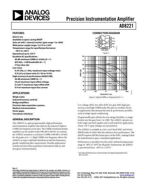
Precision Instrumentation Amplifier<strong>AD8221</strong>FEATURESEasy to useAvailable in space-saving MSOPGain set with 1 external resistor (gain range 1 to 1000)Wide power supply range: ±2.3 V to ±18 VTemperature range for specified performance:−40°C to +85°COperational up to 125°C 1Excellent AC specifications80 dB minimum CMRR to 10 kHz (G = 1)825 kHz, –3 dB bandwidth (G = 1)2 V/µs slew rateLow noise8 nV/√Hz, @ 1 kHz, maximum input voltage noise0.25 µV p-p input noise (0.1 Hz to 10 Hz)High accuracy dc performance (<strong>AD8221</strong>BR)90 dB minimum CMRR (G = 1)25 µV maximum input offset voltage0.3 µV/°C maximum input offset drift0.4 nA maximum input bias currentAPPLICATIONSWeigh scalesIndustrial process controlsBridge amplifiersPrecision data acquisition systemsMedical instrumentationStrain gagesTransducer interfacesGENERAL DESCRIPTIONThe <strong>AD8221</strong> is a gain programmable, high performanceinstrumentation amplifier that delivers the industry’s highestCMRR over frequency in its class. The CMRR of instrumentationamplifiers on the market today falls off at 200 Hz. In contrast,the <strong>AD8221</strong> maintains a minimum CMRR of 80 dB to 10 kHzfor all grades at G = 1. High CMRR over frequency allows the<strong>AD8221</strong> to reject wideband interference and line harmonics,greatly simplifying filter requirements. Possible applicationsinclude precision data acquisition, biomedical analysis, andaerospace instrumentation.CMRR (dB)1201101009080706050CONNECTION DIAGRAM–IN 1R G2R G3+IN 4<strong>AD8221</strong>TOP VIEWFigure 1.8 +V S7 V OUT6 REF5 –V S<strong>AD8221</strong>4010 1001k 10k 100kFREQUENCY (Hz)03149-001COMPETITOR 1COMPETITOR 2Figure 2. Typical CMRR vs. Frequency for G = 1Low voltage offset, low offset drift, low gain drift, high gainaccuracy, and high CMRR make this part an excellent choicein applications that demand the best dc performance possible,such as bridge signal conditioning.Programmable gain affords the user design flexibility. A singleresistor sets the gain from 1 to 1000. The <strong>AD8221</strong> operates onboth single and dual supplies and is well suited for applicationswhere ±10 V input voltages are encountered.The <strong>AD8221</strong> is available in a low cost 8-lead SOIC and 8-leadMSOP, both of which offer the industry’s best performance. TheMSOP requires half the board space of the SOIC, making it idealfor multichannel or space-constrained applications.Performance is specified over the entire industrial temperaturerange of −40°C to +85°C for all grades. Furthermore, the <strong>AD8221</strong>is operational from −40°C to +125°C 1 .03149-0021See Typical Performance Characteristics for expected operation from85°C to 125°C.<strong>Rev</strong>. CInformation furnished by <strong>Analog</strong> <strong>Devices</strong> is believed to be accurate and reliable. However, noresponsibility is assumed by <strong>Analog</strong> <strong>Devices</strong> for its use, nor for any infringements of patents or otherrights of third parties that may result from its use. Specifications subject to change without notice. Nolicense is granted by implication or otherwise under any patent or patent rights of <strong>Analog</strong> <strong>Devices</strong>.Trademarks and registered trademarks are the property of their respective owners.One Technology Way, P.O. Box 9106, Norwood, MA 02062-9106, U.S.A.Tel: 781.329.4700www.analog.comFax: 781.461.3113 ©2003–2011 <strong>Analog</strong> <strong>Devices</strong>, Inc. All rights reserved.
<strong>AD8221</strong>TABLE OF CONTENTSFeatures .............................................................................................. 1Applications ....................................................................................... 1General Description ......................................................................... 1Connection Diagram ....................................................................... 1<strong>Rev</strong>ision History ............................................................................... 2Specifications ..................................................................................... 3Absolute Maximum Ratings ............................................................ 8Thermal Characteristics .............................................................. 8ESD Caution .................................................................................. 8Pin Configuration and Function Descriptions ............................. 9Typical Performance Characteristics ........................................... 10Theory of Operation ...................................................................... 17Gain Selection ............................................................................. 18Layout .......................................................................................... 18Reference Terminal .................................................................... 19Power Supply Regulation and Bypassing ................................ 19Input Bias Current Return Path ............................................... 19Input Protection ......................................................................... 19RF Interference ........................................................................... 20Precision Strain Gage ................................................................. 20Conditioning ±10 V Signals for a +5 V Differential InputADC ............................................................................................. 20AC-Coupled Instrumentation Amplifier ................................ 21Die Information .............................................................................. 22Outline Dimensions ....................................................................... 23Ordering Guide .......................................................................... 24REVISION HISTORY3/11—<strong>Rev</strong>. B to <strong>Rev</strong>. CAdded Pin Configuration and Function Descriptions Section .. 9Added Die Information Section ................................................... 22Updated Outline Dimensions ....................................................... 23Changes to Ordering Guide .......................................................... 249/07—<strong>Rev</strong>. A to <strong>Rev</strong>. BChanges to Features .......................................................................... 1Changes to Table 1 Layout ............................................................... 3Changes to Table 2 Layout ............................................................... 5Changes to Figure 15 ...................................................................... 11Changes to Figures 32 .................................................................... 13Changes to Figure 33, Figure 34, and Figure 35 ......................... 14Updated Outline Dimensions ....................................................... 21Changes to Ordering Guide .......................................................... 2211/03—<strong>Rev</strong>. 0 to <strong>Rev</strong>. AChanges to Features .......................................................................... 1Changes to Specifications Section .................................................. 4Changes to Theory of Operation Section .................................... 13Changes to Gain Selection Section............................................... 1410/03—<strong>Rev</strong>ision 0: Initial Version<strong>Rev</strong>. C | Page 2 of 24
<strong>AD8221</strong>SPECIFICATIONSVS = ±15 V, VREF = 0 V, TA = 25°C, G = 1, RL = 2 kΩ, unless otherwise noted.Table 1.AR GradeBR GradeParameter Conditions Min Typ Max Min Typ Max UnitCOMMON-MODE REJECTION RATIOCMRR DC to 60 Hz with 1 kΩ VCM = −10 V to +10 VSource ImbalanceG = 1 80 90 dBG = 10 100 110 dBG = 100 120 130 dBG = 1000 130 140 dBCMRR at 10 kHzVCM = −10 V to +10 VG = 1 80 80 dBG = 10 90 100 dBG = 100 100 110 dBG = 1000 100 110 dBNOISE RTI noise =√eNI 2 + (eNO/G) 2Voltage Noise, 1 kHzInput Voltage Noise, eNI VIN+, VIN−, VREF = 0 8 8 nV/√HzOutput Voltage Noise, eNO 75 75 nV/√HzRTIf = 0.1 Hz to 10 HzG = 1 2 2 μV p-pG = 10 0.5 0.5 μV p-pG = 100 to 1000 0.25 0.25 μV p-pCurrent Noise f = 1 kHz 40 40 fA/√Hzf = 0.1 Hz to 10 Hz 6 6 pA p-pVOLTAGE OFFSET 1Input Offset, VOSI VS = ±5 V to ±15 V 60 25 μVOver Temperature T = −40°C to +85°C 86 45 μVAverage TC 0.4 0.3 μV/°COutput Offset, VOSO VS = ±5 V to ±15 V 300 200 μVOver Temperature T = −40°C to +85°C 0.66 0.45 mVAverage TC 6 5 μV/°COffset RTI vs. Supply (PSR) VS = ±2.3 V to ±18 VG = 1 90 110 94 110 dBG = 10 110 120 114 130 dBG = 100 124 130 130 140 dBG = 1000 130 140 140 150 dBINPUT CURRENTInput Bias Current 0.5 1.5 0.2 0.4 nAOver Temperature T = −40°C to +85°C 2.0 1 nAAverage TC 1 1 pA/°CInput Offset Current 0.2 0.6 0.1 0.4 nAOver Temperature T = −40°C to +85°C 0.8 0.6 nAAverage TC 1 1 pA/°CREFERENCE INPUTRIN 20 20 kΩIIN VIN+, VIN−, VREF = 0 50 60 50 60 μAVoltage Range –VS +VS –VS +VS VGain to Output 1 ± 0.0001 1 ± 0.0001 V/V<strong>Rev</strong>. C | Page 3 of 24
<strong>AD8221</strong>AR GradeBR GradeParameter Conditions Min Typ Max Min Typ Max UnitPOWER SUPPLYOperating Range V S = ±2.3 V to ±18 V ±2.3 ±18 ±2.3 ±18 VQuiescent Current 0.9 1 0.9 1 mAOver Temperature T = −40°C to +85°C 1 1.2 1 1.2 mADYNAMIC RESPONSESmall Signal −3 dB BandwidthG = 1 825 825 kHzG = 10 562 562 kHzG = 100 100 100 kHzG = 1000 14.7 14.7 kHzSettling Time 0.01%10 V stepG = 1 to 100 10 10 µsG = 1000 80 80 µsSettling Time 0.001%10 V stepG = 1 to 100 13 13 µsG = 1000 110 110 µsSlew Rate G = 1 1.5 2 1.5 2 V/µsG = 5 to 100 2 2.5 2 2.5 V/µsGAIN G = 1 + (49.4 kΩ/R G )Gain Range 1 1000 1 1000 V/VGain ErrorV OUT ± 10 VG = 1 0.03 0.02 %G = 10 0.3 0.15 %G = 100 0.3 0.15 %G = 1000 0.3 0.15 %Gain NonlinearityV OUT = −10 V to +10 VG = 1 to 10 R L = 10 kΩ 3 10 3 10 ppmG = 100 R L = 10 kΩ 5 15 5 15 ppmG = 1000 R L = 10 kΩ 10 40 10 40 ppmG = 1 to 100 R L = 2 kΩ 10 95 10 95 ppmGain vs. TemperatureG = 1 3 10 2 5 ppm/°CG > 1 2 –50 –50 ppm/°CINPUTInput ImpedanceDifferential 100||2 100||2 GΩ||pFCommon Mode 100||2 100||2 GΩ||pFInput Operating Voltage Range 3 V S = ±2.3 V to ±5 V –V S + 1.9 +V S − 1.1 –V S + 1.9 +V S − 1.1 VOver Temperature T = −40°C to +85°C –V S + 2.0 +V S − 1.2 –V S + 2.0 +V S − 1.2 VInput Operating Voltage Range V S = ±5 V to ±18 V –V S + 1.9 +V S − 1.2 –V S + 1.9 +V S − 1.2 VOver Temperature T =−40°C to +85°C –V S + 2.0 +V S − 1.2 –V S + 2.0 +V S − 1.2 VOUTPUTR L = 10 kΩOutput Swing V S = ±2.3 V to ±5 V –V S + 1.1 +V S − 1.2 –V S + 1.1 +V S − 1.2 VOver Temperature T = −40°C to +85°C –V S + 1.4 +Vs − 1.3 –V S + 1.4 +V S − 1.3 VOutput Swing V S = ±5 V to ±18 V –V S + 1.2 +V S − 1.4 –V S + 1.2 +V S − 1.4 VOver Temperature T = –40°C to +85°C –V S + 1.6 +V S − 1.5 –V S + 1.6 +V S − 1.5 VShort-Circuit Current 18 18 mA<strong>Rev</strong>. C | Page 4 of 24
<strong>AD8221</strong>AR GradeBR GradeParameter Conditions Min Typ Max Min Typ Max UnitTEMPERATURE RANGESpecified Performance –40 +85 –40 +85 °COperating Range 4 –40 +125 –40 +125 °C1Total RTI V OS = (V OSI ) + (V OSO /G).2Does not include the effects of external resistor R G .3One input grounded. G = 1.4See Typical Performance Characteristics for expected operation between 85°C to 125°C.Table 2.ParameterConditionsMinARM GradeTyp MaxUnitCOMMON-MODE REJECTION RATIO (CMRR)CMRR DC to 60 Hz with 1 kΩ Source Imbalance V CM = −10 V to +10 VG = 1 80 dBG = 10 100 dBG = 100 120 dBG = 1000 130 dBCMRR at 10 kHzV CM = –10 V to +10 VG = 1 80 dBG = 10 90 dBG = 100 100 dBG = 1000 100 dBNOISE RTI noise =2√e NI + (e NO /G) 2Voltage Noise, 1 kHzInput Voltage Noise, e NI V IN+ , V IN− , V REF = 0 8 nV/√HzOutput Voltage Noise, e NO 75 nV/√HzRTIf = 0.1 Hz to 10 HzG = 1 2 µV p-pG = 10 0.5 µV p-pG = 100 to 1000 0.25 µV p-pCurrent Noise f = 1 kHz 40 fA/√Hzf = 0.1 Hz to 10 Hz 6 pA p-pVOLTAGE OFFSET 1Input Offset, V OSI V S = ±5 V to ±15 V 70 µVOver Temperature T = −40°C to +85°C 135 µVAverage TC 0.9 µV/°COutput Offset, V OSO V S = ±5 V to ±15 V 600 µVOver Temperature T = −40°C to +85°C 1.00 mVAverage TC 9 µV/°COffset RTI vs. Supply (PSR)V S = ±2.3 V to ±18 VG = 1 90 100 dBG = 10 100 120 dBG = 100 120 140 dBG = 1000 120 140 dBINPUT CURRENTInput Bias Current 0.5 2 nAOver Temperature T = −40°C to +85°C 3 nAAverage TC 3 pA/°CInput Offset Current 0.3 1 nAOver Temperature T = −40°C to +85°C 1.5 nAAverage TC 3 pA/°C<strong>Rev</strong>. C | Page 5 of 24
<strong>AD8221</strong>ParameterConditionsMinARM GradeTyp MaxUnitREFERENCE INPUTR IN 20 kΩI IN V IN+ , V IN− , V REF = 0 50 60 µAVoltage Range −V S +V S VGain to Output 1 ± 0.0001 V/VPOWER SUPPLYOperating Range V S = ±2.3 V to ±18 V ±2.3 ±18 VQuiescent Current 0.9 1 mAOver Temperature T = −40°C to +85°C 1 1.2 mADYNAMIC RESPONSESmall Signal –3 dB BandwidthG = 1 825 kHzG = 10 562 kHzG = 100 100 kHzG = 1000 14.7 kHzSettling Time 0.01%10 V stepG = 1 to 100 10 µsG = 1000 80 µsSettling Time 0.001%10 V stepG = 1 to 100 13 µsG = 1000 110 µsSlew Rate G = 1 1.5 2 V/µsG = 5 to 100 2 2.5 V/µsGAIN G = 1 + (49.4 kΩ/R G )Gain Range 1 1000 V/VGain ErrorV OUT ± 10 VG = 1 0.1 %G = 10 0.3 %G = 100 0.3 %G = 1000 0.3 %Gain NonlinearityV OUT = −10 V to +10 VG = 1 to 10 R L = 10 kΩ 5 15 ppmG = 100 R L = 10 kΩ 7 20 ppmG = 1000 R L = 10 kΩ 10 50 ppmG = 1 to 100 R L = 2 kΩ 15 100 ppmGain vs. TemperatureG = 1 3 10 ppm/°CG > 1 2 –50 ppm/°CINPUTInput ImpedanceDifferential 100||2 GΩ/pFCommon Mode 100||2 GΩ/pFInput Operating Voltage Range 3 V S = ±2.3 V to ±5 V –V S + 1.9 +V S − 1.1 VOver Temperature T = −40°C to +85°C –V S + 2.0 +V S − 1.2 VInput Operating Voltage Range V S = ±5 V to ±18 V –V S + 1.9 +V S − 1.2 VOver Temperature T = −40°C to +85°C –V S + 2.0 +V S − 1.2 VOUTPUTR L = 10 kΩOutput Swing V S = ±2.3 V to ±5 V –V S + 1.1 +V S − 1.2 VOver Temperature T = −40°C to +85°C –V S + 1.4 +V S − 1.3 VOutput Swing V S = ±5 V to ±18 V –V S + 1.2 +V S − 1.4 VOver Temperature T = −40°C to +85°C –V S + 1.6 +V S − 1.5 VShort-Circuit Current 18 mA<strong>Rev</strong>. C | Page 6 of 24
<strong>AD8221</strong>ParameterConditionsMinARM GradeTyp MaxUnitTEMPERATURE RANGESpecified Performance −40 +85 °COperating Range 4 −40 +125 °C1Total RTI V OS = (V OSI ) + (V OSO /G).2Does not include the effects of external resistor R G .3One input grounded. G = 1.4See Typical Performance Characteristics for expected operation between 85°C to 125°C.<strong>Rev</strong>. C | Page 7 of 24
<strong>AD8221</strong>ABSOLUTE MAXIMUM RATINGSTable 3.ParameterSupply VoltageInternal Power DissipationOutput Short-Circuit CurrentInput Voltage (Common-Mode)Differential Input VoltageStorage Temperature RangeOperating Temperature Range 1Rating±18 V200 mWIndefinite±V S±V S−65°C to +150°C−40°C to +125°C1Temperature range for specified performance is –40°C to +85°C. See TypicalPerformance Characteristics for expected operation from 85°C to 125°C.Stresses above those listed under Absolute Maximum Ratingsmay cause permanent damage to the device. This is a stressrating only; functional operation of the device at these or anyother conditions above those indicated in the operationalsection of this specification is not implied. Exposure to absolutemaximum rating conditions for extended periods may affectdevice reliability.THERMAL CHARACTERISTICSSpecification for a device in free air.Table 4.Package θ JA Unit8-Lead SOIC, 4-Layer JEDEC Board 121 °C/W8-Lead MSOP, 4-Layer JEDEC Board 135 °C/WESD CAUTION<strong>Rev</strong>. C | Page 8 of 24
<strong>AD8221</strong>PIN CONFIGURATION AND FUNCTION DESCRIPTIONS<strong>AD8221</strong>–IN 18 +V SR G 2R G 3+IN 4765V OUTREF–V STOP VIEW(Not to Scale)Figure 3. Pin Configuration03149-103Table 5. Pin Function DescriptionsPin No. Mnemonic Description1 −IN Negative Input Terminal.2 R G Gain Setting Terminal. Place resistor across the R G pins to set the gain. G = 1 + (49.4 kΩ/R G ).3 R G Gain Setting Terminal. Place resistor across the R G pins to set the gain. G = 1 + (49.4 kΩ/R G ).4 +IN Positive Input Terminal.5 −V S Negative Power Supply Terminal.6 REF Reference Voltage Terminal. Drive this terminal with a low impedance voltage source to level-shift the output.7 V OUT Output Terminal.8 +V S Positive Power Supply Terminal.<strong>Rev</strong>. C | Page 9 of 24
<strong>AD8221</strong>TYPICAL PERFORMANCE CHARACTERISTICST = 25°C, V S = ±15 V, R L = 10 kΩ, unless otherwise noted.16003500UNITS140012001000800600400200UNITS300025002000150010005000–150 –100 –50 0 50 100 150CMR (µV/V)Figure 4. Typical Distribution for CMR (G = 1)03149-0030–0.9 –0.6 –0.3 0 0.3 0.6 0.9INPUT OFFSET CURRENT (nA)Figure 7. Typical Distribution of Input Offset Current03149-006240015UNITS2100180015001200900600300INPUT COMMON-MODE VOLTAGE (V)1050–5–10V S = ±5VV S = ±15V0–60 –40 –20 0 20 40 60INPUT OFFSET VOLTAGE (µV)Figure 5. Typical Distribution of Input Offset Voltage03149-004–15–15 –10 –5 0 5 10 15OUTPUT VOLTAGE (V)Figure 8. Input Common-Mode Range vs. Output Voltage, G = 103149-007300015UNITS2500200015001000500INPUT COMMON-MODE VOLTAGE (V)1050–5–10V S = ±5VV S = ±15V0–1.5 –1.0 –0.5 0 0.5 1.0 1.5INPUT BIAS CURRENT (nA)Figure 6. Typical Distribution of Input Bias Current03149-005–15–15 –10 –5 0 5 10 15OUTPUT VOLTAGE (V)Figure 9. Input Common-Mode Range vs. Output Voltage, G = 10003149-008<strong>Rev</strong>. C | Page 10 of 24
<strong>AD8221</strong>0.801800.75160GAIN = 1000INPUT BIAS CURRENT (nA)0.700.650.600.550.50V S = ±15VV S = ±5VPOSITIVE PSRR (dB)1401201008060GAIN = 100GAIN = 10GAIN = 1GAIN = 10000.45400.40–15 –10 –5 0 5 10 15COMMON-MODE VOLTAGE (V)Figure 10. I BIAS vs. CMV03149-009200.1 1 10 100 1k 10k 100k 1MFREQUENCY (Hz)Figure 13. Positive PSRR vs. Frequency, RTI (G = 1 to 1000)03149-0122.00180CHANGE IN INPUT OFFSET VOLTAGE (µV)1.751.501.251.000.750.500.25NEGATIVE PSRR (dB)160140120100806040GAIN = 1000GAIN = 100GAIN = 10GAIN = 100.01 0.11 10WARM-UP TIME (min)Figure 11. Change in Input Offset Voltage vs. Warm-Up Time03149-010200.1 1 10 100 1k 10k 100k 1MFREQUENCY (Hz)Figure 14. Negative PSRR vs. Frequency, RTI (G = 1 to 1000)03149-01354VS = ±15V100kINPUT CURRENT (nA)3210–1INPUT OFFSET CURRENTINPUT BIAS CURRENT–2–3–4–5–40 –20 0 20 40 60 80 100 120 140TEMPERATURE (°C)Figure 12. Input Bias Current and Offset Current vs. Temperature03149-011TOTAL DRIFT 25°C – 85°C RTI (µV)10k1k100BEST AVAILABLE FETINPUT IN-AMP GAIN = 1BEST AVAILABLE FETINPUT IN-AMP GAIN = 1000<strong>AD8221</strong> GAIN = 11010 100 1k 10k 100k 1M 10MSOURCE RESISTANCE (Ω)<strong>AD8221</strong> GAIN = 1000Figure 15. Total Drift vs. Source Resistance03149-014<strong>Rev</strong>. C | Page 11 of 24
<strong>AD8221</strong>7060GAIN = 1000100805040GAIN = 1006040GAIN (dB)3020100GAIN = 10GAIN = 1CMR (µV/V)200–20–40–10–60–20–80–30100 1k 10k 100k 1M 10MFREQUENCY (Hz)Figure 16. Gain vs. Frequency03149-015–100–40 –20 0 20 40 60 80 100 120 140TEMPERATURE (°C)Figure 19. CMR vs. Temperature03149-018CMRR (dB)160140120100GAIN = 1000GAIN = 100GAIN = 10GAIN = 18060400.1 1 10 100 1k 10k 100k 1MFREQUENCY (Hz)Figure 17. CMRR vs. Frequency, RTI03149-016+V S –0INPUT VOLTAGE LIMIT (V)REFERRED TO SUPPLY VOLTAGES–0.4–0.8–1.2–1.6–2.0–2.4+2.4+2.0+1.6+1.2+0.8+0.4–V S +00 510 15 20SUPPLY VOLTAGE (±V)Figure 20. Input Voltage Limit vs. Supply Voltage, G = 103149-019CMRR (dB)160140120100GAIN = 1000GAIN = 100GAIN = 10GAIN = 18060400.1 1 10 100 1k 10k 100k 1MFREQUENCY (Hz)Figure 18. CMRR vs. Frequency, RTI, 1 kΩ Source Imbalance03149-017+V S –0OUTPUT VOLTAGE SWING (V)REFERRED TO SUPPLY VOLTAGES–0.4–0.8–1.2–1.6–2.0+2.0+1.6+1.2+0.8+0.4R L = 10kΩR L = 2kΩR L = 2kΩR L = 10kΩ–V S +00 510 15 20SUPPLY VOLTAGE (±V)Figure 21. Output Voltage Swing vs. Supply Voltage, G = 103149-020<strong>Rev</strong>. C | Page 12 of 24
<strong>AD8221</strong>30V S = ±15VV S = ±15VOUTPUT VOLTAGE SWING (V p-p)2010ERROR (10ppm/DIV)01 10100 1k 10kLOAD RESISTANCE (Ω)Figure 22. Output Voltage Swing vs. Load Resistance03149-021–10 –8 –6 –4 –2 0 2 4 6 8 10OUTPUT VOLTAGE (V)Figure 25. Gain Nonlinearity, G = 100, R L = 10 kΩ03149-024+V S –0V S = ±15V–1OUTPUT VOLTAGE SWING (V)REFERRED TO SUPPLY VOLTAGES–2–3+3+2+1SOURCINGSINKINGERROR (100ppm/DIV)–V S +00 1 2 3 4 5 6 7 8 9 10 11 12OUTPUT CURRENT (mA)Figure 23. Output Voltage Swing vs. Output Current, G = 103149-022–10 –8 –6 –4 –2 0 2 4 6 8 10OUTPUT VOLTAGE (V)Figure 26. Gain Nonlinearity, G = 1000, R L = 10 kΩ03149-025V S = ±15V1kERROR (1ppm/DIV)VOLTAGE NOISE RTI (nV/ Hz)10010GAIN = 1GAIN = 10GAIN = 100GAIN = 1000GAIN = 1000BW LIMIT–10 –8 –6 –4 –2 0 2 4 6 8 10OUTPUT VOLTAGE (V)Figure 24. Gain Nonlinearity, G = 1, R L = 10 kΩ03149-02311 10 100 1k 10k 100kFREQUENCY (Hz)Figure 27. Voltage Noise Spectral Density vs. Frequency (G = 1 to 1000)03149-026<strong>Rev</strong>. C | Page 13 of 24
<strong>AD8221</strong>2µV/DIV1s/DIVFigure 28. 0.1 Hz to 10 Hz RTI Voltage Noise (G = 1)03149-0275pA/DIVFigure 31. 0.1 Hz to 10 Hz Current Noise1s/DIV03149-03030V S = ±15V25OUTPUT VOLTAGE (V p-p)2015105GAIN = 1 GAIN = 10, 100, 10000.1µV/DIV1s/DIV03149-02801k10kFREQUENCY (Hz)100k1M03149-031Figure 29. 0.1 Hz to 10 Hz RTI Voltage Noise (G = 1000)Figure 32. Large Signal Frequency Response1kCURRENT NOISE (fA/ Hz)1005V/DIV0.002%/DIV7.9µs TO 0.01%8.5µs TO 0.001%101 10100 1k 10kFREQUENCY (Hz)03149-02920µs/DIV03149-032Figure 30. Current Noise Spectral Density vs. FrequencyFigure 33. Large Signal Pulse Response and Settling Time (G = 1), 0.002%/DIV<strong>Rev</strong>. C | Page 14 of 24
<strong>AD8221</strong>5V/DIV0.002%/DIV4.9µs TO 0.01%5.6µs TO 0.001%20mV/DIV20µs/DIVFigure 34. Large Signal Pulse Response and Settling Time (G = 10),0.002%/DIV03149-0334µs/DIVFigure 37. Small Signal Response, G = 1, R L = 2 kΩ, C L = 100 pF03149-0365V/DIV0.002%/DIV10.3µs TO 0.01%13.4µs TO 0.001%20mV/DIV20µs/DIVFigure 35. Large Signal Pulse Response and Settling Time (G = 100),0.002%/DIV03149-0344µs/DIVFigure 38. Small Signal Response, G = 10, R L = 2 kΩ, C L = 100 pF03149-0375V/DIV0.002%/DIV83µs TO 0.01%112µs TO 0.001%20mV/DIV200µs/DIVFigure 36. Large Signal Pulse Response and Settling Time (G = 1000),0.002%/DIV03149-03510µs/DIVFigure 39. Small Signal Response, G = 100, R L = 2 kΩ, C L = 100 pF03149-038<strong>Rev</strong>. C | Page 15 of 24
<strong>AD8221</strong>10002SETTLING TIME (µs)10010SETTLED TO 0.001%20mV/DIVSETTLED TO 0.01%100µs/DIV03149-03911 10 1001000GAIN03149-041Figure 40. Small Signal Response, G = 1000, R L = 2 kΩ, C L = 100 pFFigure 42. Settling Time vs. Gain for a 10 V Step15SETTLING TIME (µs)105SETTLED TO 0.001%SETTLED TO 0.01%00 510 15 20OUTPUT VOLTAGE STEP SIZE (V)Figure 41. Settling Time vs. Step Size (G = 1)03149-040<strong>Rev</strong>. C | Page 16 of 24
<strong>AD8221</strong>THEORY OF OPERATIONII B COMPENSATIONA1A2C1C2+V S–V SR1 24.7kΩ R2 24.7kΩ400Ω+V S–INQ1R G+V SV BQ2II B COMPENSATION–V S10kΩ10kΩA310kΩ+V S400Ω+V S+IN10kΩ+V S–V SOUTPUTREF–V S–V S–V S03149-042Figure 43. Simplified SchematicThe <strong>AD8221</strong> is a monolithic instrumentation amplifier basedon the classic 3-op amp topology. Input transistors Q1 and Q2are biased at a fixed current so that any differential input signalforces the output voltages of A1 and A2 to change accordingly.A signal applied to the input creates a current through R G , R1,and R2, such that the outputs of A1 and A2 deliver the correctvoltage. Topologically, Q1, A1, R1 and Q2, A2, R2 can beviewed as precision current feedback amplifiers. The amplifieddifferential and common-mode signals are applied to adifference amplifier that rejects the common-mode voltagebut amplifies the differential voltage. The difference amplifieremploys innovations that result in low output offset voltage aswell as low output offset voltage drift. Laser-trimmed resistorsallow for a highly accurate in-amp with gain error typically lessthan 20 ppm and CMRR that exceeds 90 dB (G = 1).Using superbeta input transistors and an I B compensationscheme, the <strong>AD8221</strong> offers extremely high input impedance,low I B , low I B drift, low I OS , low input bias current noise, andextremely low voltage noise of 8 nV/√Hz.The transfer function of the <strong>AD8221</strong> is49.4 kΩG = 1+RGUsers can easily and accurately set the gain using a singlestandard resistor.Because the input amplifiers employ a current feedbackarchitecture, the gain-bandwidth product of the <strong>AD8221</strong>increases with gain, resulting in a system that does not sufferfrom the expected bandwidth loss of voltage feedbackarchitectures at higher gains.To maintain precision even at low input levels, special attentionwas given to the design and layout of the <strong>AD8221</strong>, resulting inan in-amp whose performance satisfies the most demandingapplications.A unique pinout enables the <strong>AD8221</strong> to meet a CMRRspecification of 80 dB at 10 kHz (G = 1) and 110 dB at 1 kHz(G = 1000). The balanced pinout, shown in Figure 44, reducesthe parasitics that had, in the past, adversely affected CMRRperformance. In addition, the new pinout simplifies boardlayout because associated traces are grouped together. Forexample, the gain setting resistor pins are adjacent to theinputs, and the reference pin is next to the output.–INR GR G+IN1234<strong>AD8221</strong>TOP VIEW8765+V SV OUTREF–V SFigure 44. Pinout Diagram03149-043<strong>Rev</strong>. C | Page 17 of 24
<strong>AD8221</strong>GAIN SELECTIONPlacing a resistor across the R G terminals set the gain of<strong>AD8221</strong>, which can be calculated by referring to Table 6 orby using the gain equation.RG49.4 kΩ= G − 1Table 6. Gains Achieved Using 1% Resistors1% Standard Table Value of R G (Ω) Calculated Gain49.9 k 1.99012.4 k 4.9845.49 k 9.9982.61 k 19.931.00 k 50.40499 100.0249 199.4100 495.049.9 991.0GroundingThe output voltage of the <strong>AD8221</strong> is developed with respect tothe potential on the reference terminal. Care should be taken totie REF to the appropriate local ground.In mixed-signal environments, low level analog signals need tobe isolated from the noisy digital environment. Many ADCshave separate analog and digital ground pins. Although it isconvenient to tie both grounds to a single ground plane, thecurrent traveling through the ground wires and PC board maycause hundreds of millivolts of error. Therefore, separate analogand digital ground returns should be used to minimize thecurrent flow from sensitive points to the system ground. Anexample layout is shown in Figure 45 and Figure 46.The <strong>AD8221</strong> defaults to G = 1 when no gain resistor is used.Gain accuracy is determined by the absolute tolerance of R G .The TC of the external gain resistor increases the gain drift ofthe instrumentation amplifier. Gain error and gain drift are keptto a minimum when the gain resistor is not used.LAYOUTCareful board layout maximizes system performance. Tracesfrom the gain setting resistor to the R G pins should be kept asshort as possible to minimize parasitic inductance. To ensurethe most accurate output, the trace from the REF pin shouldeither be connected to the local ground of the <strong>AD8221</strong>, as shownin Figure 47, or connected to a voltage that is referenced to thelocal ground of the <strong>AD8221</strong>.Common-Mode RejectionOne benefit of the high CMRR over frequency of the <strong>AD8221</strong> isthat it has greater immunity to disturbances, such as line noiseand its associated harmonics, than do typical instrumentationamplifiers. Typically, these amplifiers have CMRR fall-off at200 Hz; common-mode filters are often used to compensate forthis shortcoming. The <strong>AD8221</strong> is able to reject CMRR over agreater frequency range, reducing the need for filtering.A well implemented layout helps to maintain the high CMRRover frequency of the <strong>AD8221</strong>. Input source impedance andcapacitance should be closely matched. In addition, sourceresistance and capacitance should be placed as close to theinputs as permissible.Figure 45. Top Layer of the <strong>AD8221</strong>-EVALFigure 46. Bottom Layer of the <strong>AD8221</strong>-EVAL03149-04403149-045<strong>Rev</strong>. C | Page 18 of 24
<strong>AD8221</strong>REFERENCE TERMINALAs shown in Figure 43, the reference terminal, REF, is at oneend of a 10 kΩ resistor. The output of the instrumentationamplifier is referenced to the voltage on the REF terminal; thisis useful when the output signal needs to be offset to a precisemidsupply level. For example, a voltage source can be tied to theREF pin to level-shift the output so that the <strong>AD8221</strong> can interfacewith an ADC. The allowable reference voltage range is a functionof the gain, input, and supply voltage. The REF pin should notexceed either +V S or –V S by more than 0.5 V.For best performance, source impedance to the REF terminalshould be kept low, because parasitic resistance can adverselyaffect CMRR and gain accuracy.POWER SUPPLY REGULATION AND BYPASSINGA stable dc voltage should be used to power the instrumentationamplifier. Noise on the supply pins can adversely affectperformance. Bypass capacitors should be used to decouplethe amplifier.A 0.1 µF capacitor should be placed close to each supply pin.As shown in Figure 47, a 10 µF tantalum capacitor can be usedfurther away from the part. In most cases, it can be shared byother precision integrated circuits.+V S1f HIGH-PASS = 2πRC–V STRANSFORMER–V STHERMOCOUPLECRC+V SREF<strong>AD8221</strong>+V SREF<strong>AD8221</strong>+V SREF<strong>AD8221</strong>0.1µF 10µFR+IN–INV OUT<strong>AD8221</strong>LOADREF0.1µF 10µF–V SFigure 47. Supply Decoupling, REF, and Output Referred to Local GroundINPUT BIAS CURRENT RETURN PATHThe input bias current of the <strong>AD8221</strong> must have a return pathto common. When the source, such as a thermocouple, cannotprovide a return current path, one should be created, as shownin Figure 48.03149-046–V SCAPACITOR COUPLEDFigure 48. Creating an I BIAS PathINPUT PROTECTIONAll terminals of the <strong>AD8221</strong> are protected against ESD, 1 kVHuman Body Model. In addition, the input structure allows fordc overload conditions below the negative supply, −V S . Theinternal 400 Ω resistors limit current in the event of a negativefault condition. However, in the case of a dc overload voltageabove the positive supply, +V S , a large current flows directlythrough the ESD diode to the positive rail. Therefore, an externalresistor should be used in series with the input to limit currentfor voltages above +Vs. In either scenario, the <strong>AD8221</strong> cansafely handle a continuous 6 mA current, I = V IN /R EXT forpositive overvoltage and I = V IN /(400 Ω + R EXT ) for negativeovervoltage.For applications where the <strong>AD8221</strong> encounters extremeoverload voltages, as in cardiac defibrillators, external seriesresistors, and low leakage diode clamps, such as BAV199Ls,FJH1100s, or SP720s should be used.03149-047<strong>Rev</strong>. C | Page 19 of 24
<strong>AD8221</strong>RF INTERFERENCERF rectification is often a problem when amplifiers are used inapplications where there are strong RF signals. The disturbancecan appear as a small dc offset voltage. High frequency signalscan be filtered with a low-pass RC network placed at the inputof the instrumentation amplifier, as shown in Figure 49. Thefilter limits the input signal bandwidth according to the followingrelationship:FilterFreqDiff1=2πR(2C1FilterFreqCM=2πRCwhere C D ≥ 10C C .10µF10µFR4.02kΩRC CC D4.02kΩC C0.1µF0.1µF+IN–IN1nFCD+ CC)0.1µFR110nF499Ω1nF+IN–IN+15V<strong>AD8221</strong>REF10µF0.1µF 10µF–15VFigure 49. RFI Suppression+12V<strong>AD8221</strong>–12VREFR110kΩR210kΩ+2.5V+12VV OUT0.1µFOP27–12V0.1µF03149-048R31kΩR5499ΩR41kΩC1470pFC D affects the difference signal, and C C affects the commonmodesignal. Values of R and C C should be chosen to minimizeRFI. Mismatch between the R × C C at the positive input and theR × C C at the negative input degrades the CMRR of the <strong>AD8221</strong>.By using a value of C D one magnitude larger than C C , the effectof the mismatch is reduced, and therefore, performance isimproved.PRECISION STRAIN GAGEThe low offset and high CMRR over frequency of the <strong>AD8221</strong>make it an excellent candidate for bridge measurements. Asshown in Figure 50, the bridge can be directly connected tothe inputs of the amplifier.350Ω350Ω350Ω350Ω10µF 0.1µF+5V+IN+Figure 50. Precision Strain GageR <strong>AD8221</strong>––IN+2.5VCONDITIONING ±10 V SIGNALS FOR A +5 VDIFFERENTIAL INPUT ADCThere is a need in many applications to condition ±10 V signals.However, many of today’s ADCs and digital ICs operate onmuch lower, single-supply voltages. Furthermore, new ADCshave differential inputs because they provide better commonmoderejection, noise immunity, and performance at low supplyvoltages. Interfacing a ±10 V, single-ended instrumentationamplifier to a +5 V, differential ADC can be a challenge.Interfacing the instrumentation amplifier to the ADC requiresattenuation and a level shift. A solution is shown in Figure 51.+12V0.1µFAD8022(½)0.1µF–12V+12V0.1µFAD8022(½)R627.4ΩC2220µFR727.4Ω220nF10nFVIN(+)+5V +5V10nFAV DDAD7723DV DDVIN(–)AGND DGND REF1 REF203149-0490.1µF–12V2.5V+5V+V IN V OUT10µF 0.1µF AD780 22µFGND03149-050Figure 51. Interfacing to a Differential Input ADC<strong>Rev</strong>. C | Page 20 of 24
<strong>AD8221</strong>In this topology, an OP27 sets the reference voltage of the<strong>AD8221</strong>. The output signal of the instrumentation amplifier istaken across the OUT pin and the REF pin. Two 1 kΩ resistorsand a 499 Ω resistor attenuate the ±10 V signal to +4 V. Anoptional capacitor, C1, can serve as an antialiasing filter. AnAD8022 is used to drive the ADC.This topology has five benefits. In addition to level-shifting andattenuation, very little noise is contributed to the system. Noisefrom R1 and R2 is common to both of the inputs of the ADCand is easily rejected. R5 adds a third of the dominant noise andtherefore makes a negligible contribution to the noise of thesystem. The attenuator divides the noise from R3 and R4. Likewise,its noise contribution is negligible. The fourth benefit of thisinterface circuit is that the acquisition time of the <strong>AD8221</strong> isreduced by a factor of 2. With the help of the OP27, the <strong>AD8221</strong>only needs to deliver one-half of the full swing; therefore, signalscan settle more quickly. Lastly, the AD8022 settles quickly,which is helpful because the shorter the settling time, themore bits that can be resolved when the ADC acquires data.This configuration provides attenuation, a level-shift, and aconvenient interface with a differential input ADC whilemaintaining performance.AC-COUPLED INSTRUMENTATION AMPLIFIERMeasuring small signals that are in the noise or offset of theamplifier can be a challenge. Figure 52 shows a circuit that canimprove the resolution of small ac signals. The large gainreduces the referred input noise of the amplifier to 8 nV/√Hz.Thus, smaller signals can be measured because the noise floor islower. DC offsets that would have been gained by 100 areeliminated from the output of the <strong>AD8221</strong> by the integratorfeedback network.At low frequencies, the OP1177 forces the output of the <strong>AD8221</strong> to0 V. Once a signal exceeds f HIGH-PASS , the <strong>AD8221</strong> outputs theamplified input signal.0.1µFR499Ω+IN–IN0.1µF10µF+V S<strong>AD8221</strong>10µFREF1f HIGH-PASS =2πRCC1µF+V S0.1µF–V S+V S –V S0.1µFOP1177–V SFigure 52. AC-Coupled CircuitR15.8kΩ03149-051<strong>Rev</strong>. C | Page 21 of 24
<strong>AD8221</strong>DIE INFORMATIONDie size: 1575 μm × 2230 μmDie thickness: 381 μmTo minimize gain errors introduced by the bond wires, use Kelvin connections between the chip and the gain resistor, RG, by connectingPad 2A and Pad 2B in parallel to one end of RG and Pad 3A and Pad 3B in parallel to the other end of RG. For unity gain applicationswhere RG is not required, Pad 2A and Pad 2B must be bonded together as well as the Pad 3A and Pad 3B.12A2B83A73B64LOGOFigure 53. Bond Pad Diagram503149-104Table 7. Bond Pad InformationPad Coordinates 1Pad No.MnemonicX (μm)Y (μm)1 −IN –379 +9512A RG –446 +8262B RG –615 +4743A RG –619 +2113B RG –490 –1904 +IN –621 –6225 −VS +635 –8236 REF +649 –3397 VOUT +612 +848 +VS +636 +5701The pad coordinates indicate the center of each pad, referenced to the center of the die. The die orientation is indicated by the logo, as shown in Figure 53.<strong>Rev</strong>. C | Page 22 of 24
<strong>AD8221</strong>OUTLINE DIMENSIONS3.203.002.803.203.002.8081545.154.904.65PIN 1IDENTIFIER0.65 BSC0.950.850.750.150.05COPLANARITY0.100.400.251.10 MAX6°0°15° MAX0.230.09COMPLIANT TO JEDEC STANDARDS MO-187-AAFigure 54. 8-Lead Mini Small Outline Package [MSOP](RM-8)Dimensions shown in millimeters0.800.550.4010-07-2009-B5.00 (0.1968)4.80 (0.1890)4.00 (0.1574)3.80 (0.1497)8 5146.20 (0.2441)5.80 (0.2284)0.25 (0.0098)0.10 (0.0040)COPLANARITY0.10SEATINGPLANE1.27 (0.0500)BSC1.75 (0.0688)1.35 (0.0532)0.51 (0.0201)0.31 (0.0122)8°0°0.25 (0.0098)0.17 (0.0067)0.50 (0.0196)0.25 (0.0099)1.27 (0.0500)0.40 (0.0157)45°COMPLIANT TO JEDEC STANDARDS MS-012-AACONTROLLING DIMENSIONS ARE IN MILLIMETERS; INCH DIMENSIONS(IN PARENTHESES) ARE ROUNDED-OFF MILLIMETER EQUIVALENTS FORREFERENCE ONLY AND ARE NOT APPROPRIATE FOR USE IN DESIGN.Figure 55. 8-Lead Standard Small Outline Package [SOIC_N]Narrow Body(R-8)Dimensions shown in millimeters and (inches)012407-A<strong>Rev</strong>. C | Page 23 of 24
<strong>AD8221</strong>ORDERING GUIDEModel 1Temperature Range forSpecified PerformanceOperating 2Temperature RangePackage DescriptionPackageOption<strong>AD8221</strong>AR –40°C to +85°C –40°C to +125°C 8-Lead SOIC_N R-8<strong>AD8221</strong>AR-REEL –40°C to +85°C –40°C to +125°C 8-Lead SOIC_N, 13" Tape and Reel R-8<strong>AD8221</strong>AR-REEL7 –40°C to +85°C –40°C to +125°C 8-Lead SOIC_N, 7" Tape and Reel R-8<strong>AD8221</strong>ARZ –40°C to +85°C –40°C to +125°C 8-Lead SOIC_N R-8<strong>AD8221</strong>ARZ-R7 –40°C to +85°C –40°C to +125°C 8-Lead SOIC_N, 7" Tape and Reel R-8<strong>AD8221</strong>ARZ-RL –40°C to +85°C –40°C to +125°C 8-Lead SOIC_N, 13" Tape and Reel R-8<strong>AD8221</strong>ARM –40°C to +85°C –40°C to +125°C 8-Lead MSOP RM-8 JLA<strong>AD8221</strong>ARM-REEL –40°C to +85°C –40°C to +125°C 8-Lead MSOP, 13" Tape and Reel RM-8 JLA<strong>AD8221</strong>ARM REEL7 –40°C to +85°C –40°C to +125°C 8-Lead MSOP, 7" Tape and Reel RM-8 JLA<strong>AD8221</strong>ARMZ –40°C to +85°C –40°C to +125°C 8-Lead MSOP RM-8 JLA#<strong>AD8221</strong>ARMZ-R7 –40°C to +85°C –40°C to +125°C 8-Lead MSOP, 7" Tape and Reel RM-8 JLA#<strong>AD8221</strong>ARMZ-RL –40°C to +85°C –40°C to +125°C 8-Lead MSOP, 13" Tape and Reel RM-8 JLA#<strong>AD8221</strong>BR –40°C to +85°C –40°C to +125°C 8-Lead SOIC_N R-8<strong>AD8221</strong>BR-REEL –40°C to +85°C –40°C to +125°C 8-Lead SOIC_N, 13" Tape and Reel R-8<strong>AD8221</strong>BR-REEL7 –40°C to +85°C –40°C to +125°C 8-Lead SOIC_N, 7" Tape and Reel R-8<strong>AD8221</strong>BRZ –40°C to +85°C –40°C to +125°C 8-Lead SOIC_N R-8<strong>AD8221</strong>BRZ-R7 –40°C to +85°C –40°C to +125°C 8-Lead SOIC_N, 7" Tape and Reel R-8<strong>AD8221</strong>BRZ-RL –40°C to +85°C –40°C to +125°C 8-Lead SOIC_N, 13" Tape and Reel R-8<strong>AD8221</strong>AC-P7 –40°C to +85°C –40°C to +125°C Die1Z = RoHS Compliant Part, # denotes RoHS compliant product may be top or bottom marked.2See Typical Performance Characteristics for expected operation from 85°C to 125°C.Branding©2003–2011 <strong>Analog</strong> <strong>Devices</strong>, Inc. All rights reserved. Trademarks andregistered trademarks are the property of their respective owners.D03149–0–3/11(C)<strong>Rev</strong>. C | Page 24 of 24