55 CHAPTER 6 â PAVED AND UNPAVED ROAD SECTIONS This ...
55 CHAPTER 6 â PAVED AND UNPAVED ROAD SECTIONS This ...
55 CHAPTER 6 â PAVED AND UNPAVED ROAD SECTIONS This ...

You also want an ePaper? Increase the reach of your titles
YUMPU automatically turns print PDFs into web optimized ePapers that Google loves.
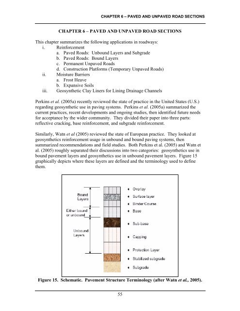
<strong>CHAPTER</strong> 6 – <strong>PAVED</strong> <strong>AND</strong> UN<strong>PAVED</strong> <strong>ROAD</strong> <strong>SECTIONS</strong>(2005) described the practice of combining a paving fabric with chip seal. <strong>This</strong> approachresulted in good performance in desert conditions where temperature changes can bequite large and cracking can be a concern. The first application of fabric with chip sealreported in that study was in 1987, a section that was still performing adequately whenthe paper was written in 2005.Conversely, in a study for the South Dakota DOT, Storsteen and Rumpka (2000) saw nosignificant improvement in reflective crack occurrence or movement when either ageomembrane seal or geogrid was used between asphalt overlays and joints in existingconcrete pavements. <strong>This</strong> study looked at 120 rehabilitated joints and included theapproximate costs of each measure. Based on five years of observations, it wasconcluded that the geogrid used reflected more cracks than the sections with ageomembrane seal or no geosynthetic at all. Storsteen and Rumpka (2000)’s finalrecommendations included a sealed saw cut above the joints without using eithergeosynthetic overlay or extensive rehabilitation at the joint level.Gaps in Our KnowledgeFrom a design standpoint, both Watn et al. (2005) and Perkins et al. (2005a) noted thatno model currently used for design takes into account the wide range of factors that affectthe performance of asphalt pavements. Lytton (1989) proposed a model that included 13different parameters. From Perkins et al.’s (2005a) perspective, the sheer number ofmodel parameters, with their magnitudes likely changing over the length of a roadproject, seems to hinder implementation.Maxim (1997) looked at 200 reports that used geosynthetics in asphalt overlays andsuggested a model for design. Maxim (1997) suggested that the inclusion of ageosynthetics layer corresponded to a reduction in asphalt thickness that ranged from 25to 45 mm (1 to 1-3/4 in). <strong>This</strong> equivalence has also been reported by Carmichael andMarienfeld (1999) and a 15 mm (0.6 in) equivalence by cost was reported by Marienfeldand Smiley (1994). The biggest challenge with citing equivalent thicknesses is that thedesign properties of the geosynthetics, asphalt concrete, the base course, and the subgradeare often not reported alongside the resulting equivalent thickness.While a number of projects are ongoing (for example, NCHRP, 2005), the biggestbarriers to widespread implementation comes mainly from understanding themechanisms of the composite pavement overlay systems. Perkins et al. (2005a) notedthat the causes of success and failure in projects with and without geosynthetics are stilllargely unknown. To that end, they suggested the following: i) determining thegeosynthetic’s primary function for a particular project, ii) understanding and modelingthe entire pavement system with geosynthetics included, iii) creating a user friendlydesign model and, iv) developing a cost analysis to determine whether geosynthetics willbe cost effective over the life cycle of a particular project. It is also imperative to addressthe dire need for systematic field studies to verify the design approaches and modelingresults.62
<strong>CHAPTER</strong> 6 – <strong>PAVED</strong> <strong>AND</strong> UN<strong>PAVED</strong> <strong>ROAD</strong> <strong>SECTIONS</strong>PERMANENT UN<strong>PAVED</strong> <strong>ROAD</strong>SIn some ways, use of geosynthetics to extend the life and improve the performance ofunpaved roadway sections is similar to the unbound section of the paved roads describedearlier. However, current practice tends to treat reinforcement of unpaved roads as aseparate topic from paved road. <strong>This</strong> primarily comes from the lower traffic volume andacceptance of larger ruts that can develop in unpaved road applications.Summary of National GuidelinesAASHTO PP 46-01 (AASHTO 2001) provides guidelines for base course reinforcementby geosynthetics. It recommends following the procedures laid out in Holtz et al. (1998)or the procedures from the GMA White Paper II (Berg et al., 2000). A brief descriptionof both approaches follows.Holtz et al. (1998) consider design methods for permanent applications, where thebearing capacity factor, N c , can be increased to reduce the thickness of any stabilizinglayers, but it is assumed the reinforcement will not improve the structural layers(aggregate base course). No reduction in aggregate base course thickness is allowed.Berg et al. (2000)’s methods are not explicitly applicable to permanent unpaved roads.The methods may eventually be applied if enough field or laboratory data are collectedfor calibration.In the survey, eight of 11 respondents reported being involved in unpaved roadwaydesign, either new construction or rehabilitating of existing roads. When rehabilitatingroadways, six of the eight respondents said they had been involved in a project that alsoused geosynthetics. New construction lagged here, with only two of eight respondentsreporting geosynthetic usage. It would appear then, that unpaved road construction is acommon part of the FLHD work, and that if geosynthetics use in practice can beimproved or updated, potential benefits could be achieved.Level of MaturityDeveloping. While the national design methods do not allow for reduced sections,geosynthetics in unpaved roads are often used in separation and filtration applications toprevent mixing of the base courses with the native soils. In the past two decades, anumber of numerical studies and proposed design methods have been suggested in theliterature for reinforcement applications such that smaller base course layers can bespecified.Recent AdvancesPermanent unpaved road design has appeared often in literature. Early work by Giroudand Noiray (1981) and Steward et al. (1977) proposed design methods that required deepand large rutting magnitudes to mobilize a tensioned membrane effect in the geotextile63
<strong>CHAPTER</strong> 6 – <strong>PAVED</strong> <strong>AND</strong> UN<strong>PAVED</strong> <strong>ROAD</strong> <strong>SECTIONS</strong>layer. Recently, Giroud and Han (2004a and 2004b) proposed a new empirical designmodel for geogrid reinforced unpaved roads, based in part on lab model tests that werereported by Gabr (2001). <strong>This</strong> model accounts for aggregate base course deterioration asthe number of traffic loading cycles increase, and, while developed for a rut depth of 75mm (3 in), allows for the input of different rut depth values, and is calibrated for ageogrid’s aperture stability modulus (ASM). In their closure to the paper (Giroud andHan, 2006), defended the use of ASM, comparing traffic benefit ratios of reinforcedunpaved roads measured by Watts et al. (2004) to 5% secant moduli for the geogridsused. Based on those measurements, it was noted that there was no correlation, that theaverage strains mobilized in the geogrids ranged from 0.1 to 1.2% and ASM is a betterindicator to use in this case.Tingle and Webster (2003) back-calculated bearing capacity factors using results fromfour test sections subjected to simulated traffic loading, observing rut depths up to threeinches. Finite element analysis of unpaved road sections were performed by Perkins etal. (2005b) and Leng and Gabr (2002) and attempted to explain the contribution ofgeosynthetics to increasing the service life of the unpaved section. Leng and Gabr (2005)also presented a design model that estimates the benefits realized in an unpaved sectionwith inclusion of reinforcement. The model includes effect of level of mobilization ofsubgrade bearing capacity as a function of rutting as well as relative aggregate basecourse to subgrade modulus ratio.Gaps in Our KnowledgeThe recent methods proposed by Giroud and Han (2004a and 2004b) are largelyuncalibrated. In their closure (2006) the authors mention that more than 20 paved roaddesigns have since been implemented using their methods. Such database needs to beconsiderably increased, with long term monitoring and model verification for wideacceptance of the proposed approach.The numerical finite element studies reported in literature may be a first step toward amore mechanistic-based design model. These methods, however, are unlikely to maketheir way into common practice unless (i) the interface between user and finite elementmodel are more stream lined and user friendly, (ii) interface and material models areaccepted and (iii) the results are well correlated to measured behavior. So far, the finiteelement studies have provided design charts that are dependent on the type ofreinforcement modeled and the initial boundary conditions assumed.CONSTRUCTION PLATFORMS (TEMPORARY UN<strong>PAVED</strong> <strong>ROAD</strong>S)Temporary unpaved roads have different design requirements than permanent ones.Often times, they are placed simply for construction access, so the rut depths can belarger under lower number of passes by traffic (albeit heavier load). From a FLHDstandpoint, these projects may also be considered within the realm of contractor designbuildarrangement.64
<strong>CHAPTER</strong> 6 – <strong>PAVED</strong> <strong>AND</strong> UN<strong>PAVED</strong> <strong>ROAD</strong> <strong>SECTIONS</strong>Summary of National GuidelinesConstruction platforms are not specifically covered in any national design manual.However, since they are similar to unpaved, temporary roadway reinforcement,AASHTO PP46-01, which references the GMA White Paper II (Berg et al., 2000) andHoltz et al. 1998’s methods may also be used. In the latter, the geosynthetic selected isassumed to allow for reduced thickness of aggregate by improving the drainage andseparation of the soil from the subbase. The model quantifies this effect by allowing ahigher bearing capacity factor, N c . The U.S. Army Corps of Engineers (2003) alsoaddresses unpaved roads in a manner similar to Holtz et al. (1998).Level of MaturityDeveloping. Typically, construction platforms are left to contractors to design. <strong>This</strong>would partially explain the lack of coverage in the national literature, and the low number(one) of survey respondents who said they were involved in construction platform designor construction.Recent AdvancesTemporary work platforms are sometimes constructed over soft or very wet soils usinggranular fills and geosynthetics to avoid rutting and mud waves due to constructiontraffic. Currently, design of these platforms is based on local bearing capacityconsiderations, where geosynthetics tend to increase the bearing capacity factor and alsoattenuate the stresses transferred to the subgrade. The configuration may call for a 3Dstability solution but is normally treated with a 2D plane strain model for simplicity.Often only one layer of geosynthetics is used. Perkins et al. (2005a) noted subgradereinforcement for construction platforms is quite common, and usually implemented by aconstruction team.The methods used to design unpaved roads can also be used for construction platforms.In this case, geosynthetics are used at an interface between soft soils and an aggregatesubbase (or other granular fill). Giroud and Noiray (1981) and Steward et al. (1977)proposed design methods for these situations that assume the rut depth is deep enough fora tensioned membrane effect to develop in the reinforcement layer. Similarly, Leong etal.(2000) performed bench scale models of roadways using anchored and pretensionedgeotextiles and reported the response of the composite section.Giroud and Han (2004a and 2004b)’s empirical design model for geogrid reinforcedroadways could also be used for construction platforms. In this application, the allowablerut depth should perhaps be larger and number of traffic passes should be decreased, butwith heavier truck load, to account for the temporary nature of construction loading.65
<strong>CHAPTER</strong> 6 – <strong>PAVED</strong> <strong>AND</strong> UN<strong>PAVED</strong> <strong>ROAD</strong> <strong>SECTIONS</strong>Gaps in Our KnowledgeFuture design methodologies should consider multiple layers of geosynthetics and theirimpact on reducing the thickness of the aggregate base course (ABC)m as well aslimiting it deterioration with cyclic loading. Similarly, development of 3-D models suchas those described by Perkins et al. (2005b) may lead to more refined results, particularlyif very heavy construction loads are involved.A wider survey of methods used by contractors on federal lands projects may also lead toa better understanding of their practice and the ability t o suggest improvements.Alternatively, more careful monitoring of the performance of temporary roadways andplatforms on new projects could lead to a larger data and experience base. <strong>This</strong> couldimprove the confidence of construction, inspection and design personnel, and lead toimproving current design methods and avoiding experiences like that reported by asurvey respondent’s in Chapter 3.MOISTURE BARRIERSThe use of geotextiles (typically thick nonwoven needle-punched) as a capillary break issummarized by Koerner (1998). The fabric’s in-plane drainage capacity acts to cut downon the tendency of water to rise above the water table due to capillary action. If the sizeof the pore spaces are abruptly increased, the pore water will then tend to flow in-plane,and can be removed by underdrains. <strong>This</strong> behavior is helpful for mitigating volumechanges due to ice lenses in cold weather and for stopping salt water rise in very aridregions.Another commonly used moisture barrier, primarily in Texas and throughout the west,are geomembranes to prevent water infiltration. In these cases, water from roadwayscomes in contact with layers of expansive soils in the subgrade. <strong>This</strong> causes roadwayheave and significantly degrades the pavement structure.Summary of National GuidelinesThere are currently no existing national guidelines for design of capillary barriers tomitigate frost heave. The Geosynthetics manual (Holtz, 1998) does not mention theiruse. In the survey of FLHD and USFS engineers, one noted capillary barrier projects,and six noted they were involved in frost heave projects. Three of the six reportedinvolvement with geosynthetics. Based on that small sample, there appears to be somedemand for frost heave mitigation, and some interest in geosynthetics usage as moistureor capillary barriers. For prevention of water infiltration into expansive soils, few nationalguidelines are included. However, the Geosynthetics Manual (Holtz, 1998) does considergeomembranes in other barrier applications, such as landfills and containment units.66
<strong>CHAPTER</strong> 6 – <strong>PAVED</strong> <strong>AND</strong> UN<strong>PAVED</strong> <strong>ROAD</strong> <strong>SECTIONS</strong>surfaces in different sections. Other methods used included edge drains or geotextilewrappedgravel layers 0.3 m (1 ft) beneath the pavement surface to improve drainageduring thaws. Henry et al. (2005) concluded that performance of the roadways were bestin the sections that either provided additional strength throughout the profile (the Geocelland the cement sections), or that provided better vertical drainage and moisture controlprior to freezing (the capillary barriers or the geotextile-wrapped gravel layers). Theedge drains were thought to not be effective due to the relatively slow lateral drainage ofwater from the center of the roadway to the edges. It was also concluded that thegeotextile separator and geogrid reinforcement did little to improve the upper 75 to 300mm (3 to 12 in) of the roadway, which was saturated during the spring thaw and thenmost susceptible to deep rutting failures.Other studies have investigated the use of polystyrene sheets as insulators (Kestler andBerg, 1995 and Konrad et al., 1996). In this case, the polystyrene inclusion acts tointerrupt the formation of ice, reducing the zone where heave can occur. Similarly, Leuand Tasa (2001) discuss practices in Minnesota, where geotextiles have been usedprimarily for their ability to separate sections damaged by frost boil (where fine subbasematerial is pushed up into the aggregate base course during thaws) from the newly placedsubgrade.Recent Advances—Barriers for Expansive SoilsSteinberg (1998) describes in detail a number of highway and structural case studies fromthe American West and around the world that have used Geosynthetics to mitigateexpansive soil problems. A discussion of testing, design and material costs is alsopresented. Basically, the geomembrane is installed as a barrier against vertical waterinfiltration, against horizontal water infiltration from road shoulders or other flowingground water, or against both. The geomembrane placed has very low hydraulicconductivity, which essentially keeps the initial moisture in the expansive soilunchanged. These horizontal and vertical barriers are usually installed in tandem withdrainage structures, to prevent water from ponding on the road surface and to reducehydraulic heads leading to water infiltration.Gaps in Our KnowledgeThe largest gaps in frost heave mitigation practice involve applying the results of therelatively few laboratory and field tests to model development and practice. There isongoing work as to the best methods to mitigate frost heave. While geosyntheticcapillary barriers are gaining some ground as a new application, specific design methodsand field performance data have yet to be developed.More controlled field testing will be required to fully quantify whether certain frost heavemitigation techniques, either as moisture barrier, capillary barrier, or both, are useful.These types of studies, however, require multi-year commitments to monitoring over aseries of freeze-thaw seasonal cycles. A viable design method is also required, as aremethods that will allow the costs of various possible solutions to be compared. In68
<strong>CHAPTER</strong> 6 – <strong>PAVED</strong> <strong>AND</strong> UN<strong>PAVED</strong> <strong>ROAD</strong> <strong>SECTIONS</strong>expansive soils, most solutions appear to be regional or on a state-by-state basis. A moresystematic national effort and design methodologies is needed for wider application ofthis technology.GEOSYNTHETIC CLAY LINERSGeocomposite Clay Liners (GCLs) are manufactured by sandwiching or embeddingbentonite clay in geotextiles or attaching a layer of bentonite to geomembranes. As watercomes in contact with the bentonite, the bentonite expands, effectively reducing thehydraulic conductivity and creating a barrier to flow. For drainage ditches, the GCLcould be used to minimize seepage into the surrounding ground, and channeling the waterto a sump area for routing to storm water facilities. GCLs can also be a key componentin reducing contaminant transport from roadways into the surrounding environment,allowing non-point source contaminated run-off to be sent to a particular location fortreatment instead of making its way directly into sensitive areas.Summary of National GuidelinesGCLs are mentioned briefly in the “barriers” section of the NHI Geosynthetics manual(Holtz et al. 1998). In that section, their usage was described as waterproofing layers intunnels walls or bridge abutments, storm water retention pond or canal liners, andsecondary containment for underground storage tanks. It is also mentioned thatoverlapping is generally required to create a water-tight seal.Level of MaturityUnderdeveloped. While GCLs for environmental applications (such as landfills) arewell developed, the application to prevent seepage from ditches are virtually unused bythe FLH. Only one of eleven respondents in the survey in Chapter 3 reported usinggeosynthetic clay liners in any application. <strong>This</strong> may be partly due to unfamiliarity withthe material, concerns about long term performance, or a lack of more explicit guidancein design documents.Recent AdvancesBoardman and Daniel (1996) investigated the ability of clay liners to “self heal” overmany wetting and drying cycles in two geotextile-bentonite (GT-B) composites. Theynoted that one GT-B system developed large cracks in the bentonite when desiccated,which significantly increased hydraulic conductivity (from 10 -9 to 10 -3 cm/s or fromapproximately 10 -10 to 10 -4 in/s in this study) until the bentonite was rehydrated. In thistest, hydration took a little over an hour. The other GT-B system did not develop suchcracks during desiccation, an observation attributed to the higher reinforcement given bythe particular geotextile used in the product. Lin and Benson (2000) performed a similartest, adding a calcium chloride solution and more wetting-drying cycles. They, tooobserved significant cracking and loss of self-healing due to the chemical change in thebentonite and the loss of its ability to self heal.69
<strong>CHAPTER</strong> 6 – <strong>PAVED</strong> <strong>AND</strong> UN<strong>PAVED</strong> <strong>ROAD</strong> <strong>SECTIONS</strong>Egloffstein (2001) noted that hydraulic conductivity of GCL liners tends to increase overthe first three years of the liners’ life, as sodium ions in the bentonite are replaced bycalcium ions in the seepage liquid. <strong>This</strong> ion replacement can increase the hydraulicconductivity by as much as one order of magnitude. In ditches near roadways or otherstructures to which deicing salts, such as calcium chloride, are applied this ion exchangecould be of concern and would have to be considered in design. Jo et al. (2005) furtherobserved the stronger the salt solution, the more likely an increase in hydraulicconductivity. Jo also noted the amount of time it took for GCLs exposed to salt solutionsto reach a stable, higher conductivity. For weak salt solutions (< 50 mM calcium ion), anincrease of around one order of magnitude in hydraulic conductivity occurred over a timeperiod of about 0.2 years. For stronger solutions, Jo et al. (2005) observed a nearlyimmediate 3 order of magnitude increase in hydraulic conductivity that stayed constantthereafter.GCL liners for canal rehabilitation in Germany were reported by Heerten and List (1990).Side slopes varied from 5 to 30 degrees, and the measured shear strength was 34 degrees,which was in part dictated by the nonwoven needling process. In this case, a soil coverwas used over the GCL. Crouse et al. (2000) described procedures used to install GCL’sat a mine site. The GCL was covered with rock using a scraper and belly dump. Afterinstallation and removal of the rock, visual inspection showed no observable damage tothe GCL by either the rocks or the scraper.The required overlap of GCL to overcome possible shrinkage and separation betweenadjoining layers was discussed by Thiel et al. (2005). They measured shrinkage due tocyclic wetting and drying and recommended overlap amounts to overcome the change inGCL panel spacing. On a related material note, Zornberg et al. (2005) compiled adatabase of direct shear tests on GCL to measure the GCL’s internal friction angle. Theydetermined the internal friction shear strength of a GCL varies considerably betweenmanufacturers and the date of manufacture, and includes variability in the type ofgeosynthetic used and the bentonite used.Gaps in Our KnowledgeThe research above identifies a few areas of inquiries, mainly considering the behavior ofthe GCLs. First, the change in hydraulic conductivity over time due to wetting anddrying cycles, desiccation and salt infiltration should be better quantified. The hydraulicconductivity value will determine how much water seeps from the ditch. Second, shearstrength and overlap considerations will determine survivability and constructability ofthe GCL liner system. These values will have to be combined with other studies of soil-GCL interface friction studies, either on the manufacturer level or on a project basis.Third is the behavior of GCL under relatively thin cover thickness as would be the casefor lining ditches.The biggest barrier however to wider GCL implementation is the increase in hydraulicconductivity that appears to occur when the bentonite comes in contact with salt70
<strong>CHAPTER</strong> 6 – <strong>PAVED</strong> <strong>AND</strong> UN<strong>PAVED</strong> <strong>ROAD</strong> <strong>SECTIONS</strong>solutions, resulting in cracks that will not fully self heal after desiccation due to the lossof swelling. Unless the GCL can survive such environmental hazards or the location ischosen such that the GCL remains at least partially wet or away from road or natural saltinfiltration, increases in seepage will occur.Part of the problem may be solved by using expansive clays with more calcium thansodium. While this would decrease some of the swell potential, it would reduce the ionexchange that occurs when sodium-rich bentonite is exposed to high concentrations ofcalcium in solution. Lee and Shackelford (2005) observed similar behavior in their work,where bentonite with higher calcium content did not show increases in hydraulicconductivity as large as higher sodium content bentonite when exposed to calciumchloride solution.SUMMARY<strong>This</strong> chapter reviewed the progress of geosynthetics as applied to pavements, includingreinforcement applications, moisture barriers and geosynthetic clay liners for liningditches. In spite of the length of time geosynthetics have been used in pavementapplications, there is still a lack of consensus as to their benefits. There is, however, atremendous opportunity for future development and optimization of usage to determinethe cost-effectiveness of geosynthetic in new and rehabilitation applications as describedin this chapter. In the meantime, it seems the most benefit can be derived by FLHD fromsystematic and careful application of geosynthetics to particular projects, monitoringperformance, and focusing not only on the benefits realized but also understanding thelikely reasons for those benefits. These calibration efforts should be a part of the largerefforts underway by NCHRP and FHWA to develop new and refine existing designmethods.Reinforcement applications are by far the most common use of geosynthetics in pavedroads, unpaved roads or construction platforms. Despite decades of laboratory and fieldscale testing, the available design procedures (particularly for unpaved roadways) stillrecommend significant field verification efforts if geosynthetics are used as part of adesign. Mechanistic-empirical design methods are currently being developed for pavedroadway design, as are comparative ways to determine the cost effectiveness of roadwayprofiles containing geosynthetics. These continuing developments should be monitoredin coming few years to see if wider implementation is possible.Moisture and capillary barriers have been implemented and studied more frequently, andare a developing technology. The use of geosynthetics to control expansive soils hasmainly focused on encapsulation of the soils beneath the roadway with geosynthetics,while control of frost heave has focused on adding drainage layers or capillary barriers toprevent water from freezing in the roadway profile. On the other hand, geosynthetic clayliners run-off control are largely undeveloped for roadway applications. Further studiesof their survivability and effectiveness on a field scale must be performed before theycould be widely implemented and accepted in practice.71