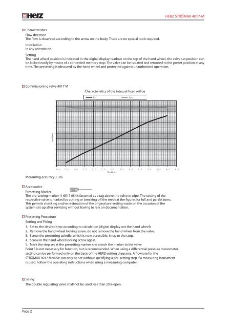
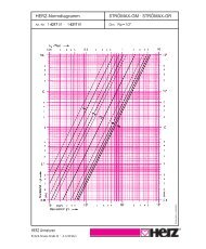
<strong>HERZ</strong> STRÖMAX <strong>4017</strong>-MCharacteristicsFlow directionThe flow is observed according to the arrow on the body. There are no special tools required.InstallationIn any orientation.SettingThe hand wheel position is indicated in the digital display readout on the top of the hand wheel, the valve set position canbe locked easily by means of a concealed memory stop. The valve can be isolated and returned to the preset position at anytime. The presetting is obscured by the hand wheel and protected against unauthorized operation.Commissioning valve <strong>4017</strong> MCharacteristics of the integral fixed orificekv-Wert Ventil gesamtkv-Wert kvs Blendekv kv-W values ertMeasuring accuracy ± 3%0,0 0,5 1,0 1,5 2,0 2,5 3,0 3,5 4,0 4,5 5,0 5,5 6,0 6,5Position VoreinstellstufeAccessoriesPresetting MarkerThe pre-setting marker (1 6517 05) is fastened as a tag above the valve or pipe. The setting of therespective valve is marked by cutting or breaking off the teeth at the figures for full and partial turns.This permits checking and/or restoration of the original pre-setting made on the occasion of thesystem set-up after servicing without having to rely on documentation.Presetting ProcedureSetting and Fixing1. Set to the desired step according to calculation (digital display ont the hand wheel).2. Remove the hand wheel locking screw, do not remove the hand wheel from the valve.3. Screw the presetting spindle, which is now accessible, in up to the stop.4. Screw in the hand wheel locking screw again.5. Mark the step set at the presetting marker and attach the marker to the valvePoint 5 is not necessary for function, but is recommended. When using a differential pressure manometer,setting can be performed only on the basis of the <strong>HERZ</strong>-setting diagrams. A flowrate for theSTRÖMAX <strong>4017</strong> M valve can only be set without specifying a pre-setting step if a measuring instrumentis used. Follow the operating instructions when using a measuring computer.SizingThe double regulating valve shall not be used less than 25% open.Page 2
<strong>HERZ</strong> STRÖMAX <strong>4017</strong>-M<strong>HERZ</strong> connection adapters for copper and steel pipesThe commissioning valves can optionally be connected to a threaded pipe or used on a calibrated copper pipe compressionadapter. Compression adapters must be ordered separately.Pipe dimension mm 8 10 12 14 15 16 18Valve DN 15Adapter 1 6266 01 1 6266 01 1 6266 01 1 6266 01 1 6266 01 1 6266 01 1 6266 01connection adapter 1 6274 18 1 6274 00 1 6274 01 1 6274 02 1 6274 03 1 6274 04 –connection adapter – – 1 6276 12 1 6276 14 1 6276 15 1 6276 16 1 6276 18Pipe dimension mm 8 10 12 14 15 16 18 22Valve DN 20Adapter 1 6266 20 1 6266 20 1 6266 20 1 6266 20 1 6266 20 1 6266 20 1 6266 20 1 6266 13connection adapter 1 6274 18 1 6274 00 1 6274 01 1 6274 02 1 6274 03 1 6274 04 – 1 6273 01connection adapter – – 1 6276 12 1 6276 14 1 6276 15 1 6276 16 1 6276 18 –Pipe dimension mm 22Valve DN 25Adapter 1 6266 03connention adapter 1 6273 01When installing soft steel or copper pipes with a pipe wall of 1 mm or less with compression unions, we recommend the useof support sleeves (order no.: 1 0674 xx). When installing plastic pipes, suitable calibration tools are needed. Please refer toour instruction manual. For proper installation use silicone oil to lubricate the thread of the locking nut or olive screw as wellas the olive.Plastic pipe connectionsThe commissioning valves can be used in systems with plastic pipes. Plastic pipe connections are fitted to special adapters.Pipe dimension mm 14 x 2 16 x 2 16 x 2,2 17 x 2 17 x 2,5 18 x 2 18 x 2,5 20 x 2 20 x 2,5 20 x 3,5Valve DN 15Adapter 1 6266 01 1 6266 01 1 6266 01 1 6266 01 1 6266 01 1 6266 01 1 6266 01 1 6266 01 1 6266 01 1 6266 01Pipe connection 1 6098 02 1 6098 03 1 6098 12 1 6098 04 1 6098 05 1 6098 07 1 6098 06 1 6098 08 1 6098 11 1 6098 10Pipe dimension mm 14 x 2 16 x 2 16 x 2,2 17 x 2 17 x 2,5 18 x 2 18 x 2,5 20 x 2 20 x 2,5 20 x 3,5Valve DN 20Adapter 1 6266 20 1 6266 20 1 6266 20 1 6266 20 1 6266 20 1 6266 20 1 6266 20 1 6266 20 1 6266 20 1 6266 20Pipe connection 1 6098 02 1 6098 03 1 6098 12 1 6098 04 1 6098 05 1 6098 07 1 6098 06 1 6098 08 1 6098 11 1 6098 10Pipe dimension mm 16 x 2 20 x 2 25 x 3,5 26 x 3Valve DN 25Adapter 1 6266 03 1 6266 03 1 6266 03 1 6266 03Pipe connection 1 6098 11 1 6098 12 1 6198 00 1 6198 01Spare parts 1 0284 01 1/4 test point for <strong>HERZ</strong> circuit control valve, blue cap (return)1 0284 02 1/4 test point for <strong>HERZ</strong> circuit control valve, red cap (flow)2 0284 01 1/4 test point for <strong>HERZ</strong> circuit control valve (for drinking water), blue cap (return)2 0284 02 1/4 test point for <strong>HERZ</strong> circuit control valve (for drinking water), red cap (flow)1 0284 11 1/4 test point for <strong>HERZ</strong> circuit control valve, extended model, blue cap (return)1 0284 12 1/4 test point for <strong>HERZ</strong> circuit control valve, extended model, red cap (flow)1 0284 22 1/4 <strong>HERZ</strong> test point with draining function, red cap (flow)1 0284 21 1/4 <strong>HERZ</strong> test point with draining function, blue cap (return)Page 3