Specification for Electrical works – 2009 (in PDF format,Size: 6.4MB)
Specification for Electrical works – 2009 (in PDF format,Size: 6.4MB)
Specification for Electrical works – 2009 (in PDF format,Size: 6.4MB)
- No tags were found...

You also want an ePaper? Increase the reach of your titles
YUMPU automatically turns print PDFs into web optimized ePapers that Google loves.
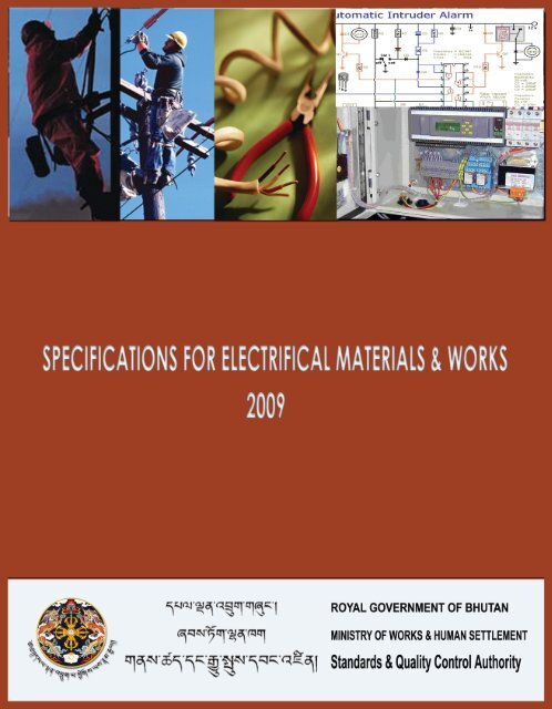
MINISTRY OF WORKS AND HUMAN SETTLEMENTSTANDARDS AND QUALITY CONTROL AUTHORITYSPECIFICATIONS FOR ELECTRICAL MATERIALS AND WORKS<strong>2009</strong>
DisclaimerThe BSR (both Civil and <strong>Electrical</strong>)‐ <strong>2009</strong> is prepared and published primarily as a toolto assist <strong>in</strong> the estimation of project costs. Due to difficulty <strong>in</strong> obta<strong>in</strong><strong>in</strong>gcomprehensive and accurate rates from base towns, and the associated complexity <strong>in</strong>their analysis, the BSR reflects only suggestive averages and not accurate currentmarket rates. Material and labour rates also fluctuate frequently, and by the time ofthe publication of this book, many rates would have already changed. Hence users areadvised to refra<strong>in</strong> from us<strong>in</strong>g the BSR <strong>for</strong> the purposes of fill<strong>in</strong>g tenders, evaluat<strong>in</strong>gtenders, award<strong>in</strong>g <strong>works</strong> and/or mak<strong>in</strong>g contractual payments. The publisher is <strong>in</strong> noway accountable or answerable <strong>for</strong> any issues/disputes aris<strong>in</strong>g as a result of<strong>in</strong>dividuals or agencies us<strong>in</strong>g the rates <strong>in</strong> the BSR‐<strong>2009</strong> as a basis <strong>for</strong> fill<strong>in</strong>g theirtenders, evaluat<strong>in</strong>g tenders, award<strong>in</strong>g <strong>works</strong> and/or mak<strong>in</strong>g contractual payments.©All rights reserved with SQCA, MoWHS. Reproduction <strong>for</strong> sale of this publication, <strong>in</strong> part(s) orwhole, <strong>in</strong> any <strong>for</strong>m or by any means, by any agency or <strong>in</strong>dividual, is a punishable offence and isstrictly prohibited.
[Year]<strong>Specification</strong>s <strong>for</strong> <strong>Electrical</strong> Materials and Works <strong>2009</strong>Table of Contents1‐ ABBREVIATIONS............................................................................................................................ 52‐ DEFINITIONS ................................................................................................................................. 63‐ GENERAL ......................................................................................................................................... 103.1.1 Draw<strong>in</strong>gs .......................................................................................................................... 103.1.2 Materials .......................................................................................................................... 103.1.3 Workmanship ................................................................................................................... 103.1.4 Rat<strong>in</strong>gs of electrical components ..................................................................................... 113.1.5 Structural alteration to build<strong>in</strong>gs ..................................................................................... 113.1.6 Work <strong>in</strong> occupied build<strong>in</strong>gs .............................................................................................. 113.1.7 Test<strong>in</strong>g and commission<strong>in</strong>g on completion ..................................................................... 113.1.8 Additional load to an exist<strong>in</strong>g Installation ....................................................................... 113.1.9 Connection to ancillary build<strong>in</strong>gs ..................................................................................... 124‐ WIRING SYSTEM ............................................................................................................................. 134.1 PVC Cas<strong>in</strong>g and Capp<strong>in</strong>g ...................................................................................................... 134.1.1 Fix<strong>in</strong>g cas<strong>in</strong>g‐capp<strong>in</strong>g ................................................................................................... 134.1.2 Provid<strong>in</strong>g earth cont<strong>in</strong>uity wires .................................................................................. 144.1.3 <strong>Size</strong> and Measurement ................................................................................................. 144.2 Conduit Wir<strong>in</strong>g ..................................................................................................................... 164.2.1 PVC Conduits/HDPE Pipes ................................................................................................ 194.2.1.1 Surface ...................................................................................................................... 194.2.1.2 Concealed .................................................................................................................. 194.2.1.3 Provid<strong>in</strong>g Earth Cont<strong>in</strong>uity Wires .............................................................................. 204.2.1.4 PVC conduit size ........................................................................................................ 204.2.2 MS Conduits ..................................................................................................................... 204.2.2.1 Surface ...................................................................................................................... 204.2.2.2 Concealed .................................................................................................................. 214.2.2.3 Provid<strong>in</strong>g Earth Cont<strong>in</strong>uity Wires .............................................................................. 214.2.2.4 Conduit size and Measurement ................................................................................ 214.2.3 Steel Conduits ................................................................................................................. 224.2.3.1 Surface ...................................................................................................................... 224.2.3.2 Provid<strong>in</strong>g Earth Cont<strong>in</strong>uity Wires .............................................................................. 224.2.3.3 Conduit size and measurement ................................................................................ 225‐ INTERNAL WIRING PRACTICES ....................................................................................................... 235.1 Circuit wir<strong>in</strong>g ........................................................................................................................ 235.2 Sub‐ma<strong>in</strong> wir<strong>in</strong>g ................................................................................................................... 235.3 Power distribution ma<strong>in</strong>s wir<strong>in</strong>g ......................................................................................... 235.4 System of wir<strong>in</strong>g and loads .................................................................................................. 235.5 Jo<strong>in</strong>ts & loop<strong>in</strong>g back ........................................................................................................... 245.6 Pass<strong>in</strong>g through wall ............................................................................................................ 245.7 Pass<strong>in</strong>g through floor ........................................................................................................... 245.8 Bunch<strong>in</strong>g of Cables .............................................................................................................. 246‐ POINT WIRING ................................................................................................................................ 256.1 Measurement of po<strong>in</strong>t wir<strong>in</strong>g .............................................................................................. 25Standards & Quality Control Authority, MoWHS Page 1
[Year]<strong>Specification</strong>s <strong>for</strong> <strong>Electrical</strong> Materials and Works <strong>2009</strong>7‐ BOXES (SURFACE/RECESSED) ......................................................................................................... 267.1 Wooden, PVC and Steel boxes ............................................................................................ 267.2 MS Boxes ............................................................................................................................. 268‐ FITTINGS, ACCESSORIES AND APPLIANCES .................................................................................... 278.1 Fitt<strong>in</strong>gs ................................................................................................................................. 278.2 Lamps ................................................................................................................................... 278.3 Lum<strong>in</strong>aries ........................................................................................................................... 308.3.1 Indoor Lum<strong>in</strong>aries ................................................................................................................. 308.3.1.1 Home light<strong>in</strong>g Lum<strong>in</strong>aries ......................................................................................... 308.3.1.2 Lum<strong>in</strong>aries <strong>for</strong> Commercial areas ............................................................................. 308.3.1.3 Lum<strong>in</strong>aries <strong>for</strong> decorative and accent light<strong>in</strong>g ......................................................... 318.3.1.4 Lum<strong>in</strong>aries <strong>for</strong> Industries uses .................................................................................. 328.3.1.5 Bulkhead lum<strong>in</strong>aries ................................................................................................. 328.3.1.6 Indoor <strong>in</strong>dustrial well glass lum<strong>in</strong>aries ..................................................................... 328.3.1.7 Lum<strong>in</strong>aries <strong>for</strong> hazardous areas ............................................................................... 338.3.2 Outdoor Lum<strong>in</strong>aries ......................................................................................................... 338.3.2.1 Public light<strong>in</strong>g lum<strong>in</strong>aries.......................................................................................... 338.3.2.2 Lum<strong>in</strong>aries <strong>for</strong> Environment light<strong>in</strong>g ........................................................................ 348.3.2.3 Floodlight<strong>in</strong>g Lum<strong>in</strong>aries .......................................................................................... 348.4 Accessories .............................................................................................................................. 348.4.1 Switches ........................................................................................................................... 348.4.2 Lamp Holders ................................................................................................................... 358.4.3 Ceil<strong>in</strong>g Rose ...................................................................................................................... 358.4.4 Socket Outlets .................................................................................................................. 358.4.5 Socket outlet <strong>for</strong> call bell ................................................................................................. 368.4.6 Socket outlet <strong>for</strong> telephone ............................................................................................. 368.4.7 Attachment of fitt<strong>in</strong>gs and accessories ........................................................................... 368.5.1 Ceil<strong>in</strong>g Fans ...................................................................................................................... 378.5.2 Exhaust Fans ..................................................................................................................... 398.5.3 Fan Regulators ................................................................................................................. 398.5.4 Immersion Water Heater and Geyser .............................................................................. 398.5.5 Electric Stove .................................................................................................................... 408.5.6 Room Heater .................................................................................................................... 408.5.7 Air Cooler and Refrigerator .............................................................................................. 408.5.8 Electric iron, rice/curry cooker and water boiler vacuum cleaner, drier, iron, mixture 419‐ CABLES ............................................................................................................................................ 429.1 Cable Types and Classification ............................................................................................. 429.2 Cable <strong>Size</strong> Selection ............................................................................................................. 439.3 Cable Storage and Handl<strong>in</strong>g ................................................................................................ 439.4 Cable Installation ................................................................................................................. 449.5 Cable Lay<strong>in</strong>g ......................................................................................................................... 449.5.1 Directly buried .................................................................................................................. 449.5.2 Lay<strong>in</strong>g <strong>in</strong> pipe ................................................................................................................... 459.5.3 Lay<strong>in</strong>g <strong>in</strong> closed duct or trench ........................................................................................ 459.5.4 Lay<strong>in</strong>g on surface or open duct ........................................................................................ 459.6 Cable Term<strong>in</strong>ation & Jo<strong>in</strong>t<strong>in</strong>g .............................................................................................. 4510‐ CONTROL GEARS .......................................................................................................................... 48Standards & Quality Control Authority, MoWHS Page 2
[Year]<strong>Specification</strong>s <strong>for</strong> <strong>Electrical</strong> Materials and Works <strong>2009</strong>10.1 Ma<strong>in</strong> Switchgears, Switchboard and their Location ........................................................ 4810.2 Types of Switchboards ..................................................................................................... 4910.2.1 H<strong>in</strong>ged Type Metal Boards .............................................................................................. 4910.2.2 Fixed Type Metal Boards ................................................................................................. 4910.3 Mark<strong>in</strong>g of Apparatus ...................................................................................................... 5010.4 Ma<strong>in</strong> and Branch Distribution Boards and their Location ............................................... 5010.5 Control at Po<strong>in</strong>t of Entry of Supply .................................................................................. 5110.6 Bus‐Bars and Bus‐Bar chambers ...................................................................................... 5210.6.1 Bus Bar Chambers ........................................................................................................... 5210.6.2 Bus Bars ........................................................................................................................... 5210.6.3 Bus‐Bar Supports and Attachments ................................................................................ 5210.6.3.1 Supports .................................................................................................................... 5210.6.3.2 Connections to Bus Bars ........................................................................................... 5310.6.3.3 Clearances ................................................................................................................. 5310.6.4 Bus Bar Mark<strong>in</strong>gs............................................................................................................. 5310.6.4.1 The colours and letters (or symbols) <strong>for</strong> bus bars ..................................................... 5310.6.4.2 Phase sequence and polarity .................................................................................... 5410.7 Arrangement of Bus Bars and Ma<strong>in</strong> Connections ............................................................ 5410.7.1 A.C. System .................................................................................................................. 5410.7.2 D.C. System .................................................................................................................. 5511‐ COMPOUND/STREET LIGHTING WORK ........................................................................................ 5611.1 Outdoor Fitt<strong>in</strong>gs ............................................................................................................... 5611.2 Steel Tubular Poles ........................................................................................................... 5612‐ EARTHING ..................................................................................................................................... 5712.1 Types of Earth Electrodes ................................................................................................ 5712.2 Selection of Earth Electrode ............................................................................................ 5712.3 Arrangement <strong>for</strong> Earthed Electrode ................................................................................ 5712.3.1 Pipe Earth Electrode ..................................................................................................... 5712.3.2 Plate Earth Electrode .................................................................................................... 5712.3.3 Strip or Conductor Electrode ........................................................................................ 6012.4 Method of Install<strong>in</strong>g Water<strong>in</strong>g Arrangement .................................................................. 6012.5 Location <strong>for</strong> Earth Electrode ............................................................................................ 6012.6 Artificial Treatment of Soil ............................................................................................... 6012.7 Number of Earth Electrodes <strong>for</strong> Installation .................................................................... 6112.8 Resistance of Earth .......................................................................................................... 6112.9 <strong>Size</strong> of Earth<strong>in</strong>g Lead ........................................................................................................ 6112.9.1 Ma<strong>in</strong> earth<strong>in</strong>g Lead ...................................................................................................... 6112.9.2 <strong>Size</strong> of Earth Lead <strong>for</strong> Substations/Generat<strong>in</strong>g Stations .............................................. 6112.9.3 <strong>Size</strong> of Earth Cont<strong>in</strong>uity Conductor ............................................................................... 6212.10 Method of Connect<strong>in</strong>g Earth Lead to Earth Electrode .................................................... 6212.11 Protection of Earth<strong>in</strong>g Lead ............................................................................................. 6213‐ PAINTING ...................................................................................................................................... 6313.1 Preparation of the surface ............................................................................................... 6313.2 Application ....................................................................................................................... 6313.3 Scope ................................................................................................................................ 6313.4 Pa<strong>in</strong>t<strong>in</strong>g of Conduit and Accessories ................................................................................ 6314‐ TESTING OF INSTALLATION .......................................................................................................... 64Standards & Quality Control Authority, MoWHS Page 3
[Year]<strong>Specification</strong>s <strong>for</strong> <strong>Electrical</strong> Materials and Works <strong>2009</strong>14.1 Insulation Resistance Test ................................................................................................ 6414.2 Polarity Test of Switch ..................................................................................................... 6514.3 Earth Cont<strong>in</strong>uity Test ....................................................................................................... 6514.4 Measurement of Earth Electrode Resistance .................................................................. 6515‐ PROTECTION OF BUILDING AGAINST LIGHTNING ........................................................................ 6715.1 Pr<strong>in</strong>ciple of Protection ..................................................................................................... 6715.2 Zone of Protection ........................................................................................................... 6715.3 Materials and Dimensions ............................................................................................... 6715.4 Design Considerations ..................................................................................................... 6915.5 Down Conductors ............................................................................................................ 6915.6 Jo<strong>in</strong>ts and Bonds .............................................................................................................. 7015.7 Fasteners .......................................................................................................................... 7015.8 Earth Term<strong>in</strong>ations .......................................................................................................... 7015.9 Earth Electrode ................................................................................................................ 7016‐ SAFETY PROCEDURE ..................................................................................................................... 71Standards & Quality Control Authority, MoWHS Page 4
[Year]<strong>Specification</strong>s <strong>for</strong> <strong>Electrical</strong> Materials and Works <strong>2009</strong>1‐ ABBREVIATIONSThe follow<strong>in</strong>g abbreviations wherever they appear <strong>in</strong> the specifications shall have the mean<strong>in</strong>gor implication hereby assigned to them.A : AmpereA.C : Alternat<strong>in</strong>g CurrentC.I : Cast IronCFLs : Compact Fluorescent LampsDB : Distribution BoardD.C : Direct CurrentELCB : Earth Leakage Circuit BreakerG.I : Galvanized IronGLS : General Light<strong>in</strong>g ServiceHF : High FrequencyHID : High Intensity DischargeHRC : High Ruptur<strong>in</strong>g CapacityHT : High TensionI : CurrentICDB : Iron Clad Distribution BoardKV : Kilo VoltKW : Kilo WattLT : Low TensionMCB : M<strong>in</strong>iature Circuit BreakerMS : Mild SteelPVC : Polyv<strong>in</strong>yl ChlorideR : ResistanceRCCB : Residual Current Circuit BreakerSDB : Sub Distribution BoardSPMCB : S<strong>in</strong>gle Pole M<strong>in</strong>iature Circuit BreakerSPN : S<strong>in</strong>gle Pole & NeutralTPN : Triple Pole & NeutralV : VoltW : WattStandards & Quality Control Authority, MoWHS Page 5
[Year]<strong>Specification</strong>s <strong>for</strong> <strong>Electrical</strong> Materials and Works <strong>2009</strong>2‐ DEFINITIONSThe def<strong>in</strong>itions given below shall be applicable to all sections unless otherwise <strong>in</strong>dicated.2.1 Accent light<strong>in</strong>g: Directional light<strong>in</strong>g to emphasize a particular object or draw attention to apart of the field of view.2.2 Alum<strong>in</strong>ium conductor steel re<strong>in</strong><strong>for</strong>ced: In Alum<strong>in</strong>ium conductor steel re<strong>in</strong><strong>for</strong>cedconductor, alum<strong>in</strong>ium wires surround a core consist<strong>in</strong>g of one or more steel wires.2.3 Arrester: A non‐l<strong>in</strong>ear device to limit the amplitude of voltage on a power l<strong>in</strong>e. The termimplies that the device stops over voltage problems (i.e. light<strong>in</strong>g).2.4 Armour<strong>in</strong>g: : It consists of one or two layers of galvanized steel wire or steel tape, toprotect the cable from mechanical <strong>in</strong>jury while lay<strong>in</strong>g it and dur<strong>in</strong>g the course of handl<strong>in</strong>g2.5 Alternat<strong>in</strong>g current: The term alternat<strong>in</strong>g current refers to a current that reverses atregular recurr<strong>in</strong>g <strong>in</strong>tervals of time and that has alternately positive and negative values.2.6 Arc<strong>in</strong>g contacts (arc<strong>in</strong>g horns): Arc<strong>in</strong>g contacts are the contacts on which the arc is drawnafter the ma<strong>in</strong> contacts of a switch have parted.2.7 Bond<strong>in</strong>g jumper: A bare or <strong>in</strong>sulated conductor used to ensure the required electricalconductivity between metal parts required to be electrically connected. Frequently usedfrom a bond<strong>in</strong>g bush<strong>in</strong>g to the service equipment enclosure to provide a path aroundconcentric knockouts <strong>in</strong> an enclosure wall: also used to bond one raceway to another.2.8 Bus‐Bar: A heavy, rigid conductor used <strong>for</strong> high voltage feeders.2.9 B<strong>in</strong>d<strong>in</strong>g wire: Annealed alum<strong>in</strong>ium wire is used <strong>for</strong> fasten<strong>in</strong>g conductor to p<strong>in</strong> and shackle<strong>in</strong>sulator.2.10 Base: A base of a switch is the ma<strong>in</strong> member to which the conduct<strong>in</strong>g parts or <strong>in</strong>sulatorunit are attached. It may also have parts of the operat<strong>in</strong>g or control mechanism attached.2.11 Cables: A length of one or more than one <strong>in</strong>sulated conductors, which are laid up togetherand surrounded by a protect<strong>in</strong>g cover.2.12 Clear lamps: Clear lamps absorb least amount of light but due to high brightness needshield<strong>in</strong>g from direct view.2.13 Conductor: A substance, which offers low resistance to the passage of electric current.2.14 Cross arms: It provides support to the <strong>in</strong>sulators.Standards & Quality Control Authority, MoWHS Page 6
[Year]<strong>Specification</strong>s <strong>for</strong> <strong>Electrical</strong> Materials and Works <strong>2009</strong>2.15 Conduit: A tubular raceway <strong>for</strong> data or power cables. Metallic conduit is common, althoughnon‐metallic <strong>for</strong>ms may also be used.2.16 Conduit jo<strong>in</strong>ts: S<strong>in</strong>ce the conduits are available <strong>in</strong> smaller lengths, so to obta<strong>in</strong> acont<strong>in</strong>uous length of the conduit the two are coupled together by means of coupl<strong>in</strong>g.2.17 Decorative light<strong>in</strong>g: Decorative light<strong>in</strong>g is determ<strong>in</strong>ed by the aesthetic and architecturalconsiderations, utility light<strong>in</strong>g is primarily on economic considerations.2.18 Earthl<strong>in</strong>g: Earthl<strong>in</strong>g or ground<strong>in</strong>g is the term used <strong>for</strong> electrical connection to general massof earth.2.19 Earth Ground: A low impedance path to earth <strong>for</strong> the purposed of discharg<strong>in</strong>g lightn<strong>in</strong>g,static, and radiated energy, and to ma<strong>in</strong>ta<strong>in</strong> the ma<strong>in</strong> service entrance at earth potential.2.20 Earth wire: A conductor connected to earth and usually situated <strong>in</strong> proximity to theassociated live conductors.2.21 Earth electrode: A metal plate or pipe, which is electrically connected to the general massof earth.2.22 Flexible cable: A cable conta<strong>in</strong><strong>in</strong>g one or more cores, each <strong>for</strong>med of a group of wires, thediameter of the wires be<strong>in</strong>g sufficiently small to af<strong>for</strong>d flexibility.2.23 Flood light<strong>in</strong>g: It is the term used <strong>for</strong> light<strong>in</strong>g of construction projects, park<strong>in</strong>g areas,recreation and sports ground, etc.2.24 Fixture: The assembly that houses a lamp or lamps, and which may <strong>in</strong>clude a hous<strong>in</strong>g, amount<strong>in</strong>g brackets or pole socket, a lamp holder, a ballast, a reflector or mirror, and or arefractor, lens, or diffuser lens.2.25 Fuse: A strip or wire or metal <strong>in</strong>serted <strong>in</strong> series with a circuit which, when it carries anexcess of current over its rated capacity, will burn out.2.26 Fluorescent lamp: The lamp is filled with low‐pressure argon gas and a drop of mercury.2.27 Girder clips: It is used to fix the conduit to the wooden plugs <strong>in</strong> the wall.2.28 Guard wires: Wires which are used at all po<strong>in</strong>ts where a l<strong>in</strong>e crosses a street or road andhave to be earthed at all po<strong>in</strong>ts where their cont<strong>in</strong>uity is broken.2.29 Grounded: Conducted to earth or to some conduct<strong>in</strong>g body that serves <strong>in</strong> place of theearth.2.30 Ground: A conduct<strong>in</strong>g connection, whether <strong>in</strong>tentional or accidental, between an electricalcircuit or equipment and the earth, or to some conduct<strong>in</strong>g body that serves <strong>in</strong> place ofearth.Standards & Quality Control Authority, MoWHS Page 7
[Year]<strong>Specification</strong>s <strong>for</strong> <strong>Electrical</strong> Materials and Works <strong>2009</strong>2.31 High Intensity Discharge Lamps (HID): A general group of lamps consist<strong>in</strong>g of mercury,metal halide, high‐pressure sodium, and low pressure sodium lamps.2.32 Incandescent lamp: The light spectrum of an <strong>in</strong>candescent lamp is cont<strong>in</strong>uous, it conta<strong>in</strong>sall the colours, but conta<strong>in</strong>s relatively excess of red and yellow radiations and less of blueand violet radiations.2.33 Insulator: A device <strong>for</strong> fasten<strong>in</strong>g and support<strong>in</strong>g a conductor. Glass and porcela<strong>in</strong> areemployed almost universally <strong>for</strong> support<strong>in</strong>g overhead wires.2.34 Lamp: The component of lum<strong>in</strong>aries that produces the actual light.2.35 Light<strong>in</strong>g arrester or a surge diverter: It is a protective device, which conducts the highvoltage surges on the power system to the ground.2.36 Lum<strong>in</strong>aries/Lum<strong>in</strong>aries: A complete light<strong>in</strong>g system, <strong>in</strong>clud<strong>in</strong>g a lamp or lamps and afixture.2.37 Mercury vapour lamps: In this lamp, the discharge tube is filled <strong>in</strong> a bulb of hard glassprovided with an <strong>in</strong>ternal mirror reflector.2.38 Megger: A test <strong>in</strong>strument <strong>for</strong> measur<strong>in</strong>g the <strong>in</strong>sulation resistance of conductors and otherelectrical equipment; specifically, a mega‐ohm (million ohms) meter.2.39 Mercury lamps: An electric discharge lamp <strong>in</strong> which the major portion of the radiation isproduced by the excitation of mercury atoms.2.40 Metal halide lamps: A discharge lamp <strong>in</strong> which the light is produced by the radiation fromthe mixture of metallic vapour and the products of disassociation.2.41 Pole: A pole of a switch consists of the parts necessary to control one conductor of acircuit. A switch may be s<strong>in</strong>gle pole or multiple, depend<strong>in</strong>g upon the number of s<strong>in</strong>gle polesthat are operated simultaneously.2.42 Reflector lamps: A reflector lamp is provided with high quality <strong>in</strong>ternal mirror, whichfollows exactly the parabolic shape of the lamp.2.43 Stay wires: Stay wires are required to be earthed with an earth wire unless there are<strong>in</strong>sulated by a stra<strong>in</strong> <strong>in</strong>sulator placed at a height not less than 3m from the ground.2.44 Serv<strong>in</strong>g: The protective material over the metal sheath<strong>in</strong>g or the wire armour of a cable isknown as serv<strong>in</strong>g.2.45 Struts: Struts may be used, where it is not possible to use stay wires due to limitation ofspace.Standards & Quality Control Authority, MoWHS Page 8
[Year]<strong>Specification</strong>s <strong>for</strong> <strong>Electrical</strong> Materials and Works <strong>2009</strong>2.46 Socket outlet: A device carry<strong>in</strong>g three metallic contacts designed <strong>for</strong> engagement withcorrespond<strong>in</strong>g plug p<strong>in</strong>s and arranged <strong>for</strong> connections to fixed wir<strong>in</strong>g.2.47 Sodium lamps: It is a low‐pressure gas discharge lamp, consist<strong>in</strong>g of a U‐shaped glass tube,filled with an <strong>in</strong>ert gas and some sodium, which can be seen <strong>in</strong> the <strong>for</strong>m of solidified dropson the <strong>in</strong>ner wall when the lamp is cold.2.48 Switch: A device of mak<strong>in</strong>g, break<strong>in</strong>g, or chang<strong>in</strong>g the connections <strong>in</strong> an electric current.2.49 Surge: A short duration high voltage condition. A surge lasts <strong>for</strong> several cycles where atransient lasts less than one half cycle.2.50 Switchboard: A large s<strong>in</strong>gle panel, frame or assembly of panels hav<strong>in</strong>g switches, overcurrent,and other protective devices, buses, and usually <strong>in</strong>struments mounted on the faceare not <strong>in</strong>tended to be <strong>in</strong>stalled <strong>in</strong> cab<strong>in</strong>ets.2.51 Thyrite type arrester: Thyrite type arresters <strong>in</strong>corporate non‐l<strong>in</strong>ear resistors and areextensively used on systems operat<strong>in</strong>g at high voltages.Standards & Quality Control Authority, MoWHS Page 9
[Year]<strong>Specification</strong>s <strong>for</strong> <strong>Electrical</strong> Materials and Works <strong>2009</strong>3‐ GENERALThese <strong>Specification</strong>s are drawn to <strong>in</strong>dicate the essential requirements and precautions tobe taken regard<strong>in</strong>g electrical <strong>in</strong>stallation <strong>for</strong> ensur<strong>in</strong>g efficient, safe, economical andpractical use of electrical materials and equipments <strong>in</strong>clud<strong>in</strong>g prevention of fire hazards.The electrical <strong>in</strong>stallation and general safety precautions shall be carried out <strong>in</strong> accordancewith the <strong>Specification</strong>s specified hereunder and shall be <strong>in</strong> con<strong>for</strong>mity with:3.1.1 Draw<strong>in</strong>gs• Build<strong>in</strong>g Code of Bhutan‐ 2003 (Part 2: Build<strong>in</strong>g Services);• Any documents related to electrical <strong>in</strong>stallation, test<strong>in</strong>g and commission<strong>in</strong>gpublished by the Bhutan Electricity Authority, Department of Energy and;• Relevant Indian Standards wherever not covered <strong>in</strong> this specification.The <strong>works</strong> shall be carried out <strong>in</strong> accordance with the draw<strong>in</strong>gs enclosed with the tenderdocuments and also with modifications thereto from time to time as approved by theEng<strong>in</strong>eer‐<strong>in</strong>‐charge.All wir<strong>in</strong>g diagrams shall <strong>in</strong>dicate clearly <strong>in</strong> plan, the ma<strong>in</strong> switchboard, the distributionboards, the runs of various ma<strong>in</strong>s and their classification and controls. All circuits shall be<strong>in</strong>dicated and numbered <strong>in</strong> the wir<strong>in</strong>g diagram and all po<strong>in</strong>ts shall be given the samenumber as the circuit to which they are electrically connected. Distribution boards shallalso be marked to <strong>in</strong>dicate the circuit numbers controlled by them.3.1.2 MaterialsAll materials supplied shall be new and con<strong>for</strong>m<strong>in</strong>g to relevant Standard <strong>Specification</strong>swherever they exist. Materials approved/standardized by the Royal Government from timeto time only shall be used <strong>in</strong> any electrical work unless otherwise stated or directed by theEng<strong>in</strong>eer‐<strong>in</strong>‐charge.3.1.3 WorkmanshipGood workmanship is an essential requirement to be complied with. The entire work shallbe carried out under the direct supervision of a licensed electrician and/or qualifiedsupervisor employed by the contractor who shall rectify then and there, the defectspo<strong>in</strong>ted out by the Eng<strong>in</strong>eer‐<strong>in</strong>‐charge and/or senior officials of the Department dur<strong>in</strong>g theprogress of work.Standards & Quality Control Authority, MoWHS Page 10
[Year]<strong>Specification</strong>s <strong>for</strong> <strong>Electrical</strong> Materials and Works <strong>2009</strong>3.1.4 Rat<strong>in</strong>gs of electrical componentsAll components <strong>in</strong> a wir<strong>in</strong>g <strong>in</strong>stallation shall be of appropriate rat<strong>in</strong>gs of voltage, currentand frequency as required at the respective sections of the electrical <strong>in</strong>stallations <strong>in</strong> whichthey are used.All conductors, switches and accessories shall be of such size as to be capable of carry<strong>in</strong>g,without their respective rat<strong>in</strong>gs be<strong>in</strong>g exceeded, the maximum current that will normallyflow through them.3.1.5 Structural alteration to build<strong>in</strong>gsNo alteration that shall affect the structure of build<strong>in</strong>g shall be done unless sanction of theEng<strong>in</strong>eer‐<strong>in</strong>‐charge has first been obta<strong>in</strong>ed. All chases, ducts, holes etc. required <strong>in</strong>connection with the electrical <strong>works</strong> shall be provided and filled by the contractor at hisown cost to the orig<strong>in</strong>al architectural f<strong>in</strong>ish of the build<strong>in</strong>gs. For new build<strong>in</strong>gs, thesechases, ducts, holes etc. shall be provided when the build<strong>in</strong>g is <strong>in</strong> progress.3.1.6 Work <strong>in</strong> occupied build<strong>in</strong>gsWhen the build<strong>in</strong>g is occupied and major portion of the work is required to be done underthat condition the work shall be carried out <strong>in</strong> such a way that there is m<strong>in</strong>imum<strong>in</strong>convenience to the occupants. In such cases, it may be necessary to work be<strong>for</strong>e andafter office hours as required.3.1.7 Test<strong>in</strong>g and commission<strong>in</strong>g on completionAfter completion of the <strong>works</strong>, and be<strong>for</strong>e hand<strong>in</strong>g it over to the client, it shall be ensuredthat the <strong>in</strong>stallation is tested and commissioned.3.1.8 Additional load to an exist<strong>in</strong>g InstallationAn addition, temporary or permanent, shall not be made to the authorized load of anexist<strong>in</strong>g <strong>in</strong>stallation until it has been def<strong>in</strong>itely ascerta<strong>in</strong>ed that the current carry<strong>in</strong>gcapacity and the condition of the exist<strong>in</strong>g accessories, conductors, switches etc. affectedare adequate <strong>for</strong> the <strong>in</strong>creased load.Standards & Quality Control Authority, MoWHS Page 11
[Year]<strong>Specification</strong>s <strong>for</strong> <strong>Electrical</strong> Materials and Works <strong>2009</strong>3.1.9 Connection to ancillary build<strong>in</strong>gsUnless otherwise specified, electrical connections to ancillary build<strong>in</strong>gs such as out‐house,garages etc., adjacent to the ma<strong>in</strong> build<strong>in</strong>g at a distances not greater than 3 m and whereno road <strong>in</strong>tervenes shall be taken <strong>in</strong> an earthed G.I. pipe of suitable size <strong>in</strong> the exposedportion at a height of not less than 2.5 m. This applies to both runs of ma<strong>in</strong>s or sub ma<strong>in</strong>sor circuit wir<strong>in</strong>g between the build<strong>in</strong>gs. When the distance between the build<strong>in</strong>gs exceed 3m or a road way <strong>in</strong>tervenes, separate ma<strong>in</strong>s shall be run from the ma<strong>in</strong> build<strong>in</strong>g to ancillarybuild<strong>in</strong>g and the portion of the same exposed to weather proof cable on G.I. bearer wire ata height not less than 4 m above the ground. Alternatively PVC <strong>in</strong>sulated wire <strong>in</strong> G.I. pipe orunderground cable may be used below ground level.Standards & Quality Control Authority, MoWHS Page 12
[Year]<strong>Specification</strong>s <strong>for</strong> <strong>Electrical</strong> Materials and Works <strong>2009</strong>4‐ WIRING SYSTEMThe wir<strong>in</strong>g shall be carried out on such a system as may be specified <strong>in</strong> the TenderSchedule. Power and Heat<strong>in</strong>g wir<strong>in</strong>g shall be kept separately and dist<strong>in</strong>ct from Light<strong>in</strong>g andFan wir<strong>in</strong>g. Recessed conduit wir<strong>in</strong>g system may generally be adopted <strong>for</strong> this purpose. Thewir<strong>in</strong>g shall be done on distribution system with ma<strong>in</strong> and branch distribution boards atconvenient physical and electrical centres. All conductors shall run, as far as possible, alongthe walls and ceil<strong>in</strong>g so as to be easily accessible and capable of be<strong>in</strong>g thoroughly<strong>in</strong>spected. In no case, the open wir<strong>in</strong>g shall run above the false ceil<strong>in</strong>g without the approvalof Eng<strong>in</strong>eer. In all types of wir<strong>in</strong>g, due consideration shall be given <strong>for</strong> neatness, goodappearance and safety.4.1 PVC Cas<strong>in</strong>g and Capp<strong>in</strong>g4.1.1 Fix<strong>in</strong>g cas<strong>in</strong>g‐capp<strong>in</strong>gPVC cas<strong>in</strong>g and capp<strong>in</strong>g shall be of standard material free from defects of any k<strong>in</strong>d. Itshould be properly f<strong>in</strong>ished and con<strong>for</strong>m to relevant standards. This system of wir<strong>in</strong>g issuitable <strong>for</strong> low voltage <strong>in</strong>stallation where polyv<strong>in</strong>yl chloride (PVC), rubber, plastic or otherapproved <strong>in</strong>sulated cables shall be used <strong>in</strong> the wir<strong>in</strong>g work carried with<strong>in</strong> PVC cas<strong>in</strong>genclosure. PVC cas<strong>in</strong>g and capp<strong>in</strong>g wir<strong>in</strong>g shall not be used <strong>in</strong> damp or poorly ventilatedplaces without tak<strong>in</strong>g suitable precaution.PVC cas<strong>in</strong>g and capp<strong>in</strong>g should be strong and properly fitted so as to hold wires laid <strong>in</strong> it toits full capacity even under the ceil<strong>in</strong>g. For this reason, the thickness of the PVC cas<strong>in</strong>g andcapp<strong>in</strong>g shall be 1.6mm <strong>for</strong> sizes up to 25mm and 1.5mm or more <strong>for</strong> sizes up to 50mm. Itshould be rigidly screwed at 150mm <strong>in</strong>terval crosswise with suitable wood screws of 25mmlength turned <strong>in</strong> PVC sleeve <strong>in</strong>serted <strong>in</strong> neatly drilled holes of proper size and depth withcup washer to give proper grip over more surface area. Provid<strong>in</strong>g and fix<strong>in</strong>g of PVC cas<strong>in</strong>gand capp<strong>in</strong>g <strong>in</strong>clude bends, elbows, tees, <strong>in</strong>side and outside corners, round blocks andpa<strong>in</strong>t<strong>in</strong>g. It can be run whether <strong>in</strong> horizontal or vertical position as required. As much aspossible, the colour of the cas<strong>in</strong>g and capp<strong>in</strong>g shall match the colour of the surface onwhich it is laid.When wir<strong>in</strong>g is to be carried out <strong>in</strong> places where aesthetic views is of great concern and toharmonize the look with the site condition, special cas<strong>in</strong>g capp<strong>in</strong>g shall be submitted to theEng<strong>in</strong>eer <strong>for</strong> approval prior to lay<strong>in</strong>g out <strong>for</strong> the work. The <strong>in</strong>spection shall be done fromtime to time as the work progresses. Capp<strong>in</strong>g shall not be put on until the work has been<strong>in</strong>spected after the wires are laid <strong>in</strong> position and approved by the Eng<strong>in</strong>eer‐<strong>in</strong>‐charge.Standards & Quality Control Authority, MoWHS Page 13
[Year]<strong>Specification</strong>s <strong>for</strong> <strong>Electrical</strong> Materials and Works <strong>2009</strong>4.1.2 Provid<strong>in</strong>g earth cont<strong>in</strong>uity wiresThe earth cont<strong>in</strong>uity wire shall be provided <strong>in</strong> the cas<strong>in</strong>g throughout the length of wir<strong>in</strong>g.The size of earth cont<strong>in</strong>uity wire shall be not less than 1.5 sq.mm (16SWG) and 2.5sq.mm(14SWG) bare copper wire <strong>for</strong> light and power circuit respectively. All metallic parts,switchboards, light fitt<strong>in</strong>gs and power sockets shall be connected to the earth wires andthe connection shall be electrically and mechanically sound4.1.3 <strong>Size</strong> and MeasurementThe length of the PVC cas<strong>in</strong>g capp<strong>in</strong>g is available from 1.8 to 3m.The unit of measurementshall be <strong>in</strong> metres, measured to the nearest cm. The width, depth and thickness of PVCcas<strong>in</strong>g and capp<strong>in</strong>g shall be as given below:a. 12mm x 12mm x 1.2mm thick d. 32mm x 12mm x 1.5mm thickb. 20mm x 12mm x 1.2mm thick e. 40mm x 12mm x 1.5mm thickc. 25mm x 12mm x 1.2mm thick f. 50mm x 12mm x 1.5mm thickTable 1 gives the dimensions of PVC cas<strong>in</strong>g and capp<strong>in</strong>g and Table 2 shows the maximumnumber of PVC <strong>in</strong>sulated 650/1100 V grade copper/alum<strong>in</strong>ium conductors that can bedrawn <strong>in</strong> a given size of cas<strong>in</strong>g.Width ofcas<strong>in</strong>g orcapp<strong>in</strong>gNo. ofgroovesWidth ofgroovesTable 1: Dimension of PVC cas<strong>in</strong>g and capp<strong>in</strong>gWidthofdivid<strong>in</strong>gfilletThicknessof outerwallThicknessof cas<strong>in</strong>gThicknessofcapp<strong>in</strong>gThicknessat backundergrooveLengthmm mm mm mm mm mm mm mm meter44 2 6 12 10 16 6 651 2 9 13 10 19 10 664 2 13 18 10 19 10 10 2.5 to 376 2 16 24 10 25 10 1089 2 16 35 10 32 13 10102 2 19 38 10 32 13 13Standards & Quality Control Authority, MoWHS Page 14
[Year]<strong>Specification</strong>s <strong>for</strong> <strong>Electrical</strong> Materials and Works <strong>2009</strong>Table 2: No. of P.V.C <strong>in</strong>sulated 650/1100 V grade (Copper or Alum<strong>in</strong>ium) conductor cablethat can be drawn <strong>in</strong> one groove of the cas<strong>in</strong>gNom<strong>in</strong>al crosssectionalarea of conductorsq.mm44 mmX16 mm51 mmX19 mm64 mmX19 mm76 mmX25 mm89 mmX32 mm102 mmX32 mm1.5 2 2 2 9 12 122.5 1 2 2 4 8 94 1 2 2 4 6 96 .. 1 1 4 6 610 .. 1 1 4 4 416 .. .. 1 1 2 225 .. .. .. 1 2 235 .. .. .. .. 1 150 .. .. .. .. .. 170 .. .. .. .. .. 1Standards & Quality Control Authority, MoWHS Page 15
[Year]<strong>Specification</strong>s <strong>for</strong> <strong>Electrical</strong> Materials and Works <strong>2009</strong>4.2 Conduit Wir<strong>in</strong>ga) Type and size of conduitAll conduit pipes shall be of approved gauge (Not less than 16 SWG <strong>for</strong> conduits of sizesupto 32 mm diameter and not less than 14 SWG <strong>for</strong> conduits of size above 32 mmdiameter) solid drawn or reamed by weld<strong>in</strong>g f<strong>in</strong>ished with galvanized or stove enameledsurface. All conduit accessories shall be of threaded type. The maximum number of PVC<strong>in</strong>sulated 650/1100 V grade (copper or alum<strong>in</strong>um) conductor cable that can be drawn <strong>in</strong>one conduit of various sizes shall be as given <strong>in</strong> the Table 3 below, and the number ofcables per conduit shall not be exceeded. No steel conduit less than 19 mm <strong>in</strong> diametershall be used.Table 3: Maximum number of PVC Insulated 650/1100 V Grade alum<strong>in</strong>ium/copperconductor cable that can be drawn <strong>in</strong> one conduit.Nom<strong>in</strong>al Cross 20mm 25mm 32mm 38m 51mm 64mmsectional areaof conductor S B S B S B S B S B S B<strong>in</strong> sq.mm1 2 3 4 5 6 7 8 9 10 11 12 131.5 5 4 10 8 18 12 ‐ ‐ ‐ ‐ ‐ ‐2.5 5 3 8 6 12 10 ‐ ‐ ‐ ‐ ‐ ‐4 3 2 6 5 10 8 ‐ ‐ ‐ ‐ ‐ ‐6 2 ‐ 5 4 8 7 ‐ ‐ ‐ ‐ ‐ ‐10 2 ‐ 4 3 6 5 8 6 ‐ ‐ ‐ ‐16 ‐ ‐ 2 2 3 3 6 5 10 7 12 825 ‐ ‐ ‐ ‐ 3 2 5 3 8 6 9 735 ‐ ‐ ‐ ‐ ‐ ‐ 3 2 6 5 8 650 ‐ ‐ ‐ ‐ ‐ ‐ ‐ ‐ 5 3 6 570 ‐ ‐ ‐ ‐ ‐ ‐ ‐ ‐ 4 3 5 4Note:1. The above table shows the maximum capacity of conduits <strong>for</strong> a simultaneousdraw<strong>in</strong>g <strong>in</strong> of cables.2. The columns headed “S” apply to runs of conduit which have distance notexceed<strong>in</strong>g 4.25 m between draw <strong>in</strong> boxes and which do not deflect from thestraight by an angle of more than 15 degrees. The columns headed “B” apply toruns of conduit, which deflect from the straight by an angle of more than 15degree.3. Conduit sizes are nom<strong>in</strong>al external diametersStandards & Quality Control Authority, MoWHS Page 16
[Year]<strong>Specification</strong>s <strong>for</strong> <strong>Electrical</strong> Materials and Works <strong>2009</strong>b) Fix<strong>in</strong>g of conduitConduit pipes shall be fixed by heavy gauge saddles, secured to suitable PVC sleeves orother equivalent type with screws <strong>in</strong> an acceptable manner at an <strong>in</strong>terval of not more thanone meter but on either side of the couplers or bends or similar fitt<strong>in</strong>gs. Saddles shall befixed at a distance of 30 cm from the centre of such fitt<strong>in</strong>gs. The saddle should not be lessthan 24 gauge <strong>for</strong> conduits up to 25 mm dia. and not less than 20 gauge <strong>for</strong> largerdiameter.When conduits pipes are to be laid along the trusses, steel jo<strong>in</strong>ts etc. the same shall besecured by means of ord<strong>in</strong>ary clips or glider clips as required by the Eng<strong>in</strong>eer‐<strong>in</strong>‐charge.Where it is not possible to drill holes <strong>in</strong> the truss members, suitable clamps with bolts andnuts shall be used. The width and the thickness of the ord<strong>in</strong>ary clips or glider clips andclamps shall not be less than as <strong>in</strong>dicated <strong>in</strong> Table 4 below:Table 4: Width and thickness of saddle clipsFor clamps or ord<strong>in</strong>ary clips<strong>Size</strong> of conduit Width of saddle clips Thickness of clip20 mm 20 mm 20 SWG25 mm 20mm 20 SWG32mm & above 25mm 18 SWGc) Conduit jo<strong>in</strong>tsConduit pipes shall be jo<strong>in</strong>ed by means of screwed couples and screwed accessories only.In long distance straight run of conduit, <strong>in</strong>spection type couplers at reasonable <strong>in</strong>tervalsshall be provided or runn<strong>in</strong>g threads with couplers and jam nuts shall be provided. In thelater case the bare threaded portion shall be treated with anticorrosive preservative.Threads on conduit pipes <strong>in</strong> all cases shall be between 13 mm and 19 mm long sufficient toaccommodate pipes full threads portion of couplers or accessories. Cut ends of conduitpipes shall have no sharp edges or any burrs left to avoid damage to the <strong>in</strong>sulation ofconductors while pull<strong>in</strong>g them through such pipes.d) Mak<strong>in</strong>g of chaseThe chase <strong>in</strong> the wall shall be neatly made and ample dimensions to permit the conduit tobe fixed <strong>in</strong> the manner desired. In the case of build<strong>in</strong>gs under construction, conduits shallbe f<strong>in</strong>ished neatly after erection of conduit. In case of exposed brick/rubble masonry work,special care shall be taken to fix the conduit and accessories <strong>in</strong> position along with thebuild<strong>in</strong>g work.Standards & Quality Control Authority, MoWHS Page 17
[Year]<strong>Specification</strong>s <strong>for</strong> <strong>Electrical</strong> Materials and Works <strong>2009</strong>e) Fix<strong>in</strong>g of conduit <strong>in</strong> chaseThe conduit pipe shall be fixed by means of staples or by means of saddles not more than60 cm apart or by any other approved means of fix<strong>in</strong>g. Fix<strong>in</strong>g of standard bends shall beavoided as far as practicable and all curves/bend shall be ma<strong>in</strong>ta<strong>in</strong>ed by bend<strong>in</strong>g theconduit pipe itself with a long radius that will permit easy draw<strong>in</strong>g of conductors. Allthreaded jo<strong>in</strong>ts of conduit pipes shall be treated with preservative compound to preventfrom rust<strong>in</strong>g.f) Erection and earth<strong>in</strong>g of conduitFix<strong>in</strong>g of conduit shall have to be completed <strong>in</strong> all respect be<strong>for</strong>e the wires are drawn. Aftercomplet<strong>in</strong>g the fix<strong>in</strong>g of conduit, it shall be tested <strong>for</strong> mechanical rigid and electricallysound cont<strong>in</strong>uity throughout its runn<strong>in</strong>g length. Gas or water pipe shall not be used asearth<strong>in</strong>g electrode. If conduit pipes are liable to mechanical damage they shall beadequately protected. In a conduit system pipe must be cont<strong>in</strong>uous when pass<strong>in</strong>g throughwalls and floors. Earth<strong>in</strong>g wire shall run throughout its length and properly bonded toconduit pipe where possible to get uni<strong>for</strong>m ground<strong>in</strong>g effect.g) Inspection boxesSuitable size of <strong>in</strong>spection boxes to the m<strong>in</strong>imum requirements shall be provided to permitperiodical <strong>in</strong>spection and to facilitate draw<strong>in</strong>g/replacement of wires conveniently. Theseshall be mounted flushed with the wall. Suitable ventilation holes shall be provided <strong>in</strong> the<strong>in</strong>spection box covers condensation and heat radiation.h) Protection of conduits aga<strong>in</strong>st rustIf the materials are of the GI or Steel, the outer surface of the conduit <strong>in</strong>clud<strong>in</strong>g all bends,unions, tees, junction boxes etc. <strong>for</strong>m<strong>in</strong>g part of the conduit system shall be adequatelyprotected aga<strong>in</strong>st rust when such system is exposed to weather by be<strong>in</strong>g pa<strong>in</strong>ted with twocoats of oxide pa<strong>in</strong>t applied be<strong>for</strong>e they are fixed. In all cases, no bare threaded portion ofconduit pipe shall be allowed unless such bare threaded portion is treated withanticorrosive preservation or covered with approved plastic compound.i) Pa<strong>in</strong>t<strong>in</strong>g of conduits and accessoriesAfter <strong>in</strong>stallation, all accessible surfaces of conduit pipes, fitt<strong>in</strong>gs, switch and regulatorboxes etc. shall be pa<strong>in</strong>ted <strong>in</strong> compliance with clauses under Pa<strong>in</strong>t<strong>in</strong>g. No pa<strong>in</strong>t<strong>in</strong>g isrequired <strong>for</strong> PVC conduit/HDPE pipe and cas<strong>in</strong>g capp<strong>in</strong>g unless otherwise specified.j) Glider ClipsFor all sizes of conduit, the size of clamp<strong>in</strong>g rod shall be 7 SWG diameter.Standards & Quality Control Authority, MoWHS Page 18
[Year]<strong>Specification</strong>s <strong>for</strong> <strong>Electrical</strong> Materials and Works <strong>2009</strong>k) Bends <strong>in</strong> conduitsAll necessary bends <strong>in</strong> the system <strong>in</strong>clud<strong>in</strong>g diversion shall be <strong>for</strong>med either by bend<strong>in</strong>g thepipes by an approved method of heat<strong>in</strong>g, or by <strong>in</strong>sert<strong>in</strong>g suitable accessories such asbends, elbows or similar fitt<strong>in</strong>gs, or by fix<strong>in</strong>g cast iron <strong>in</strong>spection boxes whichever is mostsuitable. Radius of bends <strong>in</strong> conduit pipes shall not be less than 7.5 cm. No length ofconduit shall have more than the equivalent of four quarter bends from outlet to outlet.l) OutletsThe switch box shall be made of either rigid PVC mold<strong>in</strong>g, or mild steel or cast iron on allsides except at the front. In the case of boxes, wall thickness shall be at least 3 mm and <strong>in</strong>case of welded mild steel sheet boxes the wall thickness shall not be less than 18 gauge <strong>for</strong>boxes, upto a size of 20 mm X 30 cm and above this size 16 gauge M.S, boxes shall be used.Except when otherwise stated 3 mm thick phenolic lam<strong>in</strong>ated sheets shall be fixed on thefront with brass screws. Clear depth of the box shall not be less than 60 mm and this shallbe <strong>in</strong>creased suitably to accommodate mount<strong>in</strong>g of fan regulators <strong>in</strong> flush pattern.4.2.1 PVC Conduits/HDPE Pipes4.2.1.1 SurfaceProvid<strong>in</strong>g and fix<strong>in</strong>g of surface PVC conduit pipes <strong>in</strong>clude bends and circular boxes andpa<strong>in</strong>t<strong>in</strong>g if required. PVC conduits shall be of standard material free from defects of anyk<strong>in</strong>d. It should be properly f<strong>in</strong>ished and con<strong>for</strong>m<strong>in</strong>g to relevant standards.Provid<strong>in</strong>g and fix<strong>in</strong>g of PVC conduit 1.8 mm thick <strong>for</strong> sizes up to 25mm and 2mm thick from32mm to 50mm, run whether <strong>in</strong> horizontal or vertical position as required. It should berigidly fixed on the wall surface with conduit saddles of thickness 1.8mm <strong>for</strong> sizes up to25mm and 2mm thick <strong>for</strong> pipe sizes from 32mm to 50mm at the spac<strong>in</strong>g of not more than50cm. However, saddles have to be provided at the ends of the pipes if bend and circularboxes are used. The saddles are to be rigidly fixed on the wall with wooden screws of sizes50mm long <strong>for</strong> stone masonry wall surface and 35mm <strong>for</strong> brick wall surface, screwed <strong>in</strong>PVC sleeves of appropriate size. The holes <strong>for</strong> PVC sleeves have to be drilled by motor drillsus<strong>in</strong>g appropriate size bits to required depth. In case of conduits laid on the woodensurface, the screws of 25mm length shall be directly screwed and no sleeve is required.4.2.1.2 ConcealedPVC conduits shall not be used <strong>for</strong> concealed/recessed wir<strong>in</strong>g. Instead, wherever MSconduits are not feasible, HDPE pipes of appropriate size shall be used. However, PVCaccessories like boxes, sleeves, corners may be used. The HDPE pipes can be run whether<strong>in</strong> horizontal or vertical position as required. It should be embedded <strong>in</strong> the wall up to depthfrom 16mm to 25mm from the f<strong>in</strong>ished plaster level. Where applicable, the pipe has to beStandards & Quality Control Authority, MoWHS Page 19
[Year]<strong>Specification</strong>s <strong>for</strong> <strong>Electrical</strong> Materials and Works <strong>2009</strong>secured by b<strong>in</strong>d<strong>in</strong>g wire tied on the nail to hold it till the plaster<strong>in</strong>g sets to its strength. Incase of the pipes laid <strong>in</strong> RCC <strong>works</strong>, it has to be tied securely by b<strong>in</strong>d<strong>in</strong>g wire to the externalre<strong>in</strong><strong>for</strong>cement bars and should be flushed <strong>in</strong> the ceil<strong>in</strong>g surface. Lay of pipe diagonally canbe permitted <strong>in</strong> the brick/stone masonry wall, provided there is no cross<strong>in</strong>g with otherpipes or change <strong>in</strong> direction.4.2.1.3 Provid<strong>in</strong>g Earth Cont<strong>in</strong>uity WiresThe earth cont<strong>in</strong>uity wire shall be provided throughout the length of wir<strong>in</strong>g. The size ofearth cont<strong>in</strong>uity wire shall be not less than 1.5 sq.mm (16SWG) and 2.5sq.mm (14SWG)bare copper wire <strong>for</strong> light and power circuit respectively. All metallic parts, switchboards,light fitt<strong>in</strong>gs and power sockets shall be connected to the earth wires and the connectionshall be electrically and mechanically sound.4.2.1.4 PVC conduit sizeThe length of PVC conduit shall be available from 2.5 to 3metres. The unit of measurementshall be <strong>in</strong> metres and measured to the nearest cm. The diameters of the PVC conduit shallbe:a. 19mm diameter, d. 40mm diameter,b. 25mm diameter, e. 50mm diameter,c. 32mm diameter,4.2.2 MS Conduits4.2.2.1 SurfaceProvid<strong>in</strong>g and fix<strong>in</strong>g of MS conduit pipes <strong>in</strong>cludes bends and circular boxes <strong>in</strong>clud<strong>in</strong>gpa<strong>in</strong>t<strong>in</strong>g. The MS conduit pipe shall run whether <strong>in</strong> horizontal or vertical position asrequired. It should be rigidly fixed on the wall surface with conduit saddles of thickness 24SWG <strong>for</strong> sizes up to 25mm and 20 SWG <strong>for</strong> pipe sizes from 32mm to 50mm at the spac<strong>in</strong>gof not more than 100cm. However, saddles have to be provided at the end of the pipes ifbends and circular boxes are used. The saddles are to be rigidly fixed on the wall withwooden screws of sizes 50mm long <strong>for</strong> stone masonry wall surface and 35mm <strong>for</strong> brick wallsurface, screwed <strong>in</strong> PVC sleeves of appropriate size. The holes <strong>for</strong> PVC sleeves have to bedrilled by motor drills us<strong>in</strong>g appropriate size bits. In case of conduits laid on the woodensurface, the screws of 25mm length shall be directly screwed and no sleeve is required.All conduit <strong>works</strong> shall be f<strong>in</strong>ished by fil<strong>in</strong>g the sharp edges and provid<strong>in</strong>g bush<strong>in</strong>gs and jamnuts from <strong>in</strong>side and outside the junction boxes, switchboards and DBs/SDBs where thewir<strong>in</strong>g term<strong>in</strong>al ends from the pipe. Thread<strong>in</strong>g has to be provided at the pipe edge up to20mm.Standards & Quality Control Authority, MoWHS Page 20
[Year]<strong>Specification</strong>s <strong>for</strong> <strong>Electrical</strong> Materials and Works <strong>2009</strong>4.2.2.2 ConcealedProvid<strong>in</strong>g and fix<strong>in</strong>g of MS conduit pipe of specified gauge as <strong>in</strong>dicated aga<strong>in</strong>st the sizesmentioned hereunder, run whether <strong>in</strong> horizontal or vertical position as required. It shouldbe embedded <strong>in</strong> the wall up to depth from 16mm to 25mm from the f<strong>in</strong>ished plaster level.Where applicable, the pipe has to be secured by b<strong>in</strong>d<strong>in</strong>g wire tied on the nail to hold it tillthe plaster<strong>in</strong>g sets to its strength. In case of the pipes laid <strong>in</strong> RCC <strong>works</strong>, it has to be tiedsecurely by b<strong>in</strong>d<strong>in</strong>g wire to the external re<strong>in</strong><strong>for</strong>cement bars and should be flushed <strong>in</strong> theceil<strong>in</strong>g surface. Lay<strong>in</strong>g pipe diagonally can be permitted <strong>in</strong> the brick/stone masonry wall,provided there is no cross<strong>in</strong>g with other pipes or change <strong>in</strong> direction.4.2.2.3 Provid<strong>in</strong>g Earth Cont<strong>in</strong>uity WiresThe earth cont<strong>in</strong>uity wire shall be provided throughout the length of wir<strong>in</strong>g. The size ofearth cont<strong>in</strong>uity wire shall be not less than 1.5 sq.mm (16SWG) and 2.5sq.mm (14SWG)bare copper wire <strong>for</strong> light and power circuit respectively. All metallic parts, switchboards,light fitt<strong>in</strong>gs and power sockets shall be connected to the earth wires and the connectionshall be electrically and mechanically sound.4.2.2.4 Conduit size and MeasurementThe length of MS conduit pipe shall be available from 2.5 to 3metres. The unit ofmeasurement shall be <strong>in</strong> metres and measured to the nearest cm. The diameter andthickness <strong>in</strong> SWG of the MS conduit pipe are given here below:a. 20mm diameter x 18SWG thick d. 40mm diameter x 14 SWG thickb. 25mm diameter x 16SWG thick e. 50mm diameter x 14 SWG thickc. 32mm diameter x 14SWG thickProvid<strong>in</strong>g & fix<strong>in</strong>g MS conduit pipes <strong>in</strong>clude bends and circular boxes <strong>in</strong>clud<strong>in</strong>g pa<strong>in</strong>t<strong>in</strong>g.The unit of measurement shall be <strong>in</strong> metres and measured to the nearest cm.Standards & Quality Control Authority, MoWHS Page 21
[Year]<strong>Specification</strong>s <strong>for</strong> <strong>Electrical</strong> Materials and Works <strong>2009</strong>4.2.3 Steel Conduits4.2.3.1 SurfaceProvid<strong>in</strong>g and fix<strong>in</strong>g of surface steel conduit pipes <strong>in</strong>cludes bends and circular boxes. In theareas of aesthetic concern, sta<strong>in</strong>less steel conduit pipe shall be provided. When surfacesteel conduit is provided, steel saddle of thickness 24SWG or base holder with coupler asapplicable shall be used to match the looks. The steel saddles or base holders shall beprovided at the spac<strong>in</strong>g of not more than 30cm. The saddles have to be provided at the endof the bends, circular boxes and tees. The saddles are to be rigidly fixed on the wall withwooden screws of sizes 50mm long <strong>for</strong> stone masonry wall surface and 35mm <strong>for</strong> brick wallsurface, screwed <strong>in</strong> PVC sleeves of appropriate size. The holes <strong>for</strong> PVC sleeves have to bedrilled by motor drills us<strong>in</strong>g appropriate size bits. In case of conduits laid on the woodensurface, the screws of 25mm length shall be directly screwed and no sleeve is required.4.2.3.2 Provid<strong>in</strong>g Earth Cont<strong>in</strong>uity WiresThe earth cont<strong>in</strong>uity wire shall be provided throughout the length of wir<strong>in</strong>g. The size ofearth cont<strong>in</strong>uity wire shall be not less than 1.5 sq.mm (16SWG) and 2.5sq.mm (14SWG)bare copper wire <strong>for</strong> light and power circuit respectively. All metallic parts <strong>in</strong>clud<strong>in</strong>g thepipes, switchboards, light fitt<strong>in</strong>gs and power sockets shall be connected to the earth wiresand the connection shall be electrically and mechanically sound4.2.3.3 Conduit size and measurementThe length of PVC conduit shall be available from 2.5 to 3metres. The unit of measurementshall be <strong>in</strong> metres and measured to the nearest cm. The standard lengths available arefrom 1.8 to 3m. The diameters shall be:a. 20mm diameter, d. 40mm diameter,b. 25mm diameter, e. 50mm diameter,c. 32mm diameter,Provid<strong>in</strong>g & fix<strong>in</strong>g Steel conduit pipes <strong>in</strong>clude bends and boxes, etc. The unit ofmeasurement shall be <strong>in</strong> metres and measured to the nearest cm.Standards & Quality Control Authority, MoWHS Page 22
[Year]<strong>Specification</strong>s <strong>for</strong> <strong>Electrical</strong> Materials and Works <strong>2009</strong>5‐ INTERNAL WIRING PRACTICES5.1 Circuit wir<strong>in</strong>gCircuit wir<strong>in</strong>g shall mean portion of wir<strong>in</strong>g from the distribution board to the switchboard.Where the circuit wir<strong>in</strong>g is looped to more than one switchboard, such wir<strong>in</strong>g shall beconsidered as circuit wir<strong>in</strong>g and the wire size should rema<strong>in</strong> the same. The measurement ofthe circuit wir<strong>in</strong>g shall be on l<strong>in</strong>ear basis and the unit shall be <strong>in</strong> metres.5.2 Sub‐ma<strong>in</strong> wir<strong>in</strong>gSubma<strong>in</strong> wir<strong>in</strong>g is the wir<strong>in</strong>g from outgo<strong>in</strong>g term<strong>in</strong>al of the ma<strong>in</strong>/power distribution ma<strong>in</strong>bus‐bars to the distribution switchgears. The measurement of such circuit wir<strong>in</strong>g shall beon l<strong>in</strong>ear basis and the unit shall be <strong>in</strong> metres.5.3 Power distribution ma<strong>in</strong>s wir<strong>in</strong>gIn the large build<strong>in</strong>g/premises where the provision of ma<strong>in</strong> and subma<strong>in</strong> switchgears aloneis not feasible, the power distribution ma<strong>in</strong> needs to be provided. The wir<strong>in</strong>g of such ma<strong>in</strong>shall be from the out‐go<strong>in</strong>g term<strong>in</strong>al of the ma<strong>in</strong> control panel busbar to the <strong>in</strong>com<strong>in</strong>gterm<strong>in</strong>al of the power distribution ma<strong>in</strong> switch. The measurement of such circuit wir<strong>in</strong>gshall be on l<strong>in</strong>ear basis and the unit shall be <strong>in</strong> metres.5.4 System of wir<strong>in</strong>g and loadsWhen the connected load of the build<strong>in</strong>g or premises exceeds more than 12KW, threephasewir<strong>in</strong>g shall be carried out. Light<strong>in</strong>g circuit (6 ampere) and power circuit (16 ampererat<strong>in</strong>g) shall be separated from the distribution board <strong>in</strong> all types of wir<strong>in</strong>g. Connected loadof the circuit shall be equally distributed. In case of three phase wir<strong>in</strong>g, balanc<strong>in</strong>g of loadamong the phases shall be carried out as equally as possible. Due consideration shall begiven <strong>for</strong> neatness, good appearance, safety and electrically and mechanically soundconnections.There shall not be more than 8 po<strong>in</strong>ts and the load shall not exceed more than 800Wattson one particular light<strong>in</strong>g circuit controlled by a 6A MCB. Individual 16A MCBs shall beprovided <strong>for</strong> every power socket.Standards & Quality Control Authority, MoWHS Page 23
[Year]<strong>Specification</strong>s <strong>for</strong> <strong>Electrical</strong> Materials and Works <strong>2009</strong>5.5 Jo<strong>in</strong>ts & loop<strong>in</strong>g backThe wir<strong>in</strong>g shall be done <strong>in</strong> the “Loop<strong>in</strong>g system”. Phase or live conductors shall be loopedat the switch box and neutral conductor can be looped from the light, fan and socket outletpo<strong>in</strong>ts. Where jo<strong>in</strong>t box is required due to unavoidable situation, mechanically andelectrically sound connector shall make all jo<strong>in</strong>ts <strong>in</strong> suitable and proper junction box. Inboth systems of wir<strong>in</strong>g no bare or twist jo<strong>in</strong>ts shall be made. In through run of cables, if thelength of f<strong>in</strong>al circuit, sub‐ma<strong>in</strong> is more than the length of the standard coil, jo<strong>in</strong>ts shall bemade by means of approved connectors <strong>in</strong> suitable junction boxes. The brass connectorsare suitable <strong>for</strong> the mechanical and electrically connections.5.6 Pass<strong>in</strong>g through wallWhen wir<strong>in</strong>g cables are to pass through walls, care shall be taken to see that the wires passvery freely through protective (PVC/steel) pipe or porcela<strong>in</strong> tube of suitable size, and thatthe wires pass through <strong>in</strong> a straight l<strong>in</strong>e without any twist or cross <strong>in</strong> them on either end ofsuch holes. The ends of metallic pipes shall be neatly bushed with porcela<strong>in</strong>, PVC or otherapproved material.5.7 Pass<strong>in</strong>g through floorWhile pass<strong>in</strong>g through the floor or ceil<strong>in</strong>g, care shall be taken to protect the conductorfrom mechanical damages. In order to protect from such damages, a solid pipe without anyjo<strong>in</strong>t and bend shall be provided with bushes at both ends. Provid<strong>in</strong>g <strong>in</strong>spection box at bothends can enable easy draw<strong>in</strong>g of wire.All floor open<strong>in</strong>gs <strong>for</strong> carry<strong>in</strong>g any wir<strong>in</strong>g must be suitable sealed after <strong>in</strong>stallation.5.8 Bunch<strong>in</strong>g of CablesCables carry<strong>in</strong>g direct current may, if desired be bunched whatever their polarity, butcables carry<strong>in</strong>g alternat<strong>in</strong>g current, if <strong>in</strong>stalled <strong>in</strong> metal conduit shall always be bunched sothat the outgo<strong>in</strong>g and return cables are drawn <strong>in</strong>to same conduit. Should the bunch<strong>in</strong>g ofreturn wire not be possible, the pipe shall be properly bonded with the earth wire.Standards & Quality Control Authority, MoWHS Page 24
[Year]<strong>Specification</strong>s <strong>for</strong> <strong>Electrical</strong> Materials and Works <strong>2009</strong>6‐ POINT WIRINGPo<strong>in</strong>t wir<strong>in</strong>g shall <strong>in</strong>clude all <strong>works</strong> necessary <strong>for</strong> complete wir<strong>in</strong>g of length up to 10m, <strong>in</strong>clud<strong>in</strong>gswitch and circuit up to term<strong>in</strong>ation po<strong>in</strong>t as described below:a) Lamp holder (<strong>in</strong>cludes the holders also <strong>in</strong> case of angle and batten po<strong>in</strong>ts).b) Pendant/fans/call bell po<strong>in</strong>ts (up to and <strong>in</strong>clud<strong>in</strong>g ceil<strong>in</strong>g rose)c) Socket outlet (<strong>in</strong> case of light socket outlet po<strong>in</strong>t and <strong>in</strong>cludes a socket outlet).The above applies to surface or recessed/concealed wir<strong>in</strong>g of all types as required.6.1 Measurement of po<strong>in</strong>t wir<strong>in</strong>gBased on the lengths of wir<strong>in</strong>g, po<strong>in</strong>ts are classified as under:Short po<strong>in</strong>t : Length of po<strong>in</strong>t not exceed<strong>in</strong>g 3m.Medium po<strong>in</strong>t : Length of po<strong>in</strong>t exceed<strong>in</strong>g 3m but not exceed<strong>in</strong>g 6m.Long po<strong>in</strong>t : Length of po<strong>in</strong>t exceed<strong>in</strong>g 6m but not exceed<strong>in</strong>g 10mThe length of po<strong>in</strong>t exceed<strong>in</strong>g 10 shall be measured on l<strong>in</strong>ear basisStandards & Quality Control Authority, MoWHS Page 25
[Year]<strong>Specification</strong>s <strong>for</strong> <strong>Electrical</strong> Materials and Works <strong>2009</strong>7‐ BOXES (SURFACE/RECESSED)7.1 Wooden, PVC and Steel boxesWooden boxes (hard wood), PVC boxes and steel boxes are normally available readymade <strong>in</strong>the follow<strong>in</strong>g sizes. While wooden and PVC boxes are normally used <strong>for</strong> surface wir<strong>in</strong>g, steelboxes can be used <strong>for</strong> surface as well as recessed wir<strong>in</strong>g.Table 5: <strong>Size</strong> of boxesHard woodenPVC boxesboxes without shutter with shutterSteel boxes4" x 4" x 2 1 / 2 " 31 x 86 x 20 mm 31 x 86 x 20 mm 31 x 86 x 20 mm6" x 4" x 2 1 / 2 " 86 x 86 x 20 mm 86 x 86 x 20 mm 86 x 86 x 20 mm8" x 6" x 2 1 / 2 " 86 x 86 40 mm 86 x 86 40 mm 86 x 86 40 mm10" x 8" x 2 1 / 2 " 146 x 86 x 40 mm 146 x 86 x 40 mm 146 x 86 x 40 mm7.2 MS BoxesMS boxes are normally available <strong>in</strong> market <strong>in</strong> the sizes given below. 4 mm thick fibre sheetcover (Backlite) shall have to be provided. Such boxes are used <strong>for</strong> surface as well as recessedwir<strong>in</strong>g.a. 60 x 60 60 mmb. 75 x 75 x 60 mmc. 150 x 150 x 60 mmb. 180 x 100 x 60 mmc. 200 x 125 x 60 mmd. 200 x 150 x 60 mme. 200 x 150 x 100 mmf. 200 x 250 x 100 mmg. 200 x 300 x 100 mmh. 250 x 300 x 100 mmi. 300 x 380 x 100 mmj. 300 x 450 x 100 mmStandards & Quality Control Authority, MoWHS Page 26
[Year]<strong>Specification</strong>s <strong>for</strong> <strong>Electrical</strong> Materials and Works <strong>2009</strong>8‐ FITTINGS, ACCESSORIES AND APPLIANCES8.1 Fitt<strong>in</strong>gsThe fitt<strong>in</strong>gs can be classified as consumer's lum<strong>in</strong>aries, rails, <strong>in</strong>dustrials fluorescentlum<strong>in</strong>aries, <strong>in</strong>tegral high way lum<strong>in</strong>aries, non <strong>in</strong>tegral highway lum<strong>in</strong>aries, wall fixtures,well glass fitt<strong>in</strong>gs, lum<strong>in</strong>aries <strong>for</strong> hazardous areas, bulkhead, <strong>in</strong>door decorative fitt<strong>in</strong>gs(surface/pendent) , mirror optics (surface, pendent and recessed mounted) Modulusfitt<strong>in</strong>gs HF ballast fitt<strong>in</strong>gs, street light fitt<strong>in</strong>gs, environmental light fitt<strong>in</strong>gs, flood light fitt<strong>in</strong>gsAccent light<strong>in</strong>g fitt<strong>in</strong>gs, low and normal voltage light<strong>in</strong>g tracks with spot light fitt<strong>in</strong>gs. Thesefitt<strong>in</strong>gs are available <strong>in</strong> the range of PL lamp, florescent lamp, GLS lamp, argent lamp,reflector lamp, mercury vapour lamp, sodium vapour lamp and metal halide lamp ofvarious voltage/wattage rat<strong>in</strong>gs.8.2 Lampsa) Incandescent LampsIncandescent light bulb shall consist of a coiled tungsten filament that glows (<strong>in</strong>candesces)when electric current passes through it. The filament shall be encapsulated <strong>in</strong> a glass bulbwith an <strong>in</strong>ert gas to prevent the filament from burn<strong>in</strong>g quickly. The glass bulb shall be set<strong>in</strong>to a metal cap (BC/ES) with one electrical contact be<strong>in</strong>g the threads and the other be<strong>in</strong>g asmall protrusion on the bottom. They shall be of lifetime 750 to 1500 hours and shall bedimmable. They shall be of the follow<strong>in</strong>g types:GLS Clear/Pearl/Argenta: GLS Clear/Pearl/Argenta shall be of tungsten filament <strong>for</strong> generallight<strong>in</strong>g services with advantages of <strong>in</strong>stantaneous light, low <strong>in</strong>stallation costs and warmcolor tone <strong>for</strong> a wide variety of <strong>in</strong>terior/exterior light<strong>in</strong>g applications. They shall be of goodcolour, appreance, <strong>in</strong>stantaneous operation and suitable <strong>for</strong> dimm<strong>in</strong>g. The rat<strong>in</strong>gs of suchlamps are: 25, 40, 60, 100, 150, 200, 300 and 500 watts (W).Argenta Superlux Lamps: Argenta Superlux Lamps shall be of dist<strong>in</strong>ctive mushroom shapespecially designed to provide around 30% more light on the work<strong>in</strong>g plane. These are used<strong>in</strong> <strong>in</strong>tricate tasks like on lathes and work benches <strong>in</strong> <strong>works</strong>hops, <strong>for</strong> needle work, onread<strong>in</strong>g table, etc. <strong>for</strong> high <strong>in</strong>tensity local light<strong>in</strong>g, and <strong>in</strong> shops, show‐w<strong>in</strong>dows and <strong>for</strong><strong>in</strong>door games on card tables, carom board, etc. The rat<strong>in</strong>g of such lamps is: 40 and 60Wattage (W).Special Incandescent Lamps (Pygmy, Candle, Night/Decoration and Clear): SpecialIncandescent Lamps (Pygmy, Candle, Night/Decoration and Clear) shall be clear, frosted orcoloured version depend<strong>in</strong>g on type. These shall be of low‐level illum<strong>in</strong>ation with m<strong>in</strong>imumpower consumption <strong>for</strong> applications <strong>in</strong> bedrooms, decorative light<strong>in</strong>g effects, signboards,Refrigerator light<strong>in</strong>g, and <strong>in</strong>dicat<strong>in</strong>g lamp etc. The rat<strong>in</strong>g of such lamps are 15 Watts (W)Clear, Night, Coloured and pygmy and 25 Watts (W) Decoration Candle.Standards & Quality Control Authority, MoWHS Page 27
[Year]<strong>Specification</strong>s <strong>for</strong> <strong>Electrical</strong> Materials and Works <strong>2009</strong>b) Reflector LampsThe Reflector Lamps are <strong>in</strong>tended to give directional light with substantially higher level ofillum<strong>in</strong>ation aga<strong>in</strong>st normal <strong>in</strong>candescent lamps of comparable wattage. These shall bewith sat<strong>in</strong> frosted front f<strong>in</strong>ish and high efficiency <strong>in</strong>ternal mirror reflector to achieve high<strong>in</strong>tensity homogenous beam. The rat<strong>in</strong>gs of reflectors lamps 60W, 75W, 100W, 150W and250W.c) Spotlight<strong>in</strong>g Colour LampsSpotlight<strong>in</strong>g colour lamps shall have silicon lacquer coat<strong>in</strong>g <strong>in</strong> different colours and shallprovide a wide beam <strong>for</strong> creat<strong>in</strong>g dist<strong>in</strong>ctive light<strong>in</strong>g effects. Such light<strong>in</strong>g effect is generallyrequired <strong>for</strong> security, patroll<strong>in</strong>g and <strong>in</strong>spection purposes. The rat<strong>in</strong>gs of such lamps are40w, 50w and 60w.d) Infrared Heat LampsThe Infrared heat lamps shall provide controllable Infrared radiant energy <strong>for</strong> a convenient,simple, safe, clean and easy method of heat<strong>in</strong>g <strong>for</strong> <strong>in</strong>dustrial, agricultural and otherprofessional and domestic applications. The wattage shall be of 250W.e) Halogen LampsHalogen Lamps have halogen vapour <strong>in</strong>side the lamp to create a regenerative cycle<strong>in</strong>tended <strong>for</strong> higher efficiency, better colour of light and longer life. These shall be providedwith low voltage halogen burner, optically positioned <strong>in</strong> a glass reflector which has specialheat transmitt<strong>in</strong>g and light reflect<strong>in</strong>g diachronic coat<strong>in</strong>g, with an <strong>in</strong>tegral front glass cover.These shall be characterized by their crisp white light, a colour temperature of around3000K and a colour‐render<strong>in</strong>g <strong>in</strong>dex approach<strong>in</strong>g 100. The wattage of such lamp is 20w and50W. The Capsule Halogen Lamps shall be s<strong>in</strong>gle ended or double ended, extra low voltagehalogen lamp with a quartz glass clear envelope provided with a standardized base. Thewattage of s<strong>in</strong>gle ended shall be of 12w and double ended shall be of 100w, 150w, 200w,300w, 500w, 750w and 1000w depend<strong>in</strong>g up on types like compact, small or large.f) Compact Fluorescent Lamps (CFLs)The compact fluorescent lamps are <strong>in</strong>tended to be energy‐efficient, long last<strong>in</strong>g withsignificant versatility and cost sav<strong>in</strong>g advantage over alternate light sources. They shall beof the same technology as l<strong>in</strong>ear fluorescent tubes but shall be smaller and shall often be<strong>in</strong>tegrated with ballast. Some other type shall have a screw base identical to conventional<strong>in</strong>candescent lamps. So, the compact fluorescent lamp shall be <strong>in</strong> two categories. i.e.Retrofit type : This type can directly can replace ord<strong>in</strong>ary bulbs like GLS 25W, 40W, 60W,100W, etc. Non‐Retrofit type: This type requires special lum<strong>in</strong>aries with built‐<strong>in</strong> ballast.The CFLs shall have the features like high efficiency, low wattage and Tri band Phosphors. Itshall be compact, light <strong>in</strong> weight and consist of narrow fluorescent tubes. The Non‐Retrofitshall have standardized base with two or four p<strong>in</strong>s depend<strong>in</strong>g on the design. The geometricStandards & Quality Control Authority, MoWHS Page 28
[Year]<strong>Specification</strong>s <strong>for</strong> <strong>Electrical</strong> Materials and Works <strong>2009</strong>of CFLs available are: tw<strong>in</strong> tubes, quad tubes, F‐lamps, circular, and double‐D lamps. Theyshall have lifetime up to about 10,000 hours.g) Fluorescent LampsThese are usually available <strong>in</strong> lengths of 0.61m and 1.22m. The tubes are usually coated<strong>in</strong>side with fluorescent materials and the colour of light given out by the tube depends onthe fluorescent material used. The powder used as fluorescent material is activated by theultraviolet rays generated <strong>in</strong> the tube. The popularity of these tubes <strong>in</strong> the daily lives is dueto the reason that they have higher lum<strong>in</strong>ous efficiency as compared with the normalfilament lamps, operate at low temperature, and have no glare.It shall not have black ends over life due to Anode R<strong>in</strong>g. The current rat<strong>in</strong>gs of the lamp are0.37, 0.44 and 0.68A and wattage rat<strong>in</strong>gs are 18, 20, 36, 40, 58 and 65W. L<strong>in</strong>ear fluorescentlamps shall vary from 2 feet to 5 feet <strong>in</strong> length, and from 5/8 to 1‐1/2 <strong>in</strong>ches <strong>in</strong> diameter.They shall have a lifetime of 10,000 to 20,000 hours.h) High Intensity Discharge Lamps (HID lamps)The type of lamp <strong>for</strong> high <strong>in</strong>tensity discharge (HID) light are Mercury vapour lamps, MetalHalide lamps and Sodium Lamps. They shall require ballast similar to fluorescent light<strong>in</strong>g.The rat<strong>in</strong>g of HID lamps ranges from 35 to 2000 watts. The lamp has a lifetime of about10,000 to 24,000 hours and shall not normally be dimmable.Mercury vapour lamps: Mercury vapour lamps shall have quartz discharge tube enclosed<strong>in</strong> an <strong>in</strong>ternally phosphor coated outer shell and have universal burn<strong>in</strong>g position. It shallhave high lum<strong>in</strong>ous efficacy, short run‐up time and light output shall not be affected bytemperature variations.Metal Halide Lamps: Metal Halide Lamps shall have excellent colour render<strong>in</strong>g, crisp whitelight, high lumen output and high efficacy. The nucleus of the Metal halide lamp shall bethe discharge tube manufactured from quartz. The discharge tube shall conta<strong>in</strong> metalcompounds, which have the effect of <strong>in</strong>creas<strong>in</strong>g the <strong>in</strong>tensity of radiation <strong>in</strong> the threespectral bands: blue, green and yellow‐red. The discharge tube shall be enclosed <strong>in</strong> anouter bulb with a fluorescent coat<strong>in</strong>g.Sodium Lamps: High‐pressure sodium vapour lamps shall be with a polycrystall<strong>in</strong>etranslucent Alum<strong>in</strong>um Oxide discharge tube enclosed <strong>in</strong> an outer glass envelope. The outershell shall be <strong>in</strong>ternally coated with a uni<strong>for</strong>m layer of diffus<strong>in</strong>g powder appliedelectrostatically. The discharge tube shall conta<strong>in</strong> an amalgam of mercury and sodiumalong with Xenon gas as start<strong>in</strong>g aid. They shall have very short run‐up time and rapid restriketime, excellent lumen‐ma<strong>in</strong>tenance, and high efficacy.Low‐pressure sodium vapour lamps shall be with a discharge tube enclosed <strong>in</strong> a cleartubular bulb. They shall atta<strong>in</strong> the highest lum<strong>in</strong>ous efficacy of any light source <strong>in</strong> theworld. The discharge tube shall be made of special non‐sta<strong>in</strong><strong>in</strong>g glass and the clear outerbulb shall be coated with an <strong>in</strong>ternal <strong>in</strong>dium oxide layer. Low pressure sodium lamps shallStandards & Quality Control Authority, MoWHS Page 29
[Year]<strong>Specification</strong>s <strong>for</strong> <strong>Electrical</strong> Materials and Works <strong>2009</strong>have high visual acuity, sharp contrast, low lum<strong>in</strong>osity, little glare and <strong>in</strong>stant re‐ignition at190V and higher.Blended light lamps shall not require any control gear. They shall have outer envelopecoated with phosphor to give good colour radiation, shall have high lum<strong>in</strong>ous efficacy, and<strong>in</strong>ternal tungsten filament shall act as ballast.8.3 Lum<strong>in</strong>aries8.3.1 Indoor Lum<strong>in</strong>aries8.3.1.1 Home light<strong>in</strong>g Lum<strong>in</strong>ariesThe lum<strong>in</strong>aries <strong>for</strong> the fluorescent lamps shall comprise of:• Channel made of CRCA sheet steel pa<strong>in</strong>ted white, complete with electricalaccessories like polyester filled copper wound ballast, specially designedlampholder and starterholder with starter, all pre‐wired upto a term<strong>in</strong>al block.• Lampholder brackets accommodat<strong>in</strong>g click‐fix lampholder shall be made ofsheet steel f<strong>in</strong>ished <strong>in</strong> stove enameled white. These shall be fixed at two ends.• The copper wound ballast mounted on the channel of Copperstar shall beprovided with specifically designed connector, which has a provision <strong>for</strong> thema<strong>in</strong> <strong>in</strong>put.The lum<strong>in</strong>aries shall be suitable <strong>for</strong> fix<strong>in</strong>g on the wall/ceil<strong>in</strong>g or suspension mount<strong>in</strong>g with aconduit.The surface mounted and recessed lum<strong>in</strong>aries suitable <strong>for</strong> Compact fluorescentlamps used <strong>in</strong> halls, corridors, staircase land<strong>in</strong>gs, offices and similar areas shall consist of ahous<strong>in</strong>g suitably pa<strong>in</strong>ted. The hous<strong>in</strong>g shall accommodate an alum<strong>in</strong>ium reflector, ballast,lampholder and earth<strong>in</strong>g term<strong>in</strong>al. The lum<strong>in</strong>aries shall also be fitted with a suitablescreen<strong>in</strong>g device.The table lamp shall consist of a base, an adjustable arm and an adjustable lamp unit. Thebase shall accommodate the ballast and also a balanc<strong>in</strong>g weight <strong>for</strong> enabl<strong>in</strong>g stand<strong>in</strong>g. Thelamp unit shall house the lamp holder and a reflector. Each lum<strong>in</strong>ary shall be provided withan on‐off switch. The lamp shall have glare free shade.8.3.1.2 Lum<strong>in</strong>aries <strong>for</strong> Commercial areasThe objective of light<strong>in</strong>g <strong>in</strong> commercial <strong>in</strong>doors is to create an optimum ambiencecomb<strong>in</strong>ed with high efficacy; good glare protection and maximum com<strong>for</strong>t.Standards & Quality Control Authority, MoWHS Page 30
[Year]<strong>Specification</strong>s <strong>for</strong> <strong>Electrical</strong> Materials and Works <strong>2009</strong>The commercial lum<strong>in</strong>aries suitable <strong>for</strong> fluorescent lamps shall comprise of:• mount<strong>in</strong>g rail <strong>in</strong>corporat<strong>in</strong>g all accessories such as polyester filled copper woundballast, click‐fix lampholder, power factor improvement capacitor duly wired uptoa term<strong>in</strong>al block.• a frame assembly compris<strong>in</strong>g two side panels pa<strong>in</strong>ted white, two end plates madeof high impact polystyrene. The entire assembly shall be mounted on speciallydesigned lampholder brackets.• a structured louver assembly shall provide <strong>for</strong> effective screen<strong>in</strong>g of the lamp <strong>in</strong>longitud<strong>in</strong>al and transverse directions.The decorative recess mounted lum<strong>in</strong>aries with flexibility <strong>in</strong> the choice of screen<strong>in</strong>g devices<strong>for</strong> various applications shall comprise of a sheet steel hous<strong>in</strong>g conta<strong>in</strong><strong>in</strong>g all accessoriespre‐wired upto the connector block and a louver/diffuser with a metal frame which shall beprovided with mechanisms <strong>for</strong> fix<strong>in</strong>g onto the hous<strong>in</strong>g. The lum<strong>in</strong>aries shall be suitable <strong>for</strong>pendent or ceil<strong>in</strong>g mount<strong>in</strong>g. The pendant type shall be provided with two knockoutssuitable <strong>for</strong> 19mm conduit.8.3.1.3 Lum<strong>in</strong>aries <strong>for</strong> decorative and accent light<strong>in</strong>gThe decorative recess mounted lum<strong>in</strong>aries with flexibility <strong>in</strong> the choice of screen<strong>in</strong>g devices<strong>for</strong> various applications shall comprise of a sheet steel hous<strong>in</strong>g conta<strong>in</strong><strong>in</strong>g all accessoriespre‐wired up to connector and a louver/diffuser with a metal frame which shall beprovided with mechanisms <strong>for</strong> fix<strong>in</strong>g onto the hous<strong>in</strong>g. The fitt<strong>in</strong>gs shall be suitable <strong>for</strong>surface/pendant mount<strong>in</strong>g.The decorative and accent light<strong>in</strong>g fixtures are basically same as commercial light<strong>in</strong>gs. Thedifference is: the decorative and accent light<strong>in</strong>g fixtures are provided with reflector and itcan be mounted surface, pendant, semi‐recessed, recessed and down lighter suitable <strong>for</strong>use with fluorescent lamp, compact lamp, reflector lamps <strong>in</strong>candescent lamps. The fitt<strong>in</strong>gshall be provided with a pair of mount<strong>in</strong>g clips <strong>for</strong> easy <strong>in</strong>stallation as per choice and thedesign of the fitt<strong>in</strong>g at site. The fitt<strong>in</strong>g shall consist of a ceil<strong>in</strong>g r<strong>in</strong>g made of suitablematerial, pa<strong>in</strong>ted white <strong>in</strong> colour. A connector system made of glass‐filled nylon shall beprovided <strong>for</strong> cable term<strong>in</strong>ation. The fitt<strong>in</strong>g shall also be provided with an adjustableswivel<strong>in</strong>g unit <strong>for</strong> adjust<strong>in</strong>g lamp direction <strong>in</strong> the vertical plane.Wall mounted decorative lum<strong>in</strong>aries suitable <strong>for</strong> use with Compact fluorescent lamps shallconsist of a hous<strong>in</strong>g made of mild steel, which is suitably pa<strong>in</strong>ted. The hous<strong>in</strong>g shallaccommodate ballast, connector, lamp‐holder and an earth<strong>in</strong>g term<strong>in</strong>al. An acrylic diffusershall help to curb the direct glare from the lamp.Surface mounted lum<strong>in</strong>aries suitable <strong>for</strong> use with CFLs shall consist of a hous<strong>in</strong>g made ofmild steel, and suitably pa<strong>in</strong>ted. A mirror system shall be fixed <strong>in</strong>to the hous<strong>in</strong>g <strong>for</strong>direct<strong>in</strong>g light onto the work<strong>in</strong>g plane. The optical plane shall have a set of transverselouvers <strong>for</strong> limit<strong>in</strong>g glare.Standards & Quality Control Authority, MoWHS Page 31
[Year]<strong>Specification</strong>s <strong>for</strong> <strong>Electrical</strong> Materials and Works <strong>2009</strong>8.3.1.4 Lum<strong>in</strong>aries <strong>for</strong> Industries usesIndustrial reflector lum<strong>in</strong>aries suitable <strong>for</strong> use with fluorescent lamps shall comprise of:• mount<strong>in</strong>g channel made of CRCA sheet steel stove enameled grey which<strong>in</strong>corporates all accessories such as copper wound polyester filed ballast (s), clickfixlamp holder, starter holder(s) and starter (s) duly wired upto the connectorblock. The channel shall be provided with knockouts suitable <strong>for</strong> 19mm conduit.• a cover <strong>for</strong> channel made of CRCA sheet steel stove enameled white, fixed bymeans of two knurl head screws. Stove enameled reflector shall be <strong>in</strong>stalled andremoved with the aid of any tool.The lum<strong>in</strong>aries <strong>for</strong> the <strong>in</strong>dustrial uses shall be ceil<strong>in</strong>g/suspension mounted.The closed <strong>in</strong>dustrial lum<strong>in</strong>aries suitable <strong>for</strong> fluorescent lamps shall consist of hous<strong>in</strong>gmade of CRCA sheet steel pa<strong>in</strong>ted grey with gasket, sta<strong>in</strong>less steel toggles, cable entrygland and two brackets <strong>for</strong> mount<strong>in</strong>g. The gear tray made of sheet steel shall house all thepre‐wired accessories. The cover shall be made of Red acrylic. The fixture shall be mountedby use of clamps provided on the canopy.8.3.1.5 Bulkhead lum<strong>in</strong>ariesBulkhead fixtures suitable <strong>for</strong> use with GLS lamp up to 100W and compact lamps from 9 to18W shall have a cast‐alum<strong>in</strong>ium, stove‐enamelled pa<strong>in</strong>ted (white <strong>in</strong>side and grey outside)hous<strong>in</strong>g with fix<strong>in</strong>g 19mm entry holes <strong>for</strong> wall mount<strong>in</strong>g, a neoprene rubber gasket and afrosted thermal shockproof glass cover. It shall be provided with lock<strong>in</strong>g arrangement wireguard <strong>for</strong> mechanical protection.8.3.1.6 Indoor <strong>in</strong>dustrial well glass lum<strong>in</strong>ariesIndoor <strong>in</strong>dustrial well glass fixtures suitable <strong>for</strong> GLS lamp up to 500W, mercury vapour lampup to 125W, MLN lamp up to 160 W and sodium vapour. The fixture comprises light weightcorrosion‐resistant, die‐cast alum<strong>in</strong>ium alloy hous<strong>in</strong>g, a porcela<strong>in</strong> lamp‐holder, pre‐wiredup to connector term<strong>in</strong>al <strong>in</strong>side the hous<strong>in</strong>g, clear heat‐resistance glass cover, wire guard,with an ethyl‐propylene rubber gasket and a die‐cast alum<strong>in</strong>ium r<strong>in</strong>g. A vitreous enamelledreflector and entry hole with <strong>in</strong>ner threaded suitable <strong>for</strong> 19/20mm suspended MS pipeshall be provided.Indoor Industrial low‐bay lum<strong>in</strong>aire suitable <strong>for</strong> HID lamps shall have hous<strong>in</strong>g made ofsheet steel which shall enclose a specially designed mirror system <strong>for</strong> wide distribution oflight as well as good vertical illum<strong>in</strong>ation. Acrylic covers and wires guard shall be availableas options. The mount<strong>in</strong>g shall be either by cha<strong>in</strong> or through specially designed bracketarrangement.Standards & Quality Control Authority, MoWHS Page 32
[Year]<strong>Specification</strong>s <strong>for</strong> <strong>Electrical</strong> Materials and Works <strong>2009</strong>Indoors <strong>in</strong>dustrial high‐bay and medium‐bay lum<strong>in</strong>aries suitable <strong>for</strong> high‐pressure sodiumvapour lamp and high‐pressure mercury vapour lamp shall comprise of:a) a hous<strong>in</strong>g made from die‐cast alum<strong>in</strong>ium with low copper contentoffer<strong>in</strong>g excellent corrosion resistance pa<strong>in</strong>ted blackb) an eyebolt of 30mm <strong>in</strong>side diameter <strong>for</strong> suspensionc) an eyebolt of 30mm <strong>in</strong>side diameter <strong>for</strong> suspensiond) anodized alum<strong>in</strong>ium reflectorClosed <strong>in</strong>dustrial high‐bay and medium‐bay lum<strong>in</strong>aries suitable <strong>for</strong> high‐pressure metalhalide lamps, high‐pressure sodium vapour lamps and high‐pressure mercury vapour lampsshall comprise of:a) a hous<strong>in</strong>g made from die‐cast alum<strong>in</strong>ium with low copper contentoffer<strong>in</strong>g excellent corrosion resistance pa<strong>in</strong>ted blackb) an eyebolt of 30mm <strong>in</strong>side diameter <strong>for</strong> suspensionc) anodized alum<strong>in</strong>ium reflectord) toughened glass cover assembly with safety cha<strong>in</strong>8.3.1.7 Lum<strong>in</strong>aries <strong>for</strong> hazardous areasLum<strong>in</strong>aries <strong>for</strong> hazardous areas are available <strong>in</strong> GLS, MLN and HPLN type of fixtures. Butsuch fixture shall have flame proof features or capable of withstand<strong>in</strong>g very high heat ofnot less than about 100 o C. Such fitt<strong>in</strong>gs are normally used <strong>in</strong> ammunition go‐down,chemical laboratories, pa<strong>in</strong>t<strong>in</strong>g <strong>works</strong>hop, POL de‐pot, gas go‐down etc.8.3.2 Outdoor Lum<strong>in</strong>aries8.3.2.1 Public light<strong>in</strong>g lum<strong>in</strong>ariesPublic light<strong>in</strong>g lum<strong>in</strong>aries shall be of a very efficient optical design result<strong>in</strong>g <strong>in</strong> uni<strong>for</strong>mity oflight<strong>in</strong>g levels along and across the road apart from spread of light on both sides of thelum<strong>in</strong>aries. Such fixture shall have to ensure complete immunity of the hous<strong>in</strong>g from<strong>in</strong>sects and ra<strong>in</strong>water. The fixtures are available <strong>in</strong> fluorescent lamps, GLS lamp, HPLN lampand sodium vapour lamp. The florescent lamp fixture comprises of a sheet alum<strong>in</strong>iumcanopy f<strong>in</strong>ished <strong>in</strong> stove grey, detachable CRCA sheet stove enamel white reflector, traywith pre‐wired ballast(s), capacitor, starter(s), and other accessories up to the connectorterm<strong>in</strong>al. High transparent clear, ribbed, activity cover shall be held <strong>in</strong> an alum<strong>in</strong>ium frameand secured to the canopy aga<strong>in</strong>st a rubber gasket with h<strong>in</strong>ge arrangement on one sideand four toggle latches on the other side. The fixture shall be suitable <strong>for</strong> side entrymount<strong>in</strong>g and shall also be supplied with top suspension arrangement if required.Street light<strong>in</strong>g fixture suitable <strong>for</strong> sodium vapour and other HID lamps shall have a lampcompartment made of sheet alum<strong>in</strong>ium and a separate ballast hous<strong>in</strong>g. An acrylic covershall ensure satisfactory <strong>in</strong>sect‐free and <strong>in</strong>gress of water. High transparent clear, ribbed,Standards & Quality Control Authority, MoWHS Page 33
[Year]<strong>Specification</strong>s <strong>for</strong> <strong>Electrical</strong> Materials and Works <strong>2009</strong>activity cover shall be held <strong>in</strong> an alum<strong>in</strong>ium frame and secured to the canopy aga<strong>in</strong>st arubber gasket with h<strong>in</strong>ge arrangement on one side and four toggle latches on the otherside.Compact Post‐Top lantern suitable <strong>for</strong> use with sodium vapour, GLS, MLN and HPL‐Nlamps. A cast alum<strong>in</strong>ium spigot <strong>for</strong> satisfactory corrosion free per<strong>for</strong>mance and shall beprovided with a double conical HDP/ellipsoidal/spherical or any other suitably shapedcover <strong>for</strong> satisfactory <strong>in</strong>sect‐free and <strong>in</strong>gress of water.8.3.2.2 Lum<strong>in</strong>aries <strong>for</strong> Environment light<strong>in</strong>gEnvironmental fixture suitable <strong>for</strong> use with GLS and Compact fluorescent lamp fixtures, thehous<strong>in</strong>g shall be made of coloured FRP. A clear acrylic cover shall protect the hous<strong>in</strong>g fromthe immediate environment such as satisfactory per<strong>for</strong>mance <strong>in</strong>sect‐free, <strong>in</strong>gress of waterand high resistant to extreme climatic condition.8.3.2.3 Floodlight<strong>in</strong>g Lum<strong>in</strong>ariesFloodlight<strong>in</strong>g fixture shall have a spun alum<strong>in</strong>ium/cast alum<strong>in</strong>ium hous<strong>in</strong>g <strong>for</strong> corrosionresistance, the <strong>in</strong>side of which is anodised. A glass cover shall be provided to ensuresatisfactory <strong>in</strong>sect‐free operation and the <strong>in</strong>gress of water. The fitt<strong>in</strong>g shall be suitable <strong>for</strong>GLS lamp, HPL‐N lamp, SON lamp, Metal Halide lamp and Halogen lamp. The fixtures areprovided with <strong>in</strong>dividual choke and condenser. The wattage rat<strong>in</strong>g of the fixture rangesfrom 150 to 500W. In case of halogen lamp fixture, the wattage rat<strong>in</strong>g is up to 2000 watts.So, each fixture shall have to be provided with <strong>in</strong>dividual control switches.8.4 AccessoriesAll accessories such as switches, socket outlets, ceil<strong>in</strong>g rose, lamp holders, call bell etc. shallbe either flush mounted surface mounted as per the type of wir<strong>in</strong>g. Similarly, the boxesshall be flush mounted or surface mounted. When metal box is used, it shall be efficientlyearthed.8.4.1 SwitchesSwitches are available <strong>in</strong> one way, two way and <strong>in</strong>termediate way. Only live wire shall beconnected to the switch. 6‐ampere rat<strong>in</strong>g switch shall be used <strong>for</strong> light, fan and 6‐amperesocket outlets and 16‐ampere rat<strong>in</strong>g switch shall be used <strong>for</strong> 16 socket outlets. Switch shallbe so connected that when the circuit is opened when button position shall be “UP” andwhen the circuit is closed, the button position shall be “DOWN”.Standards & Quality Control Authority, MoWHS Page 34
[Year]<strong>Specification</strong>s <strong>for</strong> <strong>Electrical</strong> Materials and Works <strong>2009</strong>8.4.2 Lamp HoldersLamp holders may be batten, angle, pendant or bracket holder type as required. The holdershall be made of brass and there should be sufficient thread<strong>in</strong>g <strong>for</strong> fix<strong>in</strong>g the base to thelamp holder parts.Lamp holders <strong>for</strong> use on brackets and the like shall have not less than 1.3 cm nipple and allthose <strong>for</strong> use with flexible pendant shall be provided with cord grips. All lamp holders shallbe provided with shade carriers. Where center contact Edison Screw lamp holders areused, the outer or screw contact shall be connected to the live conductor and neutral tothe earthed/neutral conductor of the circuit.8.4.3 Ceil<strong>in</strong>g RoseA ceil<strong>in</strong>g rose shall not be used on a circuit, the voltage of which normally exceeds 240volts. Normally only one flexible cord shall be attached to ceil<strong>in</strong>g rose. Specially designedceil<strong>in</strong>g roses shall be used <strong>for</strong> multiple pendants. A ceil<strong>in</strong>g rose shall not embody fuseterm<strong>in</strong>al as an <strong>in</strong>tegral part of it.8.4.4 Socket OutletsPlugs and socket outlets of rated voltage upto and <strong>in</strong>clud<strong>in</strong>g 250 volts and rated currentupto and <strong>in</strong>clud<strong>in</strong>g 16 amperes shall con<strong>for</strong>m to Indian Standards IS 1293 as revised fromtime to time.A socket outlet shall not have fuse term<strong>in</strong>al as <strong>in</strong>tegral part of it. But the fuse may beprovided which shall be non‐reversible and so arranged that the fuse is connected to liveconductor. Every socket outlet shall be controlled by a switch. 16 amperes socket outletpo<strong>in</strong>t shall normally be fixed at 25 cm above the floor level. In case of toilet and kitchen, itshall be placed at light po<strong>in</strong>t switch level. 6 amperes socket are normally placed at light<strong>in</strong>gpo<strong>in</strong>t switch level. When 6 ampere rat<strong>in</strong>g is required at 25cm above floor level, 16 amperesocket outlet shall be replaced by 6/16 ampere socket outlet.In a room conta<strong>in</strong><strong>in</strong>g a fixed bath or shower, there shall be no socket outlet and there shallbe no provision <strong>for</strong> connect<strong>in</strong>g a portable appliance. Any stationary appliance connectedpermanently <strong>in</strong> the bathroom shall be controlled by an isolator switch or circuit breaker.The socket outlet and plug shall be of the three‐p<strong>in</strong> type and the third p<strong>in</strong> shall beconnected to earth. Conductors connect<strong>in</strong>g electrical appliance with socket outlet shall beof flexible tw<strong>in</strong> core with an earth<strong>in</strong>g cord that shall be secured by connect<strong>in</strong>g between theearth term<strong>in</strong>al of plug and the metallic body of the electrical appliance. The socket outletsused at 25cm above floor level shall be shutter type or <strong>in</strong>terlock<strong>in</strong>g type.Standards & Quality Control Authority, MoWHS Page 35
[Year]<strong>Specification</strong>s <strong>for</strong> <strong>Electrical</strong> Materials and Works <strong>2009</strong>8.4.5 Socket outlet <strong>for</strong> call bellSocket outlet <strong>for</strong> call bell shall be 2 p<strong>in</strong> type and not more than 6 ampere rat<strong>in</strong>g. When thesocket is provided <strong>for</strong> the call bell, push type pendant switch is connected with a flexiblewire through 2 p<strong>in</strong> plug. Such socket is normally mounted at 25cm above floor level. Whenflush type switch is used <strong>for</strong> the call bell, it is normally mounted at the light po<strong>in</strong>t switchlevel.8.4.6 Socket outlet <strong>for</strong> telephoneSocket outlet <strong>for</strong> telephone shall be 2p<strong>in</strong>, RG11 type and not more than 6 ampere rat<strong>in</strong>g. Itis normally mounted at 25cm above floor level. The socket and l<strong>in</strong>e shall be m<strong>in</strong>imum 0.5maway from any electrical po<strong>in</strong>t or wir<strong>in</strong>g of 240 volt. The telephone shall be connected tothe socket by telephone wires through 2p<strong>in</strong> plug.Industrial socket outlet: Industrial socket outlets are normally used <strong>in</strong> <strong>works</strong>hop, factoriesand laboratories, where heavy‐duty (s<strong>in</strong>gle as well as three phase) equipment or appliancesare used. It is available <strong>in</strong> 3p<strong>in</strong> <strong>for</strong> s<strong>in</strong>gle‐phase and 4p<strong>in</strong> <strong>for</strong> three‐phase. The rat<strong>in</strong>g <strong>for</strong>s<strong>in</strong>gle is up to 20 ampere and three‐phase rat<strong>in</strong>g is higher than 63 ampere. In practice,us<strong>in</strong>g socket out rat<strong>in</strong>g shall not exceed more than 63 ampere. All <strong>in</strong>dustrial type socketoutlet shall be connected through correct rat<strong>in</strong>g RCCB and m<strong>in</strong>iature circuit breaker.8.4.7 Attachment of fitt<strong>in</strong>gs and accessoriesIn cas<strong>in</strong>g capp<strong>in</strong>g and wooden batten wir<strong>in</strong>g, accessories like ceil<strong>in</strong>g rose, brackets, battenholders and stiff pendants holders shall be mounted to ceil<strong>in</strong>g or wall on substantial blocksof hard wood double board varnished both <strong>in</strong>side and outside <strong>in</strong>clud<strong>in</strong>g base. Blocks shallnot be less than 5.5 cm deep. Fan regulators shall be mounted on well‐seasoned hardwood of suitable size to accommodate the number of fitt<strong>in</strong>gs. The board shall be wellvarnished on all sides, both <strong>in</strong>side and outside, irrespective of be<strong>in</strong>g pa<strong>in</strong>ted to match thesurround<strong>in</strong>gs. The board shall be divided <strong>in</strong>to two sections, one <strong>for</strong> the switches, whichshall be flush mounted, and the other <strong>for</strong> mount<strong>in</strong>g regulators with suitable screws.In case of conduit wir<strong>in</strong>g, all accessories like switches, socket outlets, call bell pushes andregulators shall be fixed <strong>in</strong> flush pattern <strong>in</strong>side metal boxes con<strong>for</strong>m<strong>in</strong>g to relevantstandards. Accessories like ceil<strong>in</strong>g roses, brackets, battens, stiff pendants etc. shall be fixedon metal outlet boxes which shall be bonded to earth wires.Standards & Quality Control Authority, MoWHS Page 36
[Year]<strong>Specification</strong>s <strong>for</strong> <strong>Electrical</strong> Materials and Works <strong>2009</strong>8.5 Appliances8.5.1 Ceil<strong>in</strong>g FansCeil<strong>in</strong>g fan <strong>in</strong>clud<strong>in</strong>g their suspension shall con<strong>for</strong>m to IS: 374:1979. All ceil<strong>in</strong>g fans shall bewired, ready <strong>for</strong> connection to ceil<strong>in</strong>g roses and to suspend on hooks. There shall be nojo<strong>in</strong>ts <strong>in</strong> the suspension rod. For wooden joists and beams, the suspension shall consist ofM.S. flat of size not less than 40mm x 6mm. For secure suspension of ceil<strong>in</strong>g fan, the flatshall be projected above the beam or joist by about 30mm and either bend to "L" <strong>in</strong>ward ora through‐bolt of size not less than 16mm diameter shall be placed above the beam. Ineither case, the flat shall be secured on the sides of the joists or beams by means of twocoach screws of size not less than 5 cm <strong>for</strong> each flat to prevent from movements. A hookconsist<strong>in</strong>g of M.S. rod of size not less than 16mm diameter shall be <strong>in</strong>serted between theMS flat through oval holes on their sides <strong>for</strong> the suspension of ceil<strong>in</strong>g fan.In the case of ‘I’ beams, flats shall be shaped suitably to hold the flanges and shall be heldtogether by means of a long nuts & bolts. For concrete roof<strong>in</strong>g or ceil<strong>in</strong>g, ceil<strong>in</strong>g fan hooksshall be made of MS rod of size not less than 16 mm diameter. The shape of the hook canbe made like an <strong>in</strong>verted ‘U’ of width not more than 1.5cm. Both vertical legs shall be benthorizontally at the outward up to length of 19cm. The height of the hook from the bendshall not be more than 18cm and 13cm shall be projected outside the f<strong>in</strong>ished ceil<strong>in</strong>g.In build<strong>in</strong>g with concrete roofs hav<strong>in</strong>g a low ceil<strong>in</strong>g height i.e. less than 2.5m, ceil<strong>in</strong>g fanshall not be used. If the ceil<strong>in</strong>g permits to recess the fixture, fan with suspension clampshall be recessed <strong>in</strong> the ceil<strong>in</strong>g and the clearance from the floor shall not be less than 2.5m.In normal cases, fans shall be hung 2.75m above the floor. There shall m<strong>in</strong>imum clearancebetween the blade of fan and the ceil<strong>in</strong>g of not less than 23cm. Alternatively, wall fan,cab<strong>in</strong> fan and pedestal fan be used if the recessed type erection is not feasible.The po<strong>in</strong>t of fan shall be provided as near as possible to the hook. The connection shall bemade with flexible cord, coloured red, black and green. The green core shall be connectedto the earth term<strong>in</strong>al. Care shall be taken that the blades rotate <strong>in</strong> the proper direction.Standards & Quality Control Authority, MoWHS Page 37
[Year]<strong>Specification</strong>s <strong>for</strong> <strong>Electrical</strong> Materials and Works <strong>2009</strong>TYPICAL DESIGN OF M.S FAN CLAMPMAIN REINFORCEMENTTYPE 1: WHERE FAN CLAMP IS TO BE FIXED DURING LAYING OF R.C.C. SLABNote:Fan clamp shall be placed <strong>in</strong>position such that its protect<strong>in</strong>garms are <strong>in</strong> the l<strong>in</strong>e of length ofbeamDraw<strong>in</strong>g not to scaleAll dimensions <strong>in</strong> mmTYPE 2: WHERE FAN CLAMP IS TO BE FIXED DURING LAYING OF R.C.C. BEAMStandards & Quality Control Authority, MoWHS Page 38
[Year]<strong>Specification</strong>s <strong>for</strong> <strong>Electrical</strong> Materials and Works <strong>2009</strong>8.5.2 Exhaust FansExhaust fan shall con<strong>for</strong>m to IS: 2312:1967. The purpose of exhaust fan is to circulate theair i.e. evacuation of unhealthy air and to <strong>in</strong>let the fresh air to and from the atmosphere.Such fan is required to be provided <strong>in</strong> places like: bath room, public toilet, kitchen,<strong>works</strong>hop, chemical laboratory, go‐down and community hall etc.For fix<strong>in</strong>g an exhaust fan, a circular hole shall be provided on the wall to suit the size of theframe at suitable height below the beam or ceil<strong>in</strong>g and above the l<strong>in</strong>tel level. The hole shallbe neatly plastered to the orig<strong>in</strong>al f<strong>in</strong>ish of the wall. The po<strong>in</strong>t of exhaust fan shall beprovided as near possible to the hole <strong>for</strong> fix<strong>in</strong>g the fan. The connection shall be made with3 core, coloured red, black and green. The green core shall be connected to the earthterm<strong>in</strong>al. Care shall be taken that the blades rotate <strong>in</strong> the proper direction.The exhaust fan shall be so erected that the blade lies <strong>in</strong> centre of the wall. Protective wiremesh or any other device shall be provided with<strong>in</strong> the surface of the outside wall. Toprevent from corrosion effect, the fan shall be pa<strong>in</strong>ted with special PVC pa<strong>in</strong>t orchlor<strong>in</strong>ated rubber pa<strong>in</strong>t.8.5.3 Fan RegulatorsUse or all the fan regulators shall be power sav<strong>in</strong>g oriented example: electronic regulatorsrated to 300W. The resistance type regulators shall not be preferred <strong>for</strong> regulat<strong>in</strong>g the fanspeed due to big space required and high energy consumption dur<strong>in</strong>g slow runn<strong>in</strong>g. Besidesless power consumption, electronic regulators are usually compact, good look<strong>in</strong>g and easyto fit on small boxes.8.5.4 Immersion Water Heater and GeyserBare heater coil shall not be used <strong>in</strong> place of immersion water heater. Any type ofimmersion water heat<strong>in</strong>g element shall have m<strong>in</strong>imum <strong>in</strong>itial resistance of not less 40ohms, power rat<strong>in</strong>g of not more than 1000 Watts. The connection of immersion heatershall be made with 3 core, steel and cotton breaded flexible cord of size not less than 4sq.mm copper wire. Connection to the socket outlet shall be made by 16 ampere 3 p<strong>in</strong> plugand third shall be connected to earth wire. Outer <strong>in</strong>sulation rubber, steel and cottonbread<strong>in</strong>g shall be well <strong>in</strong>side the plug and tightened properly to prevent excessive tensionto the connect<strong>in</strong>g term<strong>in</strong>als.In case of geyser, the power rat<strong>in</strong>g shall not exceed more than 2000Watts. Where everpossible, the geyser shall be placed outside the bathroom. If erected <strong>in</strong>side the bathroom,care shall be taken to locate at suitable height to avoid touch<strong>in</strong>g by the children. The geysershall be provided with a thermostat and <strong>in</strong>dicat<strong>in</strong>g lamp. The connection shall be madewith 3 core, steel and cotton breaded flexible cord of size not less than 4sq. mm copperwire. Connection to the socket outlet shall be made by 16 ampere 3 p<strong>in</strong> plug and third shallbe connected to earth wire. Outer <strong>in</strong>sulation rubber, steel and cotton bread<strong>in</strong>g shall beStandards & Quality Control Authority, MoWHS Page 39
[Year]<strong>Specification</strong>s <strong>for</strong> <strong>Electrical</strong> Materials and Works <strong>2009</strong>well <strong>in</strong>side the plug and tightened properly to prevent excessive tension to the connect<strong>in</strong>gterm<strong>in</strong>als.8.5.5 Electric StoveThe power rat<strong>in</strong>g of electric shall not exceed more than 2000 watts. Should the rat<strong>in</strong>grequires to exceed 2000 watts but not exceed<strong>in</strong>g 5000 watts, the wir<strong>in</strong>g shall be carried outwith m<strong>in</strong>imum 6 sq.mm, 1.1kV grade, copper wire. Under such condition of wir<strong>in</strong>g, it shallbe connected directly to separate distribution ma<strong>in</strong>s through earth leakage (RCCB) as wellas over current (MCB) protective devices of not more than 32 ampere rat<strong>in</strong>g. Theconnection shall be made with 3 core, steel and cotton breaded flexible cord of size notless than 6sq. mm copper wire. The cook<strong>in</strong>g appliance shall be securely connected to earthterm<strong>in</strong>al of not less than 4 sq.mm or 12SWG bare copper conductor. Both phase andneutral wire shall have <strong>in</strong>sulation resistance of not less than 1 mega‐ohm.8.5.6 Room HeaterPower rat<strong>in</strong>g of room heater shall not exceed more than 2000 watts. A switch of rat<strong>in</strong>g notless than 16 ampere shall be provided as an <strong>in</strong>tegral part of the appliance. The connectionshall be made with 3 core, steel and cotton breaded flexible cord of size not less than 4sq.mm copper wire. Connection to the socket outlet shall be made by 16 ampere, 3 p<strong>in</strong> plugand third p<strong>in</strong> shall be connected to earth wire. Outer <strong>in</strong>sulation rubber, steel and cottonbread<strong>in</strong>g shall be well <strong>in</strong>side the plug and tightened properly to prevent excessive tensionto the connect<strong>in</strong>g term<strong>in</strong>als.8.5.7 Air Cooler and RefrigeratorPower rat<strong>in</strong>g of air cooler and refrigerator shall not exceed more than 2000 watts and100watts respectively. A switch of rat<strong>in</strong>g not less than 16 ampere, thermostat and<strong>in</strong>dicat<strong>in</strong>g lamp shall be provided as an <strong>in</strong>tegral part of the appliances. In case of air cooler,a selector‐switch <strong>for</strong> low, medium and high shall also be provided. The connection shall bemade with 3 core, steel and cotton breaded flexible cord of size not less than 4sq.mmcopper wire. Connection to the socket outlet shall be made by 16 ampere, 3‐p<strong>in</strong> plug andthird shall be connected to earth wire. Outer <strong>in</strong>sulation rubber, steel and cotton bread<strong>in</strong>gshall be well <strong>in</strong>side the plug and tightened properly to prevent excessive tension to theconnect<strong>in</strong>g term<strong>in</strong>als.Standards & Quality Control Authority, MoWHS Page 40
[Year]<strong>Specification</strong>s <strong>for</strong> <strong>Electrical</strong> Materials and Works <strong>2009</strong>8.5.8 Electric iron, rice/curry cooker and water boiler vacuum cleaner, drier,iron, mixturePower rat<strong>in</strong>g of electric iron, rice/curry cooker, water boiler, vacuum cleaner, drier, and,mixture shall not exceed 1000W. Separate switch of 6/16 ampere rat<strong>in</strong>g and <strong>in</strong>dicat<strong>in</strong>glamp shall be provided as an <strong>in</strong>tegral part of the appliances. In case of cooker and boiler,bimetallic operated auto off switch with cook/warm or boil warm <strong>in</strong>dicat<strong>in</strong>g lamp arenormally provided. The connection shall be made with 3 cores, flexible cord of size not lessthan 2.5sq.mm copper wire. Connection to the socket outlet shall be made by 6/16ampere, 3‐p<strong>in</strong> plug. Outer <strong>in</strong>sulation rubber shall be well <strong>in</strong>side the plug and tightenedproperly to prevent excessive tension to the connect<strong>in</strong>g term<strong>in</strong>als.Standards & Quality Control Authority, MoWHS Page 41
[Year]<strong>Specification</strong>s <strong>for</strong> <strong>Electrical</strong> Materials and Works <strong>2009</strong>9‐ CABLES9.1 Cable Types and ClassificationAll cables shall con<strong>for</strong>m to IS: 694 as revised from time to time. Conductors of all cablesshall be of copper or alum<strong>in</strong>ium. The smallest size of conductor <strong>for</strong> the f<strong>in</strong>al circuit shallhave a nom<strong>in</strong>al cross sectional area of not less than 1.5 sq. mm. The m<strong>in</strong>imum size ofcables <strong>for</strong> power po<strong>in</strong>t wir<strong>in</strong>g shall be 4 sq.mm. Types of cable are unsheathed, sheathedcopper or alum<strong>in</strong>ium conductors, and can be classified as follows:a) House wir<strong>in</strong>g cablesHouse‐wir<strong>in</strong>g cable shall con<strong>for</strong>m to IS 694. House wir<strong>in</strong>g cables are available <strong>in</strong> s<strong>in</strong>gle coreas well as tw<strong>in</strong> core. Conductor of house wir<strong>in</strong>g cable shall be made of alum<strong>in</strong>ium as well ascopper. The size of alum<strong>in</strong>ium house wir<strong>in</strong>g ranges from 1.5 sq.mm to 6sq.mm. The sizecopper house wir<strong>in</strong>g ranges from 1 sq.mm to 6 sq. mm.b) Flexible cablesFlexible cable shall con<strong>for</strong>m to IS 694. Conductor of flexible shall be made of copper andt<strong>in</strong>ted copper with m<strong>in</strong>imum cross section area up to 0.5sq.mm. Flexible cables are multistrandedof cross‐section area of the strand ranges from 0.2 to 0.5sq.mm. Flexible cablesare normally armoured with steel bread<strong>in</strong>g, tough rubber or PVC sheath protected. Unlessthe flexible cables are protected by armour, tough rubber or PVC sheath, it shall not beused <strong>in</strong> <strong>works</strong>hop and other places where they are liable to mechanical damage. Threecore flexible cables shall be used <strong>for</strong> connect<strong>in</strong>g s<strong>in</strong>gle‐phase appliances. The <strong>in</strong>sulationrubber of the core shall normally be colour with red, black and green, denot<strong>in</strong>g <strong>for</strong> phase,neutral and earth wire respectively.c) Power cablesCable <strong>for</strong> application of low and medium voltage supply are PVC <strong>in</strong>sulated, PVC sheathed,steel wire/strip armoured and non‐armoured con<strong>for</strong>m<strong>in</strong>g to IS 1554, part I, 1964. Powercables are available <strong>in</strong> s<strong>in</strong>gle core, 2 cores, 3 cores, 3.5 cores and not more than 4 cores.The size ranges from 2.5 to 630 sq.mm <strong>for</strong> more than one core and 2.5 to 1000 sq.mms<strong>in</strong>gle core. Voltage grade <strong>for</strong> low voltage cable shall b not less than 1.1kV. Cable ismanufactured with alum<strong>in</strong>ium conductor as well as copper conductor. Steel wire or stripused <strong>for</strong> armour<strong>in</strong>g shall be galvanised. The armour<strong>in</strong>g at both end of the cable shall beconnected to earth electrode and length of s<strong>in</strong>gle core cable run shall not exceed 30m.Standards & Quality Control Authority, MoWHS Page 42
[Year]<strong>Specification</strong>s <strong>for</strong> <strong>Electrical</strong> Materials and Works <strong>2009</strong>d) High voltage cablesCable <strong>for</strong> application of high voltage supply is paper <strong>in</strong>sulated, XLPE <strong>in</strong>sulated, oil or gasfilled, con<strong>for</strong>m<strong>in</strong>g to IS 692, 1962 as revised from time to time. Cable is normally steelwire/strip armoured or lead sheathed. High voltage cable are available <strong>in</strong> s<strong>in</strong>gle core, 2core, 3 core, 31/2 core and not more than 4 core. The size ranges from 25 to 630 sq.mm <strong>for</strong>more than one core and 2.5 to1000sq.mm s<strong>in</strong>gle core. Voltage grade <strong>for</strong> 11kV cable shallbe not less than 28kV and 33kV shall be 78kV. Cable are manufactured with alum<strong>in</strong>iumconductor as well as copper conductor. Steel wire or strip used <strong>for</strong> armour<strong>in</strong>g shall begalvanised. The armour<strong>in</strong>g at both end of the cable shall be connected to earth electrodeand length of s<strong>in</strong>gle core run shall not exceed 10m.9.2 Cable <strong>Size</strong> SelectionCable size shall be selected <strong>in</strong> accordance with the current carry<strong>in</strong>g capacity, voltage drop,fault current level and the provision <strong>for</strong> future demand. The selection of cable can also beguided by current rat<strong>in</strong>g based on total load consider<strong>in</strong>g the future demand as per IS 3961(part I & II) ‐1967, IS 5819‐ 1970 and 1255‐1967. The voltage drop at the dead end or f<strong>in</strong>alend shall not be more than 5% regulation or with<strong>in</strong> the limits recommended by IS 732 <strong>–</strong>1963. While decid<strong>in</strong>g cable size, the derat<strong>in</strong>g factor <strong>for</strong> type and depth of lay<strong>in</strong>g, bunch<strong>in</strong>g,ambient temperature, ground temperature and soil resistivity shall be taken <strong>in</strong>to account.The Build<strong>in</strong>g Code of Bhutan (Part II‐ Build<strong>in</strong>g Services)‐ 2003 can be referred <strong>for</strong> cableselection guidel<strong>in</strong>e charts.9.3 Cable Storage and Handl<strong>in</strong>gCable drums shall be store <strong>in</strong> well dra<strong>in</strong>ed, hard surface preferably concreted floor so thatthe drum do not s<strong>in</strong>k <strong>in</strong> the ground caus<strong>in</strong>g rot and damage to the cable drums. It shall beensured that both ends of the cables are properly sealed to prevent <strong>in</strong>gress or absorptionof moisture or water <strong>in</strong> the <strong>in</strong>sulation and the cable. The cable shall be store under the roofwith proper ventilation to adequately dehumidify the store yard.Dur<strong>in</strong>g storage, periodical roll<strong>in</strong>g of drum up to 90 0 shall be done once <strong>in</strong> three months.The roll<strong>in</strong>g shall be done as per direction of arrow shown on the drum. Cable drums arepreferred to be stored on the flanges and not on the flat surface.When cable drums are required to be shifted to a short distance, it shall be rolled <strong>in</strong> thedirection of arrow <strong>in</strong>dicated on the drum. For transportation over long distance, a shaftshall be <strong>in</strong>serted <strong>in</strong> the cable drum hole, tighten with steel rope and use the crane to loadand unload the cable drums. Alternative, when the crane is not available, drum shall berolled carefully by ensur<strong>in</strong>g that the surface material do not damage the cable and us<strong>in</strong>ghard wooden battens <strong>for</strong> load<strong>in</strong>g and unload<strong>in</strong>g.The cable shall not be bent sharp. M<strong>in</strong>imum bend<strong>in</strong>g radius shall not be less than 15 timesits diameter.Standards & Quality Control Authority, MoWHS Page 43
[Year]<strong>Specification</strong>s <strong>for</strong> <strong>Electrical</strong> Materials and Works <strong>2009</strong>9.4 Cable InstallationPrior to lay<strong>in</strong>g the cable, proper right off route shall be confirmed. Simultaneously,clearance shall have to be taken from the follow<strong>in</strong>g authorities.a. Municipal Corporation to avoid sewerage and water pipel<strong>in</strong>e.b. Telephone and telegraph authorities.c. Civil aviation authorities,d. Gas pipe l<strong>in</strong>e,e. Other under tak<strong>in</strong>gs andf. Private land hold<strong>in</strong>g owners.Cable with k<strong>in</strong>ks and straightened k<strong>in</strong>ks or with similar apparent defects, like defectivearmour<strong>in</strong>g etc. shall not be <strong>in</strong>stalled. Cable stored precariously without any proper cap andstorage shall be tested properly be<strong>for</strong>e <strong>in</strong>stallation. Cable run rout shall be as short aspossible. However, cross country shall not be permitted to take the shortest rout. Thecable runn<strong>in</strong>g rout shall follow fixed developments such as: parallel to roads, footpaths andwater supply l<strong>in</strong>e etc. Route identification marks shall be ma<strong>in</strong>ta<strong>in</strong>ed and proper draw<strong>in</strong>gshall be kept <strong>in</strong> proper custody <strong>for</strong> future ma<strong>in</strong>tenance.While select<strong>in</strong>g cable l<strong>in</strong>e routs, corrosive soils such as ground surround<strong>in</strong>g sewerageeffluent etc shall be avoided. Where, avoid<strong>in</strong>g corrosive soil is not possible, adequateprecaution shall be taken to <strong>in</strong>stall the cable. As far as possible, ef<strong>for</strong>t shall be made to runthe cable of different voltage level <strong>in</strong> the same trench but <strong>in</strong> different tray to m<strong>in</strong>imise thecost of lay<strong>in</strong>g the cables. When the cable of different voltage level is laid <strong>in</strong> the sametrench, the cable <strong>for</strong> the highest voltage level shall be at the down most trenches. Powerand communication cable shall not run <strong>in</strong> the same trench. he cross<strong>in</strong>g of power andcommunication cable shall be made at right angles and where power cable are laid <strong>in</strong>proximity to communication cable, radial spac<strong>in</strong>g of not less than 60cm.9.5 Cable Lay<strong>in</strong>gThere are four methods of lay<strong>in</strong>g the cables such as: buried direct <strong>in</strong> ground, <strong>in</strong> pipe, closedducts or trench, <strong>in</strong> open duct or on surface depend<strong>in</strong>g on environmental conditions. Thebrief note on all the method and application of lay<strong>in</strong>g the cable is described here below.9.5.1 Directly buriedNormally, cable is directly buried <strong>in</strong> ground <strong>in</strong> remote and less clustered settlements.M<strong>in</strong>imum width and depth of trench shall be not less than 35cm and 75cm respectively.After the cable is laid, dry sand cover<strong>in</strong>g of depth not less than 17cm shall be provided overthe cable. Unless otherwise specified, mechanical protection over the sand cover<strong>in</strong>g withsecond class brick, stone or prefabricated slab of m<strong>in</strong>imum 5cm thick shall be provided. Incase of protection with the brick, it shall be laid breadth‐wise i.e perpendicular to thecable. The rema<strong>in</strong><strong>in</strong>g portion of the trench shall then be back‐filled with excavated earthStandards & Quality Control Authority, MoWHS Page 44
[Year]<strong>Specification</strong>s <strong>for</strong> <strong>Electrical</strong> Materials and Works <strong>2009</strong>free of sharp edged stone. The earth so filled shall be properly rammed and watered ifnecessary <strong>in</strong> successive layer of not exceed<strong>in</strong>g 30cm. Unless otherwise specified, a crownof earth of not less than 100mm <strong>in</strong> the centre and tapered towards the side shall be left toallow the subsidence.9.5.2 Lay<strong>in</strong>g <strong>in</strong> pipeCable is laid <strong>in</strong> pipe where the cable l<strong>in</strong>e passes through road cross<strong>in</strong>g, term<strong>in</strong>ation to abuild<strong>in</strong>g etc. When metallic pipe is used <strong>for</strong> mechanical protection of especially s<strong>in</strong>gle corecable, the pipe shall be properly connected to the earth electrode by adequate size ofearth cont<strong>in</strong>uity wire. Pipe size shall be so selected that 40% of its space is free.9.5.3 Lay<strong>in</strong>g <strong>in</strong> closed duct or trenchLay<strong>in</strong>g of cable <strong>in</strong> closed duct or trench is preferred <strong>in</strong> the thickly populated urban area.Construction of closed duct or trench <strong>in</strong>cludes stone sol<strong>in</strong>g, concret<strong>in</strong>g, brick/stonemasonry and cover<strong>in</strong>g with slab etc. M<strong>in</strong>imum width and depth of trench shall be not lessthan 35cm and 75cm respectively. When more than one cable is laid <strong>in</strong> the same duct ortrench, the clearance whether vertical and horizontal shall be ma<strong>in</strong>ta<strong>in</strong>ed as shown <strong>in</strong> theTable 6 given below:Table 6: Spac<strong>in</strong>g between cablesSerial No. Voltage rat<strong>in</strong>g Spac<strong>in</strong>g between cables1. 0.415kV to 11kV 40cm2. 11 to 33kV 35cm9.5.4 Lay<strong>in</strong>g on surface or open ductLay<strong>in</strong>g of cable on surface or open duct is done <strong>in</strong> <strong>works</strong>hop, large build<strong>in</strong>g complex, powerhouse and switch yard, tunnel, ris<strong>in</strong>g ma<strong>in</strong>s <strong>in</strong> build<strong>in</strong>gs through rock ways etc. Saddle orclip is used to fix the cable when laid on surface.9.6 Cable Term<strong>in</strong>ation & Jo<strong>in</strong>t<strong>in</strong>gCable term<strong>in</strong>ation is done with cable term<strong>in</strong>ation kid and cable jo<strong>in</strong>t<strong>in</strong>g is done withstraight through cable jo<strong>in</strong>t<strong>in</strong>g box. Term<strong>in</strong>ation and jo<strong>in</strong>t<strong>in</strong>g of cable shall be carried by alicensed or experienced cable jo<strong>in</strong>ter. At the prelim<strong>in</strong>ary stage of lay<strong>in</strong>g the cable, a properjo<strong>in</strong>t<strong>in</strong>g position shall be selected. Jo<strong>in</strong>t<strong>in</strong>g pit shall be of sufficient dimension as to alloweasy and com<strong>for</strong>table work<strong>in</strong>g. Proper tent<strong>in</strong>g with sufficient ventilation shall jo<strong>in</strong>t<strong>in</strong>g boxetc. be provided dur<strong>in</strong>g cable jo<strong>in</strong>t<strong>in</strong>g operation.Cable jo<strong>in</strong>t<strong>in</strong>g materials and accessories such as: conductor ferrules, solder, flux, <strong>in</strong>sulat<strong>in</strong>gmaterials, protective tapes, fill<strong>in</strong>g compound and jo<strong>in</strong>t<strong>in</strong>g boxes etc shall be of right qualityStandards & Quality Control Authority, MoWHS Page 45
[Year]<strong>Specification</strong>s <strong>for</strong> <strong>Electrical</strong> Materials and Works <strong>2009</strong>and correct sizes con<strong>for</strong>m<strong>in</strong>g to relevant standard. Core of the cable have to be identifiedproperly and jo<strong>in</strong>t<strong>in</strong>g shall be carried out <strong>in</strong> proper sequence.Cable term<strong>in</strong>ation shall be carried out by proper type and size of cable gland andterm<strong>in</strong>ation box. Term<strong>in</strong>ation of cable up to 1.1kV grade shall be term<strong>in</strong>ated us<strong>in</strong>gcompression gland. The nipple of the gland is first screwed to the switchgear to which thecable is to be term<strong>in</strong>ated and locked with check nut from <strong>in</strong>side the hous<strong>in</strong>g. Compressionr<strong>in</strong>g, washer, rubber r<strong>in</strong>g and another washer are slipped <strong>in</strong> succession over the cable. Thecable sheath is removed to desired length and armour strands splayed out. The armourwire is then cut to the overall diameter of second washer. Sharp edges are removed andarmour cleaned. a third washer is now slipped on to the trap, trimmed strands and armourbetween the second and third washer. The cable end is then pushed through the glandnipple. The compression r<strong>in</strong>g is then tightened when the rubber r<strong>in</strong>g will expand and holdthe cable tight by the sheath. For the high voltage or oil filled cable jo<strong>in</strong>t, the term<strong>in</strong>ationbox shall be properly sealed with cable jo<strong>in</strong>t<strong>in</strong>g compound and there shall be no cavity orp<strong>in</strong>hole to let <strong>in</strong>gression the moisture or leakage of oil. All connection shall be done withcorrect rat<strong>in</strong>g cable socket.Standards & Quality Control Authority, MoWHS Page 46
[Year]<strong>Specification</strong>s <strong>for</strong> <strong>Electrical</strong> Materials and Works <strong>2009</strong>TYPICAL EPOXY STRAIGHT JOINT FOR P.V.C CABLECOMPRESSION TYPE <strong>–</strong> CABLE GLAND ASSEMBLYStandards & Quality Control Authority, MoWHS Page 47
[Year]<strong>Specification</strong>s <strong>for</strong> <strong>Electrical</strong> Materials and Works <strong>2009</strong>10‐ CONTROL GEARS10.1 Ma<strong>in</strong> Switchgears, Switchboard and their LocationAll ma<strong>in</strong> switchgears shall be of metal clad and shall be fixed at close proximity to the po<strong>in</strong>tof entry of supply. Open type switchboards shall be placed only <strong>in</strong> dry situation and <strong>in</strong> wellventilatedrooms and they shall no be placed <strong>in</strong> the vic<strong>in</strong>ity of storage batteries andexposed to chemical fumes. Ma<strong>in</strong> switchboards shall be placed <strong>in</strong>stalled <strong>in</strong> rooms orcupboards hav<strong>in</strong>g provision <strong>for</strong> lock<strong>in</strong>g arrangement so as to safeguard aga<strong>in</strong>st operationby unauthorized personnel. In a damped situation or where <strong>in</strong>flammable or explosive dust,vapour or gas is likely to be present, the switchboards shall be totally enclosed or madeflame‐proof as may be necessitated by the particular circumstances.Switchboards shall not be erected above gas, stoves, or s<strong>in</strong>ks or with<strong>in</strong> 2.5 m of anywash<strong>in</strong>g unit <strong>in</strong> the wash<strong>in</strong>g rooms of laundries or <strong>in</strong> the bathrooms, lavatories, toilets orkitchen. Switchboards, if unavoidably fixed <strong>in</strong> places likely to be exposed to weather, todrip, or to abnormal moist atmosphere the outlet cas<strong>in</strong>g shall be weather proof and shallbe provided with glands or brush<strong>in</strong>g or adopted to receive screwed conduit accord<strong>in</strong>g tothe manner <strong>in</strong> which cables are run. PVC and double‐flanged bushes shall be fitted <strong>in</strong> theholes of the switches <strong>for</strong> entry and exit of wires.A switchboard shall be <strong>in</strong>stalled so that its bottom is with<strong>in</strong> 1.25 m above the floor unlessthe front of the switchboard is completely enclosed by a door, or the switchboard islocated <strong>in</strong> a position to which only authorized person(s) have access. Switchboard shall berecessed <strong>in</strong> the wall if so specified <strong>in</strong> the Tender Documents. The front shall be fitted withh<strong>in</strong>ged panel of wood of other suitable material such as bakelite <strong>in</strong> wood frame withlock<strong>in</strong>g arrangement, the outer surface of the door be<strong>in</strong>g flush with walls. Ample roomshall be provided at the work <strong>for</strong> connections and at the front between the switchgearmount<strong>in</strong>gs and the door.Equipments, which are on the front of a switchboard, shall be so arranged that <strong>in</strong> advert<strong>in</strong>gpersonal contact with live parts is unlikely dur<strong>in</strong>g the manipulation of switchgears,chang<strong>in</strong>g of fuses or like operation. No holes other than the holes by means of which thepanel is fixed shall be drilled closer than 1.3 cm from any edge of the panel.The various live parts, unless they are effectively screened by substantial barriers of nonhygroscopic,non‐<strong>in</strong>flammable <strong>in</strong>sulat<strong>in</strong>g material, shall be so spaced that an arc cannot bema<strong>in</strong>ta<strong>in</strong>ed between such parts and earth. The arrangement of the gear shall be such thatthey shall be readily accessible and their connections to all <strong>in</strong>struments and apparatus shallalso be traceable.In every case <strong>in</strong> which switches and fuses are fitted on the same pole, these fuses shall bearranged that the fuses are not alive when their respective switches are <strong>in</strong> ‘off’ position. Nofuses other than fuses <strong>in</strong> <strong>in</strong>strument circuit shall be fixed on the back of or beh<strong>in</strong>d aswitchboard panel or frame.Standards & Quality Control Authority, MoWHS Page 48
[Year]<strong>Specification</strong>s <strong>for</strong> <strong>Electrical</strong> Materials and Works <strong>2009</strong>All the metal switchgears and switchboards shall be pa<strong>in</strong>ted, prior to erection with coat ofantirust primer. After erection, they shall be pa<strong>in</strong>ted with two coats of approved enamel oralum<strong>in</strong>ium pa<strong>in</strong>t as required on all sides wherever accessible. All switchboards connectedto medium voltage and above shall be provided with “Danger Notice Plate” con<strong>for</strong>m<strong>in</strong>g tothe Standards.10.2 Types of SwitchboardsMetal clad switchgears shall preferably be mounted on any of the types of boardsmentioned below.10.2.1 H<strong>in</strong>ged Type Metal BoardsSuch metal boards shall be suitable <strong>for</strong> mount<strong>in</strong>g of metal clad switchgears consist<strong>in</strong>g ofnot more than one switchgear and ICDB 4 way or 6 way 15 amperes per way. Metal boardsshall consists of box made of sheet metal not less than 3 mm thick and shall be providedwith a h<strong>in</strong>ged cover to enable the board to be swung open <strong>for</strong> the exam<strong>in</strong>ation of thewir<strong>in</strong>g at the back. The jo<strong>in</strong>ts shall be substantially welded.Alternatively metal boards may be made of suitable size angle iron of m<strong>in</strong>imum size 35 mmx 35 mm x 6 mm or channel iron of m<strong>in</strong>imum size 353 mm x 25 mm x 6mm frame <strong>works</strong>uitably mounted on front with a 3mm thick M.S. Plate and on the back with 1.5 mm M.S.sheet. In case of wood cas<strong>in</strong>g or wood batten systems of wir<strong>in</strong>g, 2.5 cm teak wood battensmay replace the top and bottom members. The front sheet shall be provided with suitableh<strong>in</strong>ges to enable the board to be swung open <strong>for</strong> exam<strong>in</strong>ation of wir<strong>in</strong>g. The jo<strong>in</strong>ts shall besubstantially welded.The boards shall be securely fixed to the wall by means rag bolts and shall be provided witha lock<strong>in</strong>g arrangement and earth<strong>in</strong>g stud. All wires pass<strong>in</strong>g through the metal boards shallbe bushed. There shall be a clear distance of 3 cm between the front and back sheets.More space shall be allowed whenever necessary. A wooden board of thickness not lessthan 6 mm may be provided at the back. No control gears shall project beyond any edge ofthe panel. No fuse body shall be mounted with<strong>in</strong> 2.5 cm of any edge of the panel.10.2.2 Fixed Type Metal BoardsSuch boards shall be suitable <strong>for</strong> large switchboards <strong>for</strong> mount<strong>in</strong>g large number ofswitchgears and /or higher capacity metal clad switchgear. These shall consist of an angleor channel iron frame fixed on the wall or on the floor and supported on the wall at thetop. There shall be a clear distance of 1 m <strong>in</strong> front of the switchboard and a work<strong>in</strong>gdistance of 1 m beh<strong>in</strong>d the switchboard.The connections between the switchgear mount<strong>in</strong>g and the outgo<strong>in</strong>g cable up to the wallshall be enclosed <strong>in</strong> a protection pipe.Standards & Quality Control Authority, MoWHS Page 49
[Year]<strong>Specification</strong>s <strong>for</strong> <strong>Electrical</strong> Materials and Works <strong>2009</strong>The distribution fuse board shall be located as near as possible to the centre of the loadthey <strong>in</strong>tended to control. These shall be of metal clad type, but, if exposed to weather ordamp situations, they shall be of the weatherproof type and if <strong>in</strong>stalled where exposed toexplosive dust, vapour or gas, they shall be flameproof type.Where two or more distribution fuse boards feed<strong>in</strong>g low pressure circuits are fed from asupply at medium voltage, these distribution boards shall be:a) Fixed not less than 2 m apart; orb) Arranged so that two cannot be opened at a time, namely they are <strong>in</strong>terlocked and themetal case is marked “danger‐400 Volts”; orc) Installation <strong>in</strong> a room or enclosure accessible to only authorized person(s).S<strong>in</strong>gle pole and neutral (SPN)/Triple pole and neutral (TPN) distribution boards shall be<strong>in</strong>variable, of s<strong>in</strong>gle pole m<strong>in</strong>iature circuit breaker (SPMCB) outgo<strong>in</strong>g control.10.5 Control at Po<strong>in</strong>t of Entry of SupplyThere shall be l<strong>in</strong>ked ma<strong>in</strong> switchgear with HRC fuse on each live conductor of the supplyma<strong>in</strong>s at the po<strong>in</strong>t of entry. The wir<strong>in</strong>g throughout the <strong>in</strong>stallation shall be such that thereis no break <strong>in</strong> the neutral wire except <strong>in</strong> the <strong>for</strong>m of l<strong>in</strong>ked switchgear. The neutral shallalso be dist<strong>in</strong>ctly marked.The ma<strong>in</strong> switchgear shall be situated as near as practicable to the term<strong>in</strong>ation of servicel<strong>in</strong>e and shall be easily accessible without the use of any external aid. On the ma<strong>in</strong>switchgear, where the conductors <strong>in</strong>clude an earth conductor (neutral) of a two‐wiresystem, an earthed neutral conductor of a multi‐wire system, which is to be connectedthereto, an <strong>in</strong>dication of a permanent nature shall be provided to identify the earth neutralconductor.Cables shall be connected to term<strong>in</strong>als only by solder<strong>in</strong>g lugs/crimp<strong>in</strong>g lugs withappropriate thimbles up to 200Amperes, unless the term<strong>in</strong>als are of such a <strong>for</strong>m that theycan be securely clamped without cutt<strong>in</strong>g the cable strands. All bare conductors shall berigidly fixed <strong>in</strong> such a manner that a clearance shall be 2.5 cm is ma<strong>in</strong>ta<strong>in</strong>ed betweenconductors of opposite polarity or phase and between the conductors and any materialsother than <strong>in</strong>sulat<strong>in</strong>g material. In a h<strong>in</strong>ged board, the <strong>in</strong>com<strong>in</strong>g and outgo<strong>in</strong>g cables shall beneatly bunched and shall be capable of sw<strong>in</strong>g<strong>in</strong>g through an angle of not less than 90º. Apilot lamp shall be fixed and connected through an <strong>in</strong>dependent s<strong>in</strong>gle pole switch and fuseto the bus of the board.Standards & Quality Control Authority, MoWHS Page 51
[Year]<strong>Specification</strong>s <strong>for</strong> <strong>Electrical</strong> Materials and Works <strong>2009</strong>10.6 Bus‐Bars and Bus‐Bar chambers10.6.1 Bus Bar ChambersBus bar chamber shall be fabricated with M.S. angles <strong>for</strong> frame work and covered all roundwith sheet steel of thickness not less than 1.5 mm <strong>in</strong> a box <strong>for</strong>m. It shall be provided withdetachable covers on all sides netted with dust exclud<strong>in</strong>g gasket, secured with sufficientnumbers of cadmium plated iron screws to ensure that the covers are dust tight. Bus barchambers <strong>for</strong> bus bar of more than 90 cm length shall have horizontal and verticalstiffeners welded to the ma<strong>in</strong> frame.Alternatively the bus bar chamber shall be made of steel sheet of thickness not less than 3mm with detachable covers on all sides exclud<strong>in</strong>g gasket. The jo<strong>in</strong>ts shall be cont<strong>in</strong>uouswelded. The detachable cover shall be secured to the box with sufficient number ofcadmium plated iron screws to ensure dust tightness. This type of bus bar chamber shall berestricted <strong>for</strong> bus bars upto 90cm. length. Bus bar chambers size upto 90 cm shall havedetachable end covers so that the same can be extended. The bus bar chamber shall bepa<strong>in</strong>ted with a coat of primer red oxide pa<strong>in</strong>t and f<strong>in</strong>ished with two coats of enamel pa<strong>in</strong>tof approved shade.10.6.2 Bus BarsBus bars shall be made of copper/alum<strong>in</strong>ium alloy/wrought alum<strong>in</strong>ium bars con<strong>for</strong>m<strong>in</strong>g toIS: 4171:1983 and shall be of sufficient cross section so that a current density of 130amperes/sq.cm is not exceeded at nom<strong>in</strong>al current rat<strong>in</strong>g copper bus bar is not advisable ofrat<strong>in</strong>g more than 200Ampere. The cross section of the neutral bus bars shall be the same asthat of the phase bus bar of capacities up to 200 amperes, and <strong>for</strong> higher capacities theneutral bus bar must not be less than half the cross section of that of the phase bus bar.The recommended sections of bus bars are given <strong>in</strong> Table 7 below.10.6.3 Bus‐Bar Supports and Attachments10.6.3.1 SupportsBus bars shall be firmly fixed on supports constructed from a suitable <strong>in</strong>sulated materialsuch as Phenolic lam<strong>in</strong>ated sheet. Alternatively bus bars shall be supported on <strong>in</strong>sulators ofsuitable lengths con<strong>for</strong>m<strong>in</strong>g to relevant Indian Standards. The supports shall be sufficientlyrobust to effectively withstand electromechanical stresses produced <strong>in</strong> the event of shortcircuit.Standards & Quality Control Authority, MoWHS Page 52
[Year]<strong>Specification</strong>s <strong>for</strong> <strong>Electrical</strong> Materials and Works <strong>2009</strong>10.6.3.2 Connections to Bus BarsConnections to bus bars of rat<strong>in</strong>gs more than 200 amperes shall be made with clamp<strong>in</strong>garrangement with bolts and nuts and <strong>for</strong> bus bars of smaller rat<strong>in</strong>gs, use of holes drilled<strong>in</strong>to the bus bars may be made. The bolts and nuts used <strong>for</strong> connections to bus bars shallbe made of alum<strong>in</strong>ium alloy, t<strong>in</strong>ned <strong>for</strong>ged brass or galvanized iron. Suitable precautionshall be taken aga<strong>in</strong>st heat<strong>in</strong>g due to bimetallic contact. Further <strong>for</strong> tapp<strong>in</strong>g off connectionsfrom bus bars, PVC <strong>in</strong>sulated wire may be used <strong>for</strong> current capacities upto 100 amperesand <strong>for</strong> higher current capacities solid conductors/strips suitably <strong>in</strong>sulated with PVC sleeve/tape shall be used.10.6.3.3 ClearancesThe m<strong>in</strong>imum clearances to be ma<strong>in</strong>ta<strong>in</strong>ed <strong>for</strong> open and enclosed <strong>in</strong>door air <strong>in</strong>sulated busbars/electrically non‐exposed and work<strong>in</strong>g at system voltages upto 600 volts shall be asfollows:BetweenPhase to EarthPhase to PhaseM<strong>in</strong>imum Clearances26 mm32 mm10.6.4 Bus Bar Mark<strong>in</strong>gs10.6.4.1 The colours and letters (or symbols) <strong>for</strong> bus barsMa<strong>in</strong> bus bar connection and Auxiliary wir<strong>in</strong>g etc. shall con<strong>for</strong>m to relevant IndianStandards. A brief from I.S. 375‐: 1963 (superseded by I.S. 5578:1984 and I.S. 11353:1985)is given below <strong>for</strong> board guidel<strong>in</strong>es.(a) For A.C. Bus Bars & ma<strong>in</strong> ConnectionsBus Bar and Ma<strong>in</strong>ColourLetter/SymbolConnectionsThree phase Red, Yellow, Blue R,Y,BTwo Phase Red, Blue R,BS<strong>in</strong>gle phase Red RNeutral connection Black NConnection to Earth Green EPhase variable(such as connection tomotors)GreyGy.Standards & Quality Control Authority, MoWHS Page 53
[Year]<strong>Specification</strong>s <strong>for</strong> <strong>Electrical</strong> Materials and Works <strong>2009</strong>(a) For D.C. Bus Bars & ma<strong>in</strong> ConnectionsBus Bar and Ma<strong>in</strong>ColourLetter/SymbolConnectionsPositive Red R or +Negative Blue B or ‐Neutral Connection Black NEqualizer Yellow YPhase variable(such as connection toreversible motors)GreyGrey or Gy.10.6.4.2 Phase sequence and polarityBus bars and ma<strong>in</strong> connections, when marked shall be marked <strong>in</strong> accordance with thefollow<strong>in</strong>g table to <strong>in</strong>dicate the order <strong>in</strong> which the voltages <strong>in</strong> phases reach their maximumvalues.System As <strong>in</strong>dicated Phase sequence asby colours or letter vectoriallyThree phase Red, Yellow, Blue R.Y.B.Two phase Red, Blue R.B.10.7 Arrangement of Bus Bars and Ma<strong>in</strong> ConnectionsBus bars and ma<strong>in</strong> connections, which are substantially <strong>in</strong> one plane, shall be arranged <strong>in</strong>order given as follows: ‐10.7.1 A.C. System1. The order of phase connections shall be Red, Yellow and Blue.2. When the run of the conductors is horizontal, the Red shall be on the top or on the leftor farthest away as viewed from the front.3. When the run of the conductors is vertical, the Red shall be on the left or farthest awayas viewed from the front.4. When the system has a neutral connection <strong>in</strong> the same plane as the phase connections,the neutral shall occupy an outer position.5. Unless the neutral connections can be readily dist<strong>in</strong>guished from the phaseconnections, the order shall be Red, Yellow, Blue and Black.Standards & Quality Control Authority, MoWHS Page 54
[Year]<strong>Specification</strong>s <strong>for</strong> <strong>Electrical</strong> Materials and Works <strong>2009</strong>10.7.2 D.C. System1. When the run of the conductors is horizontal, the Red shall be on the top or on the leftor farthest away as viewed from the front.2. When the run of the conductors is vertical, the Red shall be on the left or farthest awayas viewed from the front.3. When the system is 3‐wire with the conductors <strong>in</strong> the same plane, the neutral shalloccupy the middle position.Current rat<strong>in</strong>gs <strong>in</strong>amperes uptoTable 7: Alum<strong>in</strong>ium/Copper Bus‐Bar sectionsNo. ofstrips/phaseRecommended rectangular cross‐sectionAlum<strong>in</strong>ium<strong>Size</strong> <strong>in</strong> mmNo. ofstrips/phaseCopper<strong>Size</strong> <strong>in</strong> mm100 1 20x5 1 20x3200 1 30x5 1 25x5300 1 50x5 1 40x5400 1 50x6 1 50x5500 1 75x6 1 60x5600 1 80x6 ‐ ‐800 1 100x6 ‐ ‐1000 1 100x10 ‐ ‐1200 1 125x10 ‐ ‐1600 2 100x10 ‐ ‐2000 2 125x10 ‐ ‐2500 3 125x10 ‐ ‐Standards & Quality Control Authority, MoWHS Page 55
[Year]<strong>Specification</strong>s <strong>for</strong> <strong>Electrical</strong> Materials and Works <strong>2009</strong>11‐ COMPOUND/STREET LIGHTING WORK11.1 Outdoor Fitt<strong>in</strong>gsExternal and road‐lamps shall have weatherproof fitt<strong>in</strong>gs of approved design so as toeffectively prevent the admission of moisture. An <strong>in</strong>sulat<strong>in</strong>g distance piece of moistureproof material shall be <strong>in</strong>serted between the lamp holder nipple and the fitt<strong>in</strong>g. Flexiblecord conductors and cord grip lamp holders must not be used where exposed to weather.In verandahs and similar exposed situations where pendants are used, they shall be of fixedrod type.11.2 Steel Tubular PolesSteel tubular poles shall con<strong>for</strong>m to I.S. 2713‐1964. This shall be of seamless/swaged andwelded type as specified and shall be <strong>in</strong> three stepped sections. Unless otherwise specified,1/6 th of the length of the pole plus 15 cm from its base shall be coated with blackbitum<strong>in</strong>ous pa<strong>in</strong>t, both <strong>in</strong>ternally and externally. The rema<strong>in</strong><strong>in</strong>g portion of the poles shallbe pa<strong>in</strong>ted with one coat of red oxide on its external surface. The pole shall be completewith a cap and base plate. Spac<strong>in</strong>g of the poles shall be such that <strong>in</strong> a residential areaadequate street light<strong>in</strong>g can be provided.The depth of foundation <strong>for</strong> steel poles shall be as per design or as directed by theEng<strong>in</strong>eer but not less than 1/6 th the length of the pole. It shall be fixed <strong>in</strong> cement concrete1:3:6, 40 mm aggregates, foundation with not less than 200 mm thick layer of concrete allaround the support or as directed by the Eng<strong>in</strong>eer or as per the draw<strong>in</strong>g supplied.Standards & Quality Control Authority, MoWHS Page 56
[Year]<strong>Specification</strong>s <strong>for</strong> <strong>Electrical</strong> Materials and Works <strong>2009</strong>12‐ EARTHING12.1 Types of Earth ElectrodesThe Earth electrodes shall be of the follow<strong>in</strong>g types:(a)(b)(c)Pipe earth electrode.Plate earth electrode.Strip or conductor earth electrode.12.2 Selection of Earth ElectrodeG.I. pipe or G.I. plate earth electrode shall be used except when it is unavoidable to usecopper earth electrode due to corrosive soil conditions <strong>for</strong> direct current system or <strong>for</strong>large capacity substations. Strip or conductor electrode is recommended <strong>for</strong> hard and rockysoils and <strong>in</strong> locations where there are limitations to the use of the pipe or plate electrode.Where the soil is highly corrosive, the earth electrode shall be of copper. Where soilconta<strong>in</strong>s sulphur, copper electrode shall be adequately t<strong>in</strong>ned.12.3 Arrangement <strong>for</strong> Earthed Electrode12.3.1 Pipe Earth ElectrodeG.I. pipe shall be of medium class, 40 mm diameter and 4.5 m <strong>in</strong> length. Galvanization ofthe pipe shall con<strong>for</strong>m to the relevant Indian Standards. G.I. pipe electrodes shall be cuttapered at the bottom and provided with holes of 12 mm diameter drilled not less than 7.5cm from each other up to 2 m of length from bottom. The electrode shall be buried <strong>in</strong> theground vertically with its top not less than 20 cm below the ground level.12.3.2 Plate Earth ElectrodeFor plate electrodes m<strong>in</strong>imum dimensions of the electrodes shall be as under:(a)(b)G.I. plate Electrode <strong>–</strong> 60 cm X 60 cm X 6 mm thick.Copper plate Electrode <strong>–</strong> 60 cm X 60 cm X 3 mm thick.The electrode shall be buried <strong>in</strong> ground with its face vertical and top not less than 3 mbelow ground level.Standards & Quality Control Authority, MoWHS Page 57
[Year]<strong>Specification</strong>s <strong>for</strong> <strong>Electrical</strong> Materials and Works <strong>2009</strong>Standards & Quality Control Authority, MoWHS Page 58
[Year]<strong>Specification</strong>s <strong>for</strong> <strong>Electrical</strong> Materials and Works <strong>2009</strong>Standards & Quality Control Authority, MoWHS Page 59
[Year]<strong>Specification</strong>s <strong>for</strong> <strong>Electrical</strong> Materials and Works <strong>2009</strong>12.3.3 Strip or Conductor ElectrodeStrip electrodes shall not be less than 25 mm x 4 mm of galvanized iron and 20mm x 3mmof copper. For conductor electrode the size of round conductor shall be not less than 6SWG of G.I. and 8 SWG of copper.The length of buried strip or conductor earth electrode shall be not less than 15 m. Thisconductor length shall be <strong>in</strong>creased if necessary on the basis of the <strong>in</strong><strong>for</strong>mation availableabout soil resistance, so that the required earth resistance is obta<strong>in</strong>ed.The Electrode shall be buried <strong>in</strong> trench not less than 0.5m deep. If conditions necessitateuse of more than one strip or conductor electrode, they shall be laid as widely distributedas possible preferably <strong>in</strong> a s<strong>in</strong>gle straight or circular trench or <strong>in</strong> a number of trenchesradiat<strong>in</strong>g from one po<strong>in</strong>t. so that required earth resistance is obta<strong>in</strong>ed.12.4 Method of Install<strong>in</strong>g Water<strong>in</strong>g ArrangementIn the case of plate earth electrode, a water<strong>in</strong>g pipe of 20 mm diameter at least mediumclass G.I. pipe shall be provided and attached to the electrodes. A funnel with mesh shall beprovided and attached to the top of this pipe <strong>for</strong> water<strong>in</strong>g the earth. In the case of pipeelectrode a 40 mm x 20 mm reducer shall be used <strong>for</strong> fix<strong>in</strong>g the funnel. The water<strong>in</strong>g funnelattachment shall be housed <strong>in</strong> mansonary enclosure of not less than 30 cm x 30 cm x 30cm. A cast iron/M.S. frame with cover hav<strong>in</strong>g lock<strong>in</strong>g arrangement shall be suitablyembedded <strong>in</strong> the mansonary enclosure h<strong>in</strong>ged with 30cmx30cm C.I/MS cover hav<strong>in</strong>glock<strong>in</strong>g arrangement.12.5 Location <strong>for</strong> Earth ElectrodeAn earth electrode shall not be situated less than 1.8 m from any build<strong>in</strong>g. Care shall betaken that the excavations <strong>for</strong> earth electrode may not affect the column foot<strong>in</strong>gs orfoundation of the build<strong>in</strong>g; <strong>in</strong> such cases electrodes may be farther away from the build<strong>in</strong>g.The location of the earth electrode will be such where the soil has reasonable chance ofrema<strong>in</strong><strong>in</strong>g moist, as far as possible. Entrances, Pavements and roadways, are def<strong>in</strong>itelyavoided <strong>for</strong> locat<strong>in</strong>g the earth station/earth electrode.12.6 Artificial Treatment of SoilIn case there is no option of site, earth electrode resistance shall be reduced by artificialchemical treatment of the soil. For this purpose, the most commonly used substances aresodium chloride (common salt), calcium chloride, sodium carbonate, copper sulphate andsalt mixed with soft coke or charcoal <strong>in</strong> suitable proportion. But be<strong>for</strong>e any chemicaltreatment is applied, possible corrosive effect on the electrode material and connectionsmust be taken <strong>in</strong>to consideration. When this treatment is resorted to, the electrode shallbe surrounded by charcoal/coke and salt. This treatment of soil shall be as specified <strong>in</strong> theStandards & Quality Control Authority, MoWHS Page 60
[Year]<strong>Specification</strong>s <strong>for</strong> <strong>Electrical</strong> Materials and Works <strong>2009</strong>Schedule of work and <strong>in</strong> such cases, excavation <strong>for</strong> earth electrode shall be as perdimensions of standard earth<strong>in</strong>g draw<strong>in</strong>g.12.7 Number of Earth Electrodes <strong>for</strong> InstallationMetallic covers or supports of all medium pressure or HT apparatus or conductors shall, <strong>in</strong>all cases be connected to not less than two separate and dist<strong>in</strong>ct earths <strong>in</strong>clud<strong>in</strong>gelectrodes. The number of earth<strong>in</strong>g electrodes <strong>for</strong> substations hav<strong>in</strong>g one trans<strong>for</strong>mer orone generat<strong>in</strong>g set shall be not less than four (two <strong>for</strong> neutral and two <strong>for</strong> earth<strong>in</strong>g themetal frame). Separate earth electrodes shall be provided <strong>for</strong> light<strong>in</strong>g arresters/light<strong>in</strong>gconductor.12.8 Resistance of EarthNo earth electrode shall have a resistance greater than 5Ω as measured by an approvedearth test<strong>in</strong>g apparatus. In rocky soils, the resistance may be upto 8Ω.12.9 <strong>Size</strong> of Earth<strong>in</strong>g Lead12.9.1 Ma<strong>in</strong> earth<strong>in</strong>g LeadMa<strong>in</strong> earth<strong>in</strong>g lead shall be of G.I. wire, <strong>in</strong> the case of G.I. pipe earth electrode, G.I.wire/G.I. strip, <strong>in</strong> case of G.I. strip or G.I. plate earth electrode and copper wire or copperstrip <strong>in</strong> the case of copper earth electrode. For all electrical <strong>in</strong>stallations except substationsand generat<strong>in</strong>g station, the earth<strong>in</strong>g lead shall not be less than 8 SWG of copper or6 SWG G.I. wire, copper strip 20mm x 3mm <strong>in</strong> case of copper earth plate and G.I. strip 25mm x 4 mm <strong>in</strong> case G.I earth plate.12.9.2 <strong>Size</strong> of Earth Lead <strong>for</strong> Substations/Generat<strong>in</strong>g StationsThe recommended size of copper earth bus <strong>in</strong> case of generat<strong>in</strong>g station and sub‐stationsshall be as shown <strong>in</strong> the table below._____________________________________________________________________Capacity of trans<strong>for</strong>mer/generat<strong>in</strong>g setsize of copper strip <strong>in</strong> mm_____________________________________________________________________(a) Upto 300 KVA 20 x 4(b) Above 300 KVA but not exceed<strong>in</strong>g 500 KVA 32 x 5 or 40 x 4(c) Above 500 KVA but not exceed<strong>in</strong>g 800 KVA 40 x 6.3 or 50 x 5(d) Above 800 KVA but not exceed<strong>in</strong>g 1000KVA 50 x 6.3_____________________________________________________________________Standards & Quality Control Authority, MoWHS Page 61
[Year]<strong>Specification</strong>s <strong>for</strong> <strong>Electrical</strong> Materials and Works <strong>2009</strong>12.9.3 <strong>Size</strong> of Earth Cont<strong>in</strong>uity ConductorThe nom<strong>in</strong>al m<strong>in</strong>imum cross sectional area of an earth cont<strong>in</strong>uity conductor not conta<strong>in</strong>edwith<strong>in</strong> a cable or flexible cord shall be 15/14 SWG copper or14/12 SWG of G.I.12.10 Method of Connect<strong>in</strong>g Earth Lead to Earth ElectrodeIn the case of plate earth electrode the earth<strong>in</strong>g lead shall be welded/securely bolted tothe plate with two bolts, nuts, checknuts and washers. In the case of pipe earth electrode,it shall be connected by means of G.I through bolt, nuts and washers and cable socket. Allmaterials used <strong>for</strong> connect<strong>in</strong>g the earth lead with electrode shall be G.I. <strong>in</strong> case of G.I. pipeand G.I. plate earth electrodes and of t<strong>in</strong>ned brass/brass <strong>in</strong> case of copper plate electrode.The earth<strong>in</strong>g lead shall be securely connected at the other end to the ma<strong>in</strong> board. Loopearth<strong>in</strong>g shall be provided <strong>for</strong> all mount<strong>in</strong>gs of ma<strong>in</strong> board and other metal clad switchesand distribution fuse boards with not less than 8 SWG copper/G.I.The nom<strong>in</strong>al m<strong>in</strong>imum cross sectional area of an earth cont<strong>in</strong>uity conductor not conta<strong>in</strong>edwith<strong>in</strong> a cable or flexible cord shall be 15/14 SWG copper or14/12 SWG G.I.12.11 Protection of Earth<strong>in</strong>g LeadThe earth<strong>in</strong>g lead from electrode onwards shall be suitably protected from mechanical<strong>in</strong>jury by a 15 mm diameter G.I. pipe <strong>in</strong> case of wire and 40 mm diameter medium class G.I.pipe <strong>in</strong> case of strip. Portion of this protection pipe with<strong>in</strong> the ground shall be buriedatleast 50 cm deep. In case of road cross<strong>in</strong>g and pavements shall be buried 0.6 to 0.7m.Standards & Quality Control Authority, MoWHS Page 62
[Year]<strong>Specification</strong>s <strong>for</strong> <strong>Electrical</strong> Materials and Works <strong>2009</strong>13‐ PAINTING13.1 Preparation of the surfaceThe surface shall be thoroughly cleaned and dusted be<strong>for</strong>e pa<strong>in</strong>t<strong>in</strong>g is started. Theproposed surface shall be <strong>in</strong>spected by the Eng<strong>in</strong>eer or his authorized agent and shall havereceived the approval be<strong>for</strong>e pa<strong>in</strong>t<strong>in</strong>g is commenced.13.2 ApplicationPa<strong>in</strong>t shall be applied by spray<strong>in</strong>g or with brush. The pa<strong>in</strong>t shall be spread as smooth andeven as possible. Particular care shall be paid to rivets, nuts, and bolts and over lapp<strong>in</strong>g.Be<strong>for</strong>e draw<strong>in</strong>g out, it shall be cont<strong>in</strong>uously stirred <strong>in</strong> the smaller conta<strong>in</strong>ers with a smoothstick while it is be<strong>in</strong>g applied.13.3 ScopePa<strong>in</strong>t<strong>in</strong>g on old surface <strong>in</strong> <strong>in</strong>door situations will not <strong>in</strong>clude primer coat except wherespecially mentioned. However, where rust has <strong>for</strong>med on iron and steel surfaces the spotswill be pa<strong>in</strong>ted with one anti‐rust primer coat prior to f<strong>in</strong>ish coat of pa<strong>in</strong>t<strong>in</strong>g.13.4 Pa<strong>in</strong>t<strong>in</strong>g of Conduit and AccessoriesAfter <strong>in</strong>stallation, all accessible surface of conduit pipe, fitt<strong>in</strong>gs, switch and regulator boxesetc. shall be pa<strong>in</strong>ted with two coats of approved enamel pa<strong>in</strong>t or alum<strong>in</strong>ium pa<strong>in</strong>t asrequired to match the f<strong>in</strong>ish of surround<strong>in</strong>g wall, trusses etc.Standards & Quality Control Authority, MoWHS Page 63
[Year]<strong>Specification</strong>s <strong>for</strong> <strong>Electrical</strong> Materials and Works <strong>2009</strong>14‐ TESTING OF INSTALLATIONOn completion of <strong>in</strong>stallation the follow<strong>in</strong>g tests shall be carried out:(a) Insulation Resistance Test.(b) Polarity Test of Switch.(c) Earth Cont<strong>in</strong>uity Test.(d) Earth Electrode Resistance Test.14.1 Insulation Resistance TestThe <strong>in</strong>sulation resistance shall be measured by apply<strong>in</strong>g between earth and the wholesystem of conductors or any section there‐off with all fuses <strong>in</strong> place and all switches closed,and except <strong>in</strong> earth concentric wir<strong>in</strong>g all lamps <strong>in</strong> position or both poles of the <strong>in</strong>stallationotherwise electrically connected together, a direct current pressure of not less than twicethe work<strong>in</strong>g pressure provided that it need not exceed 500 volts <strong>for</strong> medium voltagecircuits. Where the supply is derived from the three wire D.C. or a poly phase A.C. system,the neutral pole of which is connected to earth either direct or through added resistance,the work<strong>in</strong>g pressure shall be deemed to be that which is ma<strong>in</strong>ta<strong>in</strong>ed between the phaseconductor and the neutral.The <strong>in</strong>sulation resistance shall also be measured between all conductors connected to onepole or phase conductor of the supply and all the conductors connected to the neutral orto the other pole or phase conductors of the supply with all lamps <strong>in</strong> position and switches<strong>in</strong> “off” position. The <strong>in</strong>sulation resistance <strong>in</strong> Megaohms shall not be less than 50Megaohms divided by the number of outlets or when PVC <strong>in</strong>sulated cables are used <strong>for</strong>wir<strong>in</strong>g 12.5 Megaohms divided by number of outlets.Where a whole <strong>in</strong>stallation is be<strong>in</strong>g tested, a lower value than that given by the <strong>for</strong>mula,subjected to a m<strong>in</strong>imum of 1 Megaohm is acceptable. A prelim<strong>in</strong>ary and similar test may bemade be<strong>for</strong>e lamps, etc. are <strong>in</strong>stalled, and <strong>in</strong> this event the <strong>in</strong>sulation resistance to earthshould be not less than 100 Megaohms divided by the number of outlets or when PVC<strong>in</strong>sulated cables are used <strong>for</strong> wir<strong>in</strong>g 25 Megaohms divided by number of outlets.The term “outlet” <strong>in</strong>cludes every po<strong>in</strong>t along with every switch except that a switchcomb<strong>in</strong>ed with socket outlet, appliance or light<strong>in</strong>g fitt<strong>in</strong>g is regarded as one outlet.Control rheostats, heat<strong>in</strong>g and power appliances and electric signs may, if required, bedisconnected from the circuit dur<strong>in</strong>g the test. In that event the <strong>in</strong>sulation resistancebetween the case or frame work, and all live parts of each rheostat, appliance and sign,shall be not less than half a Megaohm.Standards & Quality Control Authority, MoWHS Page 64
[Year]<strong>Specification</strong>s <strong>for</strong> <strong>Electrical</strong> Materials and Works <strong>2009</strong>14.2 Polarity Test of SwitchIn a two wire <strong>in</strong>stallation a test shall be made to verify that all switches <strong>in</strong> every circuit havebeen fitted <strong>in</strong> the same conductor and such conductor shall be labelled or marked <strong>for</strong>connection to the phase conductor or to the non‐earthed conductor of the supply. In athree wire or a four wire, <strong>in</strong>stallation test shall be made to verify that every non‐l<strong>in</strong>keds<strong>in</strong>gle pole switch is fitted <strong>in</strong> a conductor which is labelled or marked <strong>for</strong> connection to oneof the phase conductor of the supply. A test lamp, one lead of which is connected to theearth, shall test the term<strong>in</strong>als of all switches. Glow<strong>in</strong>g of test lamp to its full brilliance,when the switch is <strong>in</strong> “on” position irrespective of appliance <strong>in</strong> position or not, shall<strong>in</strong>dicate that the switch is connected to the right polarity.14.3 Earth Cont<strong>in</strong>uity TestThe earth cont<strong>in</strong>uity conductor <strong>in</strong>clud<strong>in</strong>g metal conduits and metallic envelopes of cables<strong>in</strong> all cases shall be tested <strong>for</strong> electric cont<strong>in</strong>uity and the electrical resistance of the samealong with the earth<strong>in</strong>g lead but exclud<strong>in</strong>g any added resistance or earth leakage circuitbreaker measured from the connection with the earth electrode to any po<strong>in</strong>t <strong>in</strong> the earthcont<strong>in</strong>uity conductor <strong>in</strong> the completed <strong>in</strong>stallation shall not exceed one ohm.14.4 Measurement of Earth Electrode ResistanceTwo auxiliary earth electrodes besides the test electrode are placed at suitable distancefrom the test electrode (see figure below). A measured current is passed between theelectrode ‘A’ to be tested and an auxiliary current electrode ‘C’ and the potential differencebetween the electrode ‘A’ and auxiliary potential electrode ‘B’ is measured. The resistanceof the test electrode ‘A’ is then given by:R = V/RWhere, R is Resistance of the test electrode <strong>in</strong> ohms.V is Read<strong>in</strong>g of the voltmeter <strong>in</strong> volts.I is Read<strong>in</strong>g of the ammeter <strong>in</strong> amperes.Standards & Quality Control Authority, MoWHS Page 65
[Year]<strong>Specification</strong>s <strong>for</strong> <strong>Electrical</strong> Materials and Works <strong>2009</strong>Stray currents flow<strong>in</strong>g <strong>in</strong> the soil may produce serious errors <strong>in</strong> the measurement of earthresistance. To elim<strong>in</strong>ate this, hand driven generator is used. If the frequency of the supplyof hand driven generator co<strong>in</strong>cides with the frequency of stray current there will bewander<strong>in</strong>g of <strong>in</strong>strument po<strong>in</strong>ter. An <strong>in</strong>crease or decrease of generator speed will causethis to disappear. At the time of test, the test electrode shall be separate from the earth<strong>in</strong>gsystem.The auxiliary electrodes shall be of 13 mm diameter mild steel rod driven upto 1 m <strong>in</strong>to theground. All the three electrodes shall be so placed that they will be <strong>in</strong>dependent of theresistance area of each other. If the test electrode is <strong>in</strong> the <strong>for</strong>m of rod, pipe or plate, theauxiliary current electrode ‘C’ shall be placed atleast 30 m away from it and the auxiliarypotential electrode ‘B’ shall be placed mid way between them.Unless three consecutive read<strong>in</strong>gs of test electrode resistance agree the test shall berepeated by <strong>in</strong>creas<strong>in</strong>g the distance between electrodes A and C upto 50 m and each timeplac<strong>in</strong>g the electrode B mid way between them. On these pr<strong>in</strong>ciples “Megger Earth Tester”conta<strong>in</strong><strong>in</strong>g a direct read<strong>in</strong>g ohm‐meter, a hand driven generator and auxiliary electrodesare manufactured <strong>for</strong> direct read<strong>in</strong>g of earth resistance of electrode.Standards & Quality Control Authority, MoWHS Page 66
[Year]<strong>Specification</strong>s <strong>for</strong> <strong>Electrical</strong> Materials and Works <strong>2009</strong>15‐ PROTECTION OF BUILDING AGAINST LIGHTNINGProtection of build<strong>in</strong>gs aga<strong>in</strong>st lightn<strong>in</strong>g shall generally be done <strong>in</strong> accordance with I.S.2309: 1989. A brief of the same is given below <strong>for</strong> guidance. Protection of specialstructures like trees, live stock <strong>in</strong> fields, structures support<strong>in</strong>g overhead l<strong>in</strong>es, structureswith highly combustible roof etc. shall be strictly done <strong>in</strong> accordance with I.S. 2309: 1989.15.1 Pr<strong>in</strong>ciple of ProtectionThe pr<strong>in</strong>ciple <strong>for</strong> protection of build<strong>in</strong>gs aga<strong>in</strong>st lightn<strong>in</strong>g is to provide a conduct<strong>in</strong>g pathbetween earth and the atmosphere above build<strong>in</strong>g through which lightn<strong>in</strong>g discharge mayenter the earth without caus<strong>in</strong>g damage to the build<strong>in</strong>g. If adequately earthed metal partsof proper proportions are provided and spread properly on and around the build<strong>in</strong>g,damage can be largely prevented. The required conditions of protection are generally metby plac<strong>in</strong>g all the air term<strong>in</strong>als whether <strong>in</strong> the <strong>for</strong>m of vertical f<strong>in</strong>als or horizontalconductors on the upper most part of the build<strong>in</strong>gs or its projections with lightn<strong>in</strong>gconductors connect<strong>in</strong>g the air term<strong>in</strong>als with each other and to the earth.15.2 Zone of ProtectionThe zone of protection of a lightn<strong>in</strong>g conductors provides protection aga<strong>in</strong>st a directlightn<strong>in</strong>g stroke by divert<strong>in</strong>g the stoke itself. For a s<strong>in</strong>gle vertical conductor, this zone isdescribed as a cone with its apex at the highest po<strong>in</strong>t of the conductor and with an angle,called as protective angle, between the side of the cone and the conductor. In general, <strong>for</strong>the purpose of provid<strong>in</strong>g and acceptable degree of protection the protective angle of anys<strong>in</strong>gle component part of an air term<strong>in</strong>ation network, namely, either one vertical or onehorizontal conductor is considered to be 45°. Between two or more vertical conductors ofequal height spaced at a distance not exceed<strong>in</strong>g twice their height, the equivalentprotective angle with<strong>in</strong> the space bounded by the air term<strong>in</strong>ations may be taken as 60° tothe vertical, while the protective angle away from the conductors is still taken as 45° to thevertical.15.3 Materials and DimensionsThe materials of lightn<strong>in</strong>g conductors, down conductors, earth term<strong>in</strong>ation etc. of theprotective system shall be reliably resistant to corrosion or be adequately protectedaga<strong>in</strong>st corrosion. The materials recommended are:Copper: Solid or flat copper strip of 98% conductivity con<strong>for</strong>m<strong>in</strong>g to relevant I.S.<strong>Specification</strong>s shall be used.Standards & Quality Control Authority, MoWHS Page 67
[Year]<strong>Specification</strong>s <strong>for</strong> <strong>Electrical</strong> Materials and Works <strong>2009</strong>Copper clad Steel: Copper clad steel with copper cover<strong>in</strong>g permanently and effectivelywelded to the steel core shall be used. The proportion of copper and steel shall be suchthat the conductance of the material is not less than 30% of conductance of the solidcopper of the same total cross sectional area.Galvanized Steel: Steel thoroughly protected aga<strong>in</strong>st corrosion by a z<strong>in</strong>c coat<strong>in</strong>g shall beused.Alum<strong>in</strong>ium: Alum<strong>in</strong>ium 99% pure and with sufficient mechanical strength and protectedaga<strong>in</strong>st corrosion shall be used. Alum<strong>in</strong>ium should not be used under ground or <strong>in</strong> directcontact with walls.All air term<strong>in</strong>ations shall be of G.I. and all down conductors shall be of G.I. or alum<strong>in</strong>iumexcept where the atmospheric conditions necessitate the use of copper or copper cladsteel <strong>for</strong> air term<strong>in</strong>ations and down conductors.The recommended shape and m<strong>in</strong>imum sizes of conductors <strong>for</strong> use above and belowground are given <strong>in</strong> Table below.Shapes and M<strong>in</strong>imum sizes of Conductors <strong>for</strong> use above GroundSl.No. Material & Shape M<strong>in</strong>imum size1. Round copper wire clad steel wire 6 mm diameter2. Stranded copper wire 50 sq.mm or 7/3 mm dia3. Copper strip 20 mm x3 mm4. Round galvanized iron wire 8 mm diameter5. Galvanized iron strip 20 mm x 3 mm6. Round alum<strong>in</strong>ium wire 8 mm diameter7. Alum<strong>in</strong>ium strip 25 mm x 3 mmShapes and M<strong>in</strong>imum <strong>Size</strong>s of Conductors <strong>for</strong> use below GroundSl.No. Material & ShapeM<strong>in</strong>imum <strong>Size</strong>1. Round copper wire or Copper clad steel wire 8 mm diameter2. Copper strip 32 mm x 6 mm3. Round galvanized iron wire 10 mm x 6 mm4. Galvanized iron strip 32 mm x 6 mmStandards & Quality Control Authority, MoWHS Page 68
[Year]<strong>Specification</strong>s <strong>for</strong> <strong>Electrical</strong> Materials and Works <strong>2009</strong>15.4 Design ConsiderationsWhen design<strong>in</strong>g and <strong>in</strong>stall<strong>in</strong>g lightn<strong>in</strong>g conductors, the follow<strong>in</strong>g items should be taken<strong>in</strong>to consideration:1. The entire lightn<strong>in</strong>g protective system should be mechanically strong to withstandthe mechanical <strong>for</strong>ces produced <strong>in</strong> case of a lightn<strong>in</strong>g stokes.2. The lightn<strong>in</strong>g protective system should be so <strong>in</strong>stalled that it does not spoil thearchitectural or aesthetic beauty of the build<strong>in</strong>g.3. For the purpose of lightn<strong>in</strong>g protection, the vertical and horizontal conductors areconsidered equivalent and the use of po<strong>in</strong>ted air term<strong>in</strong>ations or vertical f<strong>in</strong>als is,there<strong>for</strong>e, not regarded as essential. An air term<strong>in</strong>ation may consist of a verticalconductor, s<strong>in</strong>gle horizontal and vertical conductors <strong>for</strong> the protection of biggerbuild<strong>in</strong>gs.4. A vertical air term<strong>in</strong>ation where provided need not have more than one po<strong>in</strong>t andshall project atleast 30 cms above the project, salient po<strong>in</strong>t or network on which itis fixed.5. Horizontal air term<strong>in</strong>ations should be so <strong>in</strong>terconnected that no part of the roof ismore than 9 m away from the nearest horizontal conductor. For a flat roofhorizontal air term<strong>in</strong>ation along the outer perimeter of the roof is used. For a roofof larger area a network of parallel horizontal conductors shall be <strong>in</strong>stalled.6. Horizontal air term<strong>in</strong>ations should be coursed along contours such as ridges,parapets and edges of flat roof, and where necessary over flat surfaces <strong>in</strong> such away as to jo<strong>in</strong> each air term<strong>in</strong>ation to the rest and should themselves <strong>for</strong>m a closednetwork.7. All metallic f<strong>in</strong>als, chimneys, ducts, vent pipes, rail<strong>in</strong>gs, gutters, metallic flagstaffetc. on or above the ma<strong>in</strong> surface of the roof of the structure shall be bonded to,and <strong>for</strong>m part of, the air term<strong>in</strong>ation network. If portions of a structure varyconsiderably <strong>in</strong> height, any necessary air term<strong>in</strong>ation or air term<strong>in</strong>ation network ofthe lower portions should <strong>in</strong> addition to their own conductors, be bonded to thedown conductors of the taller portions.8. All air term<strong>in</strong>als shall be effectively secured aga<strong>in</strong>st overturn<strong>in</strong>g either byattachment to the object to be protected or by means of substantial braces andfix<strong>in</strong>gs which shall be permanently and rigidly attached to the build<strong>in</strong>g. The methodand nature of the fix<strong>in</strong>gs should be simple, solid and permanent, due attentionbe<strong>in</strong>g given to climatic conditions and possible corrosion.15.5 Down ConductorsThe number and spac<strong>in</strong>g of down conductors shall largely depend upon the size and shape ofthe build<strong>in</strong>g and upon aesthetic considerations. The m<strong>in</strong>imum number of down conductorsmay however, be decided on the follow<strong>in</strong>g considerations.1. A structure hav<strong>in</strong>g a base area not exceed<strong>in</strong>g 100 sq.m may have one down conductoronly, if the height of the air term<strong>in</strong>ation provides sufficient protection. However, it isadvisable to have atleast two down conductors except <strong>for</strong> very small build<strong>in</strong>gs.Standards & Quality Control Authority, MoWHS Page 69
[Year]<strong>Specification</strong>s <strong>for</strong> <strong>Electrical</strong> Materials and Works <strong>2009</strong>2. For structures hav<strong>in</strong>g a base area exceed<strong>in</strong>g 100 sq.m the number of down conductorsrequired should be worked out as follows:• One <strong>for</strong> first 100 sq.m plus one more <strong>for</strong> every additional 300 sq.m or part thereo<strong>for</strong>,• One <strong>for</strong> every 30 m of perimeter. The smaller of the two shall apply.Down conductors should be distributed round the outside walls of the structure. They shallpreferably be run along the corners and other projections, due consideration be<strong>in</strong>g givento the location of air term<strong>in</strong>ations and earth term<strong>in</strong>ations. Lift shafts shall not be used <strong>for</strong>fix<strong>in</strong>g down conductors. In decid<strong>in</strong>g on the rout<strong>in</strong>g of the down conductor, its accessibility<strong>for</strong> <strong>in</strong>spection, test<strong>in</strong>g and ma<strong>in</strong>tenance should be taken <strong>in</strong>to consideration.15.6 Jo<strong>in</strong>ts and BondsThe lightn<strong>in</strong>g protective system shall have as few jo<strong>in</strong>ts <strong>in</strong> it as possible. Wherever jo<strong>in</strong>ts <strong>in</strong>the down conductor above ground level are necessary they shall be mechanically andelectrically effective. In the down conductor below ground level there shall be no jo<strong>in</strong>t. Thejo<strong>in</strong>ts may be clamped, screwed, bolted, riveted, sweated, braced or welded. The bond<strong>in</strong>gof the external metal <strong>for</strong>m<strong>in</strong>g part of a structure or dra<strong>in</strong> water pipe shall have a crosssectional area not less than that employed <strong>for</strong> the ma<strong>in</strong> conductors. Gas pipe, however, <strong>in</strong>no case shall be bonded to the earth term<strong>in</strong>ation system.15.7 FastenersConductors shall be securely attached to the build<strong>in</strong>g or other object to be protected byfasteners, which shall be substantial <strong>in</strong> construction, not subjected to breakage and shall beof galvanized steel or other suitable materials with suitable precautions to avoid corrosion.The lightn<strong>in</strong>g conductors shall be secured at not more than 1.20 m apart <strong>for</strong> horizontal runand 1.00 m <strong>for</strong> vertical run.15.8 Earth Term<strong>in</strong>ationsEach down conductor shall have an <strong>in</strong>dependent earth term<strong>in</strong>ation. The <strong>in</strong>terconnection ofall the earth term<strong>in</strong>ation shall be preferable. It should be capable of isolation <strong>for</strong> test<strong>in</strong>gpurposes by ‘test<strong>in</strong>g jo<strong>in</strong>ts’.15.9 Earth ElectrodeEarth electrodes shall be constructed and <strong>in</strong>stalled <strong>in</strong> accordance with the clauses underEarth<strong>in</strong>g. The whole of the lightn<strong>in</strong>g protective system should have a comb<strong>in</strong>ed resistanceto earth not exceed<strong>in</strong>g 10Ω be<strong>for</strong>e any bond<strong>in</strong>g has been affected to metal <strong>in</strong> or on astructure or to surface below ground.Standards & Quality Control Authority, MoWHS Page 70
[Year]<strong>Specification</strong>s <strong>for</strong> <strong>Electrical</strong> Materials and Works <strong>2009</strong>16‐ SAFETY PROCEDUREThe control switches and distribution boards duly marked, the distribution diagrams of substationsprom<strong>in</strong>ently displayed, sub‐station premises, ma<strong>in</strong> switch rooms and DistributionBoard enclosure are kept clean. Particular care should be taken to prevent the sub‐stationto be used as store <strong>for</strong> <strong>in</strong>flammable materials, broken furniture, wastage materials.Rubber or <strong>in</strong>sulation mats should be provided <strong>in</strong> front of ma<strong>in</strong> switchboards or any othercontrol equipments of medium voltage and above.Necessary number of caution boards such as “Man on L<strong>in</strong>e, Don’t switch ON” should bereadily available <strong>in</strong> each sub‐station, enquiry office and important <strong>in</strong>stallations.Charts (one <strong>in</strong> English and one <strong>in</strong> Dzongkha) display<strong>in</strong>g methods of giv<strong>in</strong>g artificialrespiration to a recipient of electrical shock should be prom<strong>in</strong>ently displayed at appropriateplaces. <strong>Electrical</strong> wir<strong>in</strong>g and control switches should be periodically <strong>in</strong>spected and anydefective wir<strong>in</strong>g, broken parts of switches that will expose live parts should be replacedimmediately to make the <strong>in</strong>stallations safe <strong>for</strong> the user.No work shall be undertaken on Live <strong>in</strong>stallations or on <strong>in</strong>stallations which could beenergized unless one another person is present to immediately isolate the electric supply<strong>in</strong> case of any accident and to render First Aid if necessary.When work<strong>in</strong>g on or near live <strong>in</strong>stallations suitably <strong>in</strong>sulated tools should be used andspecial care should be taken to see that those tools accidentally do not drop on liveterm<strong>in</strong>als caus<strong>in</strong>g shock or dead short.The electrical switchgears and distribution boards should be clearly marked to <strong>in</strong>dicate theareas be<strong>in</strong>g controlled.Be<strong>for</strong>e start<strong>in</strong>g any work on the exist<strong>in</strong>g <strong>in</strong>stallation, it shall be ensured that electric supplyto that portion <strong>in</strong> which work is undertaken is cut off.Be<strong>for</strong>e energiz<strong>in</strong>g on an <strong>in</strong>stallation after the work is completed, it should be ensured thatall tools have been removed and accounted, no person is present <strong>in</strong>side any enclosure ofthe switchboard etc., any earth<strong>in</strong>g connection made <strong>for</strong> do<strong>in</strong>g the work has been removed.In case of electrical accidents and shock, the electrical <strong>in</strong>stallation on which the accidentoccurred should be switch off immediately removed from the live <strong>in</strong>stallation by pull<strong>in</strong>ghim with the help of his coat, shirt, wooden rod, broom handle or with any other dry clothor paper. He should be removed from the place of accident to a nearby safe place andartificial respiration cont<strong>in</strong>uously given.These <strong>in</strong>structions should be expla<strong>in</strong>ed <strong>in</strong> Dzongkha or English or <strong>in</strong> other local languagesto those who are not familiar with such requirements.Standards & Quality Control Authority, MoWHS Page 71