POWERTECH™ 2.9 L OEM Diesel Engines - John Deere Industrial ...
POWERTECH™ 2.9 L OEM Diesel Engines - John Deere Industrial ...
POWERTECH™ 2.9 L OEM Diesel Engines - John Deere Industrial ...
- No tags were found...

You also want an ePaper? Increase the reach of your titles
YUMPU automatically turns print PDFs into web optimized ePapers that Google loves.
POWERTECH <strong>2.9</strong> L<strong>OEM</strong> <strong>Diesel</strong><strong>Engines</strong>OPERATOR’S MANUALPOWERTECH <strong>2.9</strong> L <strong>OEM</strong> <strong>Diesel</strong><strong>Engines</strong>OMRG27897 Issue (01JUN06) (ENGLISH)CALIFORNIAProposition 65 Warning<strong>Diesel</strong> engine exhaust and some of its constituents areknown to the State of California to cause cancer, birthdefects, and other reproductive harm.If this product contains a gasoline engine:WARNINGThe engine exhaust from this product contains chemicalsknown to the State of California to cause cancer, birthdefects or other reproductive harm.The State of California requires the above two warnings.<strong>John</strong> <strong>Deere</strong> Power SystemsLITHO IN U.S.A.
IntroductionForewordTHIS MANUAL CONTAINS INFORMATION to operateand service the following engines:Saran-built (France) Emission Non-Certified <strong>Engines</strong>:• CD3029DF120• CD3029DF121• CD3029DF122• CD3029DF123• CD3029DF124• CD3029DF160• CD3029DF161• CD3029DF162• CD3029DF163• CD3029DF164• CD3029DF165• CD3029TF120• CD3029TF121• CD3029TF123• CD3029TF160• CD3029TF161• CD3029TF162• CD3029TF163Saran-built (France) Tier I Emission Certified <strong>Engines</strong>:• CD3029DF150• CD3029DF151• CD3029DF152• CD3029DF180• CD3029TF150• CD3029TF152• CD3029TF180Saran-built (France) Tier II Emission Certified <strong>Engines</strong>:• CD3029TF270Torreon-built (Mexico) Emission Non-Certified <strong>Engines</strong>:• PE3029DF120• PE3029TF120Torreon-built (Mexico) Tier I Emission Certified<strong>Engines</strong>:• PE3029DF150• PE3029TF150Torreon-built (Mexico) Tier II Emission Certified<strong>Engines</strong>:• PE3029TF270READ THIS MANUAL carefully to learn how to operateand service your machine correctly. Failure to do socould result in personal injury or equipment damage.THIS MANUAL SHOULD BE CONSIDERED apermanent part of your machine and should remainwith the machine when you sell it.MEASUREMENTS IN THIS MANUAL are given in bothmetric and customary U.S. unit equivalents. Use onlycorrect replacement parts and fasteners. Metric andinch fasteners may require a specific metric or inchwrench.WRITE ENGINE SERIAL NUMBERS and option codesin the spaces indicated in the Record Keeping Section.Accurately record all the numbers. Your dealer alsoneeds these numbers when you order parts. File theidentification numbers in a secure place off the engine.SETTING FUEL DELIVERY beyond published factoryspecifications or otherwise overpowering will result inloss of warranty protection for this engine.CERTAIN ENGINE ACCESSORIES such as radiator,air cleaner, and instruments are optional equipment on<strong>John</strong> <strong>Deere</strong> <strong>OEM</strong> <strong>Engines</strong>. These accessories may beprovided by the equipment manufacturer instead of<strong>John</strong> <strong>Deere</strong>. This operator’s manual applies only to theengine and those options available through the <strong>John</strong><strong>Deere</strong> distribution network.NX,450H,3–19–06FEB03–1/1060106PN=2
IntroductionEngine Owner<strong>John</strong> <strong>Deere</strong> Engine Owner:Don’t wait until you need warranty or other service tomeet your local <strong>John</strong> <strong>Deere</strong> Engine Distributor orService Dealer. To register your engine for warrantyvia the Internet, use the following URL:http://www.johndeere.com/enginewarrantyLearn who he is and where he is. At your firstconvenience, go meet him. He’ll want to get to knowyou and to learn what your needs might be.Aux Utilisateurs De Moteurs <strong>John</strong> <strong>Deere</strong>:N’attendez pas d’être obligé d’avoir recours à votreconcessionnaire <strong>John</strong> <strong>Deere</strong> ou au point de service leplus proche pour vous adresser à lui. Pour enregistrervotre moteur pour la garantie via Internet, utilisezl’adresse suivante:http://www.johndeere.com/enginewarrantyRenseignez-vous dès que possible pour l’identifier etle localiser. A la première occasion, prenez contactavec lui et faites-vous connaître. Il sera lui aussiheureux de faire votre connaissance et de vousproposer ses services le moment venu.An Den Besitzer Des <strong>John</strong> <strong>Deere</strong> Motors:Warten Sie nicht auf einen evt. Reparaturfall, um dennächstgelegenen <strong>John</strong> <strong>Deere</strong> Händler kennen zulernen. Zur Registrierung Ihres Motors für die Garantiedient folgende Internet-Adresse:http://www.johndeere.com/enginewarrantydistributore dei motori <strong>John</strong> <strong>Deere</strong> o delconcessionario che fornisce l’assistenza tecnica. Perregistrare via Internet la garanzia del suo motore, sicollegi al seguente sito URL:http://www.johndeere.com/enginewarrantyLo identifichi e si informi sulla sua ubicazione. Allaprima occasione utile lo contatti. Egli desidera fare lasua conoscenza e capire quali potrebbero essere lesue necessità.Propietario De Equipo <strong>John</strong> <strong>Deere</strong>:No espere hasta necesitar servicio de garantía odeotro tipo para conocer a su Distribuidor de Motores<strong>John</strong> <strong>Deere</strong> o al Concesionario de Servicio. Registresu motor para la garantía en la siguiente dirección deinternet: http://www.johndeere.com/enginewarrantyEntérese de quién es,ydónde está situado. Cuandotenga un momento, vaya a visitarlo. A él le gustaráconocerlo, y saber cuáles podrían ser susnecesidades.Till ägare av <strong>John</strong> <strong>Deere</strong> motorer:Ta reda på vem din återförsäljare är och besök honomså snart tillfälle ges. Vänta inte tills det är dags förservice eller eventuellt garantiarbete. Din motorgarantiregistrerar Du via Internet påhttp://www.johndeere.com/enginewarrantyDin återförsäljare vill mycket gärna träffa dig för att lärakänna dina behov och hur bäst han kan hjälpa dig.Machen Sie sich bei ihm bekannt und nutzen Sie sein“Service Angebot”.Proprietario del motore <strong>John</strong> <strong>Deere</strong>:Non aspetti fino al momento di far valere la garanzia odi chiedere assistenza per fare la conoscenza delOURGP11,0000251–19–06NOV03–1/1060106PN=3
IntroductionIdentification Views—Tier I Emission Certified <strong>Engines</strong>3029D Right Front ViewRG9173 –UN–29NOV003029D Left Front ViewRG9172 –UN–29NOV00RG,RG34710,4501–19–14FEB03–1/23029T Right Front ViewRG9175 –UN–29NOV003029T Left Front ViewRG9174 –UN–29NOV00RG,RG34710,4501–19–14FEB03–2/2060106PN=4
IntroductionIdentification Views—Tier II Emission Certified <strong>Engines</strong>3029TF270 Right Front ViewRG12834 –UN–05MAR033029TF270 Left Front ViewRG12835 –UN–05MAR03OUOD005,00001D6–19–14FEB03–1/1060106PN=5
Introduction060106PN=6
ContentsPagePageRecord Keeping Warming Engine. .......................15-17Engine Serial Number Plate ................01-1 Changing Engine Speed-StandardRecord Engine Serial Number ..............01-1 (Mechanical) Governor .................15-18Engine Option Codes .....................01-2 Idling Engine ..........................15-18Record Fuel Injection Pump Model Number ....01-4 Stopping the Engine .....................15-19Using a Booster Battery or Charger .........15-21Safety ................................05-1Lubrication and MaintenanceFuels, Lubricants, and CoolantObserve Service Intervals. .................20-1<strong>Diesel</strong> Fuel .............................10-1 Use Correct Fuels, Lubricants, and Coolant ....20-2Lubricity of <strong>Diesel</strong> Fuel ....................10-1 Lubrication and Maintenance ServiceHandling and Storing <strong>Diesel</strong> Fuel ............10-2 Interval - Prime Power <strong>Engines</strong>. ...........20-3Testing <strong>Diesel</strong> Fuel. ......................10-2 Lubrication and Maintenance ServiceBio-<strong>Diesel</strong> Fuel. .........................10-3 Interval - Standby Power. ................20-5Aviation (Jet) Fuels. ......................10-4Burner Fuels. ...........................10-4 Lubrication & Maintenance/DailyMinimizing the Effect of Cold Weather onDaily Prestarting Checks ..................25-1<strong>Diesel</strong> <strong>Engines</strong> ........................10-5<strong>Diesel</strong> Engine Break-In Oil .................10-6 Lubrication & Maintenance/250 Hour/6 Month<strong>Diesel</strong> Engine Oil ........................10-7 Servicing Fire Extinguisher .................30-1Mixing of Lubricants ......................10-8 Lubricating PTO Clutch Shaft Bearings .......30-1OILSCANand COOLSCAN ..............10-9 Servicing Battery ........................30-2Alternative and Synthetic Lubricants. .........10-9 Changing Engine Oil And Replacing OilLubricant Storage .......................10-10 Filter-All Except 3029TF270 <strong>Engines</strong> .......30-4Grease ...............................10-10 Checking Fan and Alternator V-Belt Tension . . . 30-6<strong>Diesel</strong> Engine Coolant ...................10-11 Checking PTO Clutch Adjustment. ...........30-9Additional Information About <strong>Diesel</strong> Checking Engine Mounts .................30-10Engine Coolants and Supplemental CoolantAdditives ............................10-13 Lubrication & Maintenance/500 Hour/12 MonthTesting <strong>Diesel</strong> Engine Coolant .............10-14 Changing Engine Oil And Replacing OilSupplemental Coolant Additives ............10-15 Filter—3029TF270 <strong>Engines</strong> Only ..........35-1Operating in Warm Temperature Climates ....10-15 Lubricating PTO Clutch Internal Levers andDisposing of Coolant ....................10-16 Linkage ..............................35-4Cleaning Crankcase Vent Tube .............35-4Engine Operating GuidelinesChecking Air Intake System ................35-5Instrument (Gauge) Panels. ................15-1 Replacing Fuel Filter Element. ..............35-6Auxiliary Gear Drive Limitations .............15-9 Checking Cooling System. .................35-8Generator Sets (Standby) Applications ........15-9 Testing <strong>Diesel</strong> Engine Coolant ..............35-9Starting the Engine. ......................15-9 Replenishing Supplemental CoolantBreak-In Service. .......................15-12 Additives (SCAs) Between CoolantAfter Break-In Service ...................15-14 Changes ............................35-10Normal Engine Operation .................15-15Cold Weather Operation. .................15-16Continued on next pageAll information, illustrations and specifications in this manual are based onthe latest information available at the time of publication. The right isreserved to make changes at any time without notice.COPYRIGHT © 2006DEERE & COMPANYMoline, IllinoisAll rights reservedA <strong>John</strong> <strong>Deere</strong> ILLUSTRUCTION ® ManualPrevious EditionsCopyright © 1998, 2001, 2003i 060106PN=1
ContentsPagePressure Testing Cooling System. ..........35-12Checking and Adjusting Engine Speeds ......35-14Lubrication&Maintenance/2000 Hour/24 MonthAdjusting Variable Speed on Generator Set<strong>Engines</strong>. .............................40-1Checking and Adjusting Engine ValveClearance ............................40-2Flushing and Refilling Cooling System ........40-4Testing Thermostat Opening Temperature .....40-7Service As RequiredAdditional Service Information ..............45-1Do Not Modify Fuel System ................45-1Adding Coolant. .........................45-2Bleeding the Fuel System. .................45-3Replacing Air Cleaner Filter Elements ........45-6Inspecting Primary Filter Element ............45-8Cleaning Primary Filter Element .............45-8Element Storage. ........................45-9Replace Fan and Alternator Belts. ...........45-9Inspecting Power Take-Off (PTO) Clutch .....45-10Checking Fuses ........................45-11PageLubrication and Maintenance RecordsUsing Lubrication and Maintenance Records . . . 65-1Daily (Prestarting) Service .................65-1Service, 250 Hour/6 Month. ................65-2Service, 500 Hour/12 Month ................65-3Service, 2000 Hour/24 Month ...............65-4Service as Required ......................65-5Emission System WarrantyEmissions Control System Certification Label. . . 70-1U.S. Emissions Control Warranty Statement. ...70-2TroubleshootingGeneral Troubleshooting Information .........50-1North American Wiring Diagram .............50-2Engine Troubleshooting ...................50-4Electrical Troubleshooting. ................50-12Lubrication System Troubleshooting .........50-14Cooling System Troubleshooting ...........50-16Air Intake Troubleshooting ................50-18StorageEngine Storage Guidelines .................55-1Preparing Engine for Long Term Storage ......55-2Removing Engine from Long Term Storage ....55-3SpecificationsGeneral <strong>OEM</strong> Engine Specifications. .........60-1Engine Power and SpeedSpecifications-Tier I Emission Certified<strong>Engines</strong>. .............................60-3Engine Power and SpeedSpecifications-Tier II Emission Certified<strong>Engines</strong>. .............................60-4Engine Power and SpeedSpecifications-Emission Non-Certified<strong>Engines</strong>. .............................60-5Engine Crankcase Oil Fill Quantities .........60-7Unified Inch Bolt and Screw Torque Values . . . 60-10Metric Bolt and Screw Torque Values. .......60-11ii 060106PN=2
Record KeepingEngine Serial Number PlateEach engine has a 13-digit <strong>John</strong> <strong>Deere</strong> engine serialnumber. The first two digits identify the factory thatproduced the engine:• “CD” indicates the engine was built in Saran, France• “PE” indicates the engine was built in Torreon, MexicoYour engine’s serial number plate (A) is located on theright-hand side of cylinder block near the starter motor.A—Serial Number PlateEngine Serial Number Plate LocationRG11522 –UN–01DEC00RG,RG34710,5002–19–30JAN98–1/1Record Engine Serial NumberRecord all of the numbers and letters found on yourengine serial number plate in the spaces provided below.This information is very important for repair parts orwarranty information.Engine Serial Number (A)Engine Application Data (B)Saran Serial Number PlateRG11523 –UN–01DEC00Coefficient of Absorption Value (For Smoke Emissions) (C) (EarlierSaran-Built <strong>Engines</strong> Only)NOTE: Tier II emission-certified engines have applicationdata (B) ending in “270s”, while Tier I emissioncertified engines have data ending in “150s” (asillustrated) or “180s”, and emission non-certifiedengines have application data ending in “120s” or“160s”.Torreon Serial Number PlateRG11524 –UN–01DEC00A—Serial NumberB—Application DataC—Coefficient of Absorption ValueOURGP11,000000D–19–23MAY06–1/101-1 060106PN=9
Record KeepingEngine Option CodesOption Code LabelRG11525 –UN–01DEC00A—Base Code<strong>OEM</strong> engines have an engine option code label affixedto the rocker arm cover. These codes indicate which ofthe engine options were installed on your engine at thefactory. When in need of parts or service, furnish yourauthorized servicing dealer or engine distributor withthese numbers.The engine option code label includes an engine basecode (A). This base code must also be recorded alongwith the option codes. At times it will be necessary tofurnish this base code to differentiate two identicaloption codes for the same engine model.The first two digits of each code identify a specificgroup, such as alternators. The last two digits of eachcode identify one specific option provided on yourengine, such as a 12-volt, 55-amp alternator.If an engine is ordered without a particular component,the last two digits of that functional group option codewill be 99, 00, or XX. The following list shows only thefirst two digits of the code numbers. For futurereference such as ordering repair parts, it is importantto have these code numbers available. To ensure thisavailability, enter the third and fourth digits shown onyour engine option code label in the spaces providedon the following page.An additional option code label may also be delivered(in a plastic bag attached to the engine or inserted inthe machine documentation). It is recommended toplace this label either on this page of the operatorsmanual or in the Engine Owner’s Warranty bookletunder Option Codes.The machine manufacturer may have placed the labelin a specific accessible area (inside the enclosure orclose to a maintenance area).Your engine option code label may not contain alloption codes if an option has been added after theengine left the producing factory.If option code label is lost or destroyed, consult yourservicing dealer or engine distributor selling the enginefor a replacement.Record your engine Base Code (A) in the spacesprovided below for easy reference.Engine Base Code (A):Continued on next pageRG,RG34710,5004–19–11FEB03–1/201-2 060106PN=10
Record KeepingOption Codes Description Option Codes Description11 Rocker Arm Cover 51 Cylinder Head12 Oil Filter Inlet 52 Gear-Driven Auxiliary Drive13 Crankshaft Pulley/Damper 53 Fuel Heater14 Flywheel Housing 55 Transport Skid/Shipping Stand15 Flywheel 56 Paint16 Fuel Injection System 57 Coolant Pump Inlet17 Air Intake 59 Oil Cooler and Filter18 Air Cleaner 60 Add-0n Auxiliary Drive Pulley19 Oil Pan 62 Alternator Mounting20 Coolant Pump 63 Low Pressure Fuel Line21 Thermostat Cover 64 Exhaust Elbow22 Thermostats 65 Turbocharger23 Fan Drive 66 Coolant Temperature Sensor/Switch24 Fan Belts 67 Electronic Sensors (Base Engine)25 Fan 68 Crankshaft Rear Damper26 Engine Coolant Heater 69 Engine Serial Number Plate27 Radiator/Heat Exchanger 71 Engine Oil Bypass Filter28 Exhaust System 72 Electronic Software (in ECU)- EnginePerformance29 Ventilator System 74 Air Conditioning (A/C) Compressor (Optional)30 Starter Motor 75 Air Restriction Indicator31 Alternator 76 Oil Pressure Sensor/Switch32 Instrument Panel 77 Timing Gear Cover33 Tachometer 78 Air Compressor (Optional)35 Fuel Filter 79 Engine Certification36 Front Plate 80 Sea Water Pump37 Fuel Transfer Pump 81 Primary Fuel Filter and Water Separator38 Operator’s Manual 83 Electronic Software (in ECU)- VehiclePerformance39 Outlet Manifold 84 Electrical Wiring Harness40 Oil Dipstick 86 Fan Pulley41 Belt-Driven Front Auxiliary Drive 87 Belt Tensioner43 Starting Aid 88 Oil Filter44 Electronic Speed Sensor 92 Accessories (Factory Installed)(Rear PTO)45 Balancer Shafts 93 Emissions Label46 Cylinder Block 95 Special Equipment (Factory Installed)47 Crankshaft 96 Wiring Harness48 Pistons and Connecting Rods 97 Special Equipment (Field Installed)49 Rocker Arm Assembly 98 Engine Lift Straps and Trim50 Oil Pump 99 Service KitsNOTE: This is a complete option code list based onthe latest information available at the time ofpublication. The right is reserved to makechanges at any time without notice. Yourengine will not contain all option codes listed.RG,RG34710,5004–19–11FEB03–2/201-3 060106PN=11
Record KeepingRecord Fuel Injection Pump Model NumberRecord the fuel injection pump model and serialinformation found on the serial number plate (A).Model No.Manufacturer’s No.Serial No.A—Serial Number PlateRPMInjection Pump Serial Number PlateRG11526 –UN–01DEC00RG,RG34710,5005–19–30JAN98–1/101-4 060106PN=12
SafetyRecognize Safety InformationThis is a safety-alert symbol. When you see this symbolon your machine or in this manual, be alert to thepotential for personal injury.Follow recommended precautions and safe operatingpractices.T81389 –UN–07DEC88DX,ALERT–19–29SEP98–1/1Understand Signal WordsA signal word—DANGER, WARNING, or CAUTION—isused with the safety-alert symbol. DANGER identifies themost serious hazards.DANGER or WARNING safety signs are located nearspecific hazards. General precautions are listed onCAUTION safety signs. CAUTION also calls attention tosafety messages in this manual.TS187 –19–30SEP88DX,SIGNAL–19–03MAR93–1/1Follow Safety InstructionsCarefully read all safety messages in this manual and onyour machine safety signs. Keep safety signs in goodcondition. Replace missing or damaged safety signs. Besure new equipment components and repair parts includethe current safety signs. Replacement safety signs areavailable from your <strong>John</strong> <strong>Deere</strong> dealer.Learn how to operate the machine and how to usecontrols properly. Do not let anyone operate withoutinstruction.TS201 –UN–23AUG88Keep your machine in proper working condition.Unauthorized modifications to the machine may impair thefunction and/or safety and affect machine life.If you do not understand any part of this manual and needassistance, contact your <strong>John</strong> <strong>Deere</strong> dealer.DX,READ–19–03MAR93–1/105-1 060106PN=13
SafetyReplace Safety SignsReplace missing or damaged safety signs. See themachine operator’s manual for correct safety signplacement.TS201 –UN–23AUG88DX,SIGNS1–19–04JUN90–1/1Prevent Bypass StartingAvoid possible injury or death from engine runaway.Do not start engine by shorting across starter terminal.Engine will start with PTO engaged if normal circuitry isbypassed.Start engine only from operator’s station with PTOdisengaged or in neutral.Prevent Bypass StartingRG5419 –UN–28FEB89OUOD013,0000001–19–28NOV00–1/1Handle Fuel Safely—Avoid FiresHandle fuel with care: it is highly flammable. Do not refuelthe machine while smoking or when near open flame orsparks.Always stop engine before refueling machine. Fill fuel tankoutdoors.Prevent fires by keeping machine clean of accumulatedtrash, grease, and debris. Always clean up spilled fuel.TS202 –UN–23AUG88DX,FIRE1–19–03MAR93–1/105-2 060106PN=14
SafetyPrepare for EmergenciesBe prepared if a fire starts.Keep a first aid kit and fire extinguisher handy.Keep emergency numbers for doctors, ambulance service,hospital, and fire department near your telephone.TS291 –UN–23AUG88DX,FIRE2–19–03MAR93–1/1Handle Starting Fluid SafelyStarting fluid is highly flammable.Keep all sparks and flame away when using it. Keepstarting fluid away from batteries and cables.To prevent accidental discharge when storing thepressurized can, keep the cap on the container, and storein a cool, protected location.Do not incinerate or puncture a starting fluid container.TS1356 –UN–18MAR92DX,FIRE3–19–16APR92–1/1Handle Fluids Safely—Avoid FiresWhen you work around fuel, do not smoke or work nearheaters or other fire hazards.Store flammable fluids away from fire hazards. Do notincinerate or puncture pressurized containers.Make sure machine is clean of trash, grease, and debris.Do not store oily rags; they can ignite and burnspontaneously.TS227 –UN–23AUG88DX,FLAME–19–29SEP98–1/105-3 060106PN=15
SafetyService Machines SafelyTie long hair behind your head. Do not wear a necktie,scarf, loose clothing, or necklace when you work nearmachine tools or moving parts. If these items were to getcaught, severe injury could result.Remove rings and other jewelry to prevent electricalshorts and entanglement in moving parts.TS228 –UN–23AUG88DX,LOOSE–19–04JUN90–1/1Wear Protective ClothingWear close fitting clothing and safety equipmentappropriate to the job.Prolonged exposure to loud noise can cause impairmentor loss of hearing.Wear a suitable hearing protective device such asearmuffs or earplugs to protect against objectionable oruncomfortable loud noises.Operating equipment safely requires the full attention ofthe operator. Do not wear radio or music headphoneswhile operating machine.TS206 –UN–23AUG88DX,WEAR–19–10SEP90–1/1Protect Against NoiseProlonged exposure to loud noise can cause impairmentor loss of hearing.Wear a suitable hearing protective device such asearmuffs or earplugs to protect against objectionable oruncomfortable loud noises.TS207 –UN–23AUG88DX,NOISE–19–03MAR93–1/105-4 060106PN=16
SafetyHandle Chemical Products SafelyDirect exposure to hazardous chemicals can causeserious injury. Potentially hazardous chemicals used with<strong>John</strong> <strong>Deere</strong> equipment include such items as lubricants,coolants, paints, and adhesives.A Material Safety Data Sheet (MSDS) provides specificdetails on chemical products: physical and health hazards,safety procedures, and emergency response techniques.Check the MSDS before you start any job using ahazardous chemical. That way you will know exactly whatthe risks are and how to do the job safely. Then followprocedures and recommended equipment.TS1132 –UN–26NOV90(See your <strong>John</strong> <strong>Deere</strong> dealer for MSDS’s on chemicalproducts used with <strong>John</strong> <strong>Deere</strong> equipment.)DX,MSDS,NA–19–03MAR93–1/1Stay Clear of Rotating DrivelinesEntanglement in rotating driveline can cause serious injuryor death.Keep tractor master shield and driveline shields in placeat all times. Make sure rotating shields turn freely.Wear close fitting clothing. Stop the engine and be surePTO driveline is stopped before making adjustments,connections, or cleaning out PTO driven equipment.TS1644 –UN–22AUG95DX,PTO–19–12SEP95–1/105-5 060106PN=17
SafetyPractice Safe MaintenanceUnderstand service procedure before doing work. Keeparea clean and dry.Never lubricate, service, or adjust machine while it ismoving. Keep hands, feet , and clothing frompower-driven parts. Disengage all power and operatecontrols to relieve pressure. Lower equipment to theground. Stop the engine. Remove the key. Allow machineto cool.Securely support any machine elements that must beraised for service work.Keep all parts in good condition and properly installed. Fixdamage immediately. Replace worn or broken parts.Remove any buildup of grease, oil, or debris.On self-propelled equipment, disconnect battery groundcable (-) before making adjustments on electrical systemsor welding on machine.On towed implements, disconnect wiring harnesses fromtractor before servicing electrical system components orwelding on machine.TS218 –UN–23AUG88DX,SERV–19–17FEB99–1/1Work In Ventilated AreaEngine exhaust fumes can cause sickness or death. If it isnecessary to run an engine in an enclosed area, removethe exhaust fumes from the area with an exhaust pipeextension.If you do not have an exhaust pipe extension, open thedoors and get outside air into the areaTS220 –UN–23AUG88DX,AIR–19–17FEB99–1/105-6 060106PN=18
SafetyAvoid High-Pressure FluidsEscaping fluid under pressure can penetrate the skincausing serious injury.Avoid the hazard by relieving pressure beforedisconnecting hydraulic or other lines. Tighten allconnections before applying pressure.Search for leaks with a piece of cardboard. Protect handsand body from high pressure fluids.X9811 –UN–23AUG88If an accident occurs, see a doctor immediately. Any fluidinjected into the skin must be surgically removed within afew hours or gangrene may result. Doctors unfamiliar withthis type of injury should reference a knowledgeablemedical source. Such information is available from <strong>Deere</strong>& Company Medical Department in Moline, Illinois, U.S.A.DX,FLUID–19–03MAR93–1/1Avoid Heating Near Pressurized Fluid LinesFlammable spray can be generated by heating nearpressurized fluid lines, resulting in severe burns toyourself and bystanders. Do not heat by welding,soldering, or using a torch near pressurized fluid lines orother flammable materials. Pressurized lines canaccidentally burst when heat goes beyond the immediateflame area.TS953 –UN–15MAY90DX,TORCH–19–10DEC04–1/1Use Proper Lifting EquipmentLifting heavy components incorrectly can cause severeinjury or machine damage.Follow recommended procedure for removal andinstallation of components in the manual.TS226 –UN–23AUG88DX,LIFT–19–04JUN90–1/105-7 060106PN=19
SafetyRemove Paint Before Welding or HeatingAvoid potentially toxic fumes and dust.Hazardous fumes can be generated when paint is heatedby welding, soldering, or using a torch.Remove paint before heating:• Remove paint a minimum of 100 mm (4 in.) from areato be affected by heating. If paint cannot be removed,wear an approved respirator before heating or welding.• If you sand or grind paint, avoid breathing the dust.Wear an approved respirator.• If you use solvent or paint stripper, remove stripper withsoap and water before welding. Remove solvent orpaint stripper containers and other flammable materialfrom area. Allow fumes to disperse at least 15 minutesbefore welding or heating.TS220 –UN–23AUG88Do not use a chlorinated solvent in areas where weldingwill take place.Do all work in an area that is well ventilated to carry toxicfumes and dust away.Dispose of paint and solvent properly.DX,PAINT–19–24JUL02–1/1Service Cooling System SafelyExplosive release of fluids from pressurized coolingsystem can cause serious burns.Shut off engine. Only remove filler cap when cool enoughto touch with bare hands. Slowly loosen cap to first stopto relieve pressure before removing completely.TS281 –UN–23AUG88DX,RCAP–19–04JUN90–1/105-8 060106PN=20
SafetyInstall Fan GuardsRotating cooling system fans can cause serious injury.Keep fan guards in place at all times during engineoperation. Wear close fitting clothes. Stop the engine andbe sure fan is stopped before making adjustments orconnections, or cleaning near the front of the engine.Rotating FanTS677 –UN–21SEP89OUOD006,000009D–19–07MAR03–1/1Avoid Hot PartsAvoid skin contact with exhaust manifolds, turbochargersand mufflers. Keep flammable materials clear of theturbocharger.External dry exhaust parts become very hot duringoperation. Turbochargers and exhaust manifolds mayreach temperatures as high as 600°C (1112°F) under fullload. This may ignite paper, cloth or wooden materials.Parts on engines that have been at full load and reducedto no load idle will maintain approximately 150°C (302°F).Hot SurfaceTS271 –UN–23AUG88OURGP12,0000135–19–19JUL05–1/105-9 060106PN=21
SafetyAvoid Harmful Asbestos DustAvoid breathing dust that may be generated whenhandling components containing asbestos fibers. Inhaledasbestos fibers may cause lung cancer.Components in products that may contain asbestos fibersare brake pads, brake band and lining assemblies, clutchplates, and some gaskets. The asbestos used in thesecomponents is usually found in a resin or sealed in someway. Normal handling is not hazardous as long asairborne dust containing asbestos is not generated.TS220 –UN–23AUG88Avoid creating dust. Never use compressed air forcleaning. Avoid brushing or grinding material containingasbestos. When servicing, wear an approved respirator. Aspecial vacuum cleaner is recommended to cleanasbestos. If not available, apply a mist of oil or water onthe material containing asbestos.Keep bystanders away from the area.DX,DUST–19–15MAR91–1/1Prevent Battery ExplosionsKeep sparks, lighted matches, and open flame away fromthe top of battery. Battery gas can explode.Never check battery charge by placing a metal objectacross the posts. Use a volt-meter or hydrometer.Do not charge a frozen battery; it may explode. Warmbattery to 16°C (60°F).TS204 –UN–23AUG88DX,SPARKS–19–03MAR93–1/105-10 060106PN=22
SafetyPrevent Acid BurnsSulfuric acid in battery electrolyte is poisonous. It is strongenough to burn skin, eat holes in clothing, and causeblindness if splashed into eyes.Avoid the hazard by:1. Filling batteries in a well-ventilated area.2. Wearing eye protection and rubber gloves.3. Avoiding breathing fumes when electrolyte is added.4. Avoiding spilling or dripping electrolyte.5. Use proper jump start procedure.If you spill acid on yourself:1. Flush your skin with water.2. Apply baking soda or lime to help neutralize the acid.3. Flush your eyes with water for 15—30 minutes. Getmedical attention immediately.If acid is swallowed:1. Do not induce vomiting.2. Drink large amounts of water or milk, but do notexceed 2L(2quarts).3. Get medical attention immediately.TS203 –UN–23AUG88DX,POISON–19–21APR93–1/1Protect Against High Pressure SpraySpray from high pressure nozzles can penetrate the skinand cause serious injury. Keep spray from contactinghands or body.If an accident occurs, see a doctor immediately. Any highpressure spray injected into the skin must be surgicallyremoved within a few hours or gangrene may result.Doctors unfamiliar with this type of injury should referencea knowledgeable medical source. Such information isavailable from <strong>Deere</strong> & Company Medical Department inMoline, Illinois, U.S.A.TS1343 –UN–18MAR92DX,SPRAY–19–16APR92–1/105-11 060106PN=23
SafetyUse Proper ToolsUse tools appropriate to the work. Makeshift tools andprocedures can create safety hazards.Use power tools only to loosen threaded parts andfasteners.For loosening and tightening hardware, use the correctsize tools. DO NOT use U.S. measurement tools onmetric fasteners. Avoid bodily injury caused by slippingwrenches.TS779 –UN–08NOV89Use only service parts meeting <strong>John</strong> <strong>Deere</strong> specifications.DX,REPAIR–19–17FEB99–1/1Dispose of Waste ProperlyImproperly disposing of waste can threaten theenvironment and ecology. Potentially harmful waste usedwith <strong>John</strong> <strong>Deere</strong> equipment include such items as oil, fuel,coolant, brake fluid, filters, and batteries.Use leakproof containers when draining fluids. Do not usefood or beverage containers that may mislead someoneinto drinking from them.Do not pour waste onto the ground, down a drain, or intoany water source.TS1133 –UN–26NOV90Air conditioning refrigerants escaping into the air candamage the Earth’s atmosphere. Government regulationsmay require a certified air conditioning service center torecover and recycle used air conditioning refrigerants.Inquire on the proper way to recycle or dispose of wastefrom your local environmental or recycling center, or fromyour <strong>John</strong> <strong>Deere</strong> dealer.DX,DRAIN–19–03MAR93–1/105-12 060106PN=24
Fuels, Lubricants, and Coolant<strong>Diesel</strong> FuelConsult your local fuel distributor for properties of thediesel fuel available in your area.In general, diesel fuels are blended to satisfy the lowtemperature requirements of the geographical area inwhich they are marketed.<strong>Diesel</strong> fuels specified to EN 590 or ASTM D975 arerecommended.Required fuel propertiesIn all cases, the fuel shall meet the followingproperties:Cetane number of 45 minimum. Cetane numbergreater than 50 is preferred, especially fortemperatures below -20°C (-4°F) or elevations above1500 m (5000 ft).Cold Filter Plugging Point (CFPP) below theexpected low temperature OR Cloud Point at least5°C (9°F) below the expected low temperature.Fuel lubricity should pass a minimum level of 3100grams as measured by ASTM D6078 or maximumscar diameter of 0.45 mm as measured by ASTMD6079 or ISO 12156-1.Sulfur content:• <strong>Diesel</strong> fuel quality and fuel sulfur content mustcomply with all existing emissions regulations for thearea in which the engine operates.• Use of diesel fuel with sulfur content less than0.10% (1000 ppm) is STRONGLY recommended.• Use of diesel fuel with sulfur content 0.10% (1000ppm to 0.50% (5000 ppm) may result in REDUCEDoil and filter change intervals.• BEFORE using diesel fuel with sulfur content greaterthan 0.50% (5000 ppm), contact your <strong>John</strong> <strong>Deere</strong>dealer.• DO NOT use diesel fuel with sulfur content greaterthan 1.0%.IMPORTANT: Do not mix used diesel engine oil orany other type of lubricating oil withdiesel fuel.IMPORTANT: Improper fuel additive usage maycause damage on fuel injectionequipment of diesel engines.DX,FUEL1–19–17NOV05–1/1Lubricity of <strong>Diesel</strong> FuelMost diesel fuels manufactured in the United States,Canada, and the European Union have adequatelubricity to ensure proper operation and durability offuel injection system components. However, dieselfuels manufactured in some areas of the world maylack the necessary lubricity.IMPORTANT: Make sure the diesel fuel used inyour machine demonstrates goodlubricity characteristics.Fuel lubricity should pass a minimum load level of3100 grams as measured by ASTM D6078 or amaximum scar diameter of 0.45 mm as measured byASTM D6079 or ISO 12156-1.If fuel of low or unknown lubricity is used, add <strong>John</strong><strong>Deere</strong> PREMIUM DIESEL FUEL CONDITIONER (orequivalent) at the specified concentration.DX,FUEL5–19–27OCT05–1/110-1 060106PN=25
Fuels, Lubricants, and CoolantHandling and Storing <strong>Diesel</strong> FuelCAUTION: Handle fuel carefully. Do not fillthe fuel tank when engine is running.DO NOT smoke while you fill the fuel tank orservice the fuel system.Fill the fuel tank at the end of each day’s operation toprevent water condensation and freezing during coldweather.Keep all storage tanks as full as practicable tominimize condensation.Ensure that all fuel tank caps and covers are installedproperly to prevent moisture from entering.Monitor water content of the fuel regularly.When using bio-diesel fuel, the fuel filter may requiremore frequent replacement due to premature plugging.Check engine oil level daily prior to starting engine. Arising oil level may indicate fuel dilution of the engineoil.IMPORTANT: The fuel tank is vented through thefiller cap. If a new filler cap isrequired, always replace it with anoriginal vented cap.When fuel is stored for an extended period or if thereis a slow turnover of fuel, add a fuel conditioner tostabilize the fuel and prevent water condensation.Contact your fuel supplier for recommendations.DX,FUEL4–19–19DEC03–1/1Testing <strong>Diesel</strong> FuelDIESELSCAN is a <strong>John</strong> <strong>Deere</strong> fuel analysis programthat can be used to monitor the quality of your fuel. TheDIESELSCAN analysis verifies fuel type, cleanliness,water content, suitability for cold weather operation, andwhether the fuel meets specifications.Check with your <strong>John</strong> <strong>Deere</strong> dealer for availability ofDIESELSCAN kits.DIESELSCAN is a trademark of <strong>Deere</strong> & CompanyDX,FUEL6–19–14NOV05–1/110-2 060106PN=26
Fuels, Lubricants, and CoolantBio-<strong>Diesel</strong> FuelConsult your local fuel distributor for properties of thebio-diesel fuel available in your area.Bio-diesel fuels may be used ONLY if the bio-dieselfuel properties meet the latest edition of ASTM D6751,EN 14214, or equivalent specification.It is recommended to purchase bio-diesel fuel blendedwith B100 from a BQ-9000 Accredited Producer or aBQ-9000 Certified Marketer as recommended by theNational Bio-diesel Board.The maximum allowable bio-diesel concentration is a5% blend (also known as B5) in petroleum diesel fuel.It has been found that bio-diesel fuels may improvelubricity in concentrations up to this 5% blend.When using a blend of bio-diesel fuel, the engine oillevel must be checked daily when the air temperatureis –10°C (14°F) or lower. If oil becomes diluted withfuel, shorten oil change intervals accordingly.IMPORTANT: Raw pressed vegetable oils are NOTacceptable for use as fuel in anyconcentration in <strong>John</strong> <strong>Deere</strong>engines.These oils do not burn completely,and will cause engine failure byleaving deposits on injectors and inthe combustion chamber.A major environmental benefit of bio-diesel fuel is itsability to biodegrade. This makes proper storage andhandling of bio-diesel fuel especially important. Areasof concern include:• Quality of new fuel• Water content of the fuel• Problems due to aging of the fuelPotential problems resulting from deficiencies in theabove areas when using bio-diesel fuel inconcentrations above 5% may lead to the followingsymptoms:• Power loss and deterioration of performance• Fuel leakage• Corrosion of fuel injection equipment• Coked and/or blocked injector nozzles, resulting inengine misfire• Filter plugging• Lacquering and/or seizure of internal components• Sludge and sediments• Reduced service life of engine componentsConsult your fuel supplier for additives to improvestorage and performance of bio-diesel fuels.DX,FUEL7–19–14NOV05–1/110-3 060106PN=27
Fuels, Lubricants, and CoolantAviation (Jet) FuelsAviation (jet) fuels may be used with the followingrestrictions.TypeJet AJet A-1Jet BJP-4JP-5JP-7JP-8CommentsLower viscosity and density than base No. 2-D dieselfuel. Power loss up to 10% can be expected.Lower viscosity and density than base No. 2-D dieselfuel. Power loss up to 10% can be expected.Not Recommended.Lower density and extremelylow viscosity compared to base No. 2-D diesel fuel.Power loss up to 14% can be expected.Not Recommended.Lower density and extremelylow viscosity compared to base No. 2-D diesel fuel.Power loss up to 12% can be expected.Lower viscosity and density than base No. 2-D dieselfuel. Power loss up to 9% can be expected.Lower viscosity and density than base No. 2-D dieselfuel. Power loss up to 10% can be expected.Lower viscosity and density than base No. 2-D dieselfuel. Power loss up to 10% can be expected.OURGP12,000003F–19–07JUL04–1/1Burner FuelsBurner fuels, like kerosene, may be used with thefollowing restrictions.TypeCommentsNo.2 Higher density and specific gravity than base No. 2-Ddiesel fuel. Power increase up to 3% can beexpected.No.1Lower viscosity than base No. 2-D diesel fuel. Powerloss up to 2% can be expected.OURGP12,0000040–19–07JUL04–1/110-4 060106PN=28
Fuels, Lubricants, and CoolantMinimizing the Effect of Cold Weather on <strong>Diesel</strong> <strong>Engines</strong><strong>John</strong> <strong>Deere</strong> diesel engines are designed to operateeffectively in cold weather.However, for effective starting and cold weatheroperation, a little extra care is necessary. Theinformation below outlines steps that can minimize theeffect that cold weather may have on starting andoperation of your engine. See your <strong>John</strong> <strong>Deere</strong> dealerfor additional information and local availability of coldweather aidsUse Winter Grade FuelWhen temperatures fall below 5°C (40°F), winter gradefuel (Grade No. 1-D fuel in North America) is bestsuited for cold weather operation. Winter grade fuelhas a lower cloud point and a lower pour point.Cloud point is the temperature at which wax will beginto form in the fuel and this wax causes fuel filters toplug. Pour point is the temperature at which fuelbegins to thicken and becomes more resistant to flowthrough fuel pumps and lines.NOTE: On an average, winter grade fuel has a lowerBTU (heat content) rating. Using winter gradefuel may reduce power and fuel efficiency, butshould not cause any other engineperformance effects. Check the grade of fuelbeing used before troubleshooting for lowpower complaints in cold weather operation.Air Intake HeaterAn air intake heater is an available option to aid coldweather starting.CAUTION: Do not use any starting fluid withan air intake heater.Starting FluidCAUTION: Do not use any starting fluid withan engine equipped with glow plugsCoolant HeaterAn engine block heater (coolant heater) is an availableoption to aid cold weather starting.Seasonal Viscosity Oil and Proper CoolantConcentrationUse seasonal grade viscosity engine oil based ion theexpected air temperature range between oil changesand proper concentration of low silicate antifreeze asrecommended. (See DIESEL ENGINE OIL andENGINE COOLANT requirements this section.)<strong>Diesel</strong> Fuel Flow AdditiveUse <strong>John</strong> <strong>Deere</strong> Premium <strong>Diesel</strong> Fuel Conditioner(Winter) or equivalent to treat fuel during the coldweather season. This winter formulation is acombination diesel fuel conditioner and anti-geladditive.IMPORTANT: Treat fuel when outside temperaturedrops below 0°C (32°F). For bestresults, use with untreated fuel.Follow all recommended instructionson label.WinterfrontsUse of fabric, cardboard , or solid winterfronts is notrecommended with any <strong>John</strong> <strong>Deere</strong> engine. Their usecan result in excessive engine coolant, oil, and chargeair temperatures. This can lead to reduced engine life,loss of power and poor fuel economy. Winterfrontsmay also put abnormal stress on fan and fan drivecomponents potentially causing premature failures.A starting fluid port on the intake is available to aidcold weather starting.Continued on next pageDX,FUEL10–19–16DEC05–1/210-5 060106PN=29
Fuels, Lubricants, and CoolantIf winterfronts are used, they should never totally closeoff the grill frontal area. Approximately 25% area in thecenter of the grill should remain open at all times. Atno time should the air blockage device be applieddirectly to the radiator core.Radiator ShuttersIf equipped with a thermostatically controlled radiatorshutter system, this system should be regulated insuch a way that the shutters are completely open bythe time the coolant reaches 93°C (200°F) to preventexcessive intake manifold temperatures. Manuallycontrolled systems are not recommended.If air-to-air aftercooling is used, the shutters must becompletely open by the time the intake manifold airtemperature reaches the maximum allowabletemperature out of the charge air cooler.For more information, see your <strong>John</strong> <strong>Deere</strong> dealer.DX,FUEL10–19–16DEC05–2/2<strong>Diesel</strong> Engine Break-In OilNew engines are filled at the factory with <strong>John</strong> <strong>Deere</strong>ENGINE BREAK-IN OIL. During the break-in period,add <strong>John</strong> <strong>Deere</strong> ENGINE BREAK-IN OIL as needed tomaintain the specified oil level.Change the oil and filter after the first 100 hours ofoperation of a new or rebuilt engine.After engine overhaul, fill the engine with <strong>John</strong> <strong>Deere</strong>ENGINE BREAK-IN OIL.If <strong>John</strong> <strong>Deere</strong> ENGINE BREAK-IN OIL is not available,use a diesel engine oil meeting one of the followingduring the first 100 hours of operation:• API Service Classification CE• API Service Classification CD• API Service Classification CC• ACEA Oil Sequence E2• ACEA Oil Sequence E1After the break-in period, use <strong>John</strong> <strong>Deere</strong> PLUS-50or other diesel engine oil as recommended in thismanual.IMPORTANT: Do not use PLUS-50 oil or engineoils meeting any of the followingduring the first 100 hours ofoperation of a new or rebuilt engine:API CI-4 PLUSAPI CI-4API CH-4API CG-4API CF-4API CF-2API CFACEA E7ACEA E6ACEA E5ACEA E4ACEA E3These oils will not allow the engineto break-in properly.PLUS-50 is a trademark of <strong>Deere</strong> & Company.DX,ENOIL4–19–19DEC05–1/110-6 060106PN=30
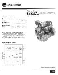
Fuels, Lubricants, and Coolant<strong>Diesel</strong> Engine OilUse preferably multi-viscosity oils based on theexpected air temperature range during the period betweenoil changes.50˚C122˚F<strong>John</strong> <strong>Deere</strong> PLUS-50 is the preferred diesel engineoil.Oil meeting one of the following specifications are alsorecommended:• ACEA Oil Sequence E7• ACEA Oil Sequence E6• ACEA Oil Sequence E5• ACEA Oil Sequence E4SAE 15W-40SAE 10W-40SAE 5W-30SAE 0W-4040˚C30˚C20˚C10˚C0˚C-10˚C104˚F86˚F68˚F50˚F32˚F14˚FExtended service intervals may apply when <strong>John</strong> <strong>Deere</strong>PLUS-50, ACEA E7, ACEA E6, ACEA E5, or ACEA E4engine oils are used. Consult your <strong>John</strong> <strong>Deere</strong> dealer formore information.Other oils may be used if they meet one or more of thefollowing:• <strong>John</strong> <strong>Deere</strong> TORQ-GARD SUPREME• API Service Category CI-4 PLUS• API Service Category CI-4• API Service Category CH-4• ACEA Oil Sequence E3-20˚C -4˚F-30˚C -22˚F-40˚C -40˚F<strong>Diesel</strong> Engine OilTS1668A –UN–14DEC01When using the specified <strong>John</strong> <strong>Deere</strong> oil filter with the oilshown in the following table for each engine, thecorresponding service interval applies. Intervals shown inthe table are the maximum (not-to-exceed) serviceintervals.PLUS-50 is a trademark of <strong>Deere</strong> & Company.TORQ-GARD SUPREME is a trademark of <strong>Deere</strong> & CompanyContinued on next pageOUOD006,0000002–19–31MAY06–1/210-7 060106PN=31
Fuels, Lubricants, and CoolantRecommended Engine Oil and Filter Service IntervalsEngine Type PLUS-50 and TORQ-GARDACEA-E7/E6/E5/E4 SUPREME or APIOils OnlyCI-4 Plus, CI-4/CH-4,ACEA-E3 OilsEmission 375 Hours 250 HoursNon-Certified andTier I EmissionCertifiedTier II Emission 500 Hours 250 HoursCertified (3029TF270)<strong>Diesel</strong> fuel quality and sulfur content must comply with allexisting emissions regulations for the area in which theengine operates.If diesel fuel with sulfur content greater than 0.05% (500ppm) is used, reduce the oil and filter service interval by100 hours.If diesel fuel with sulfur content greater than 0.5% (5000ppm) is used, reduce the service interval by 50%.<strong>Diesel</strong> fuel with sulfur content greater than 1.0% (10,000ppm) is not recommended.PLUS-50 is a trademark of <strong>Deere</strong> & Company.OUOD006,0000002–19–31MAY06–2/2Mixing of LubricantsIn general, avoid mixing different brands or types of oil.Oil manufacturers blend additives in their oils to meetcertain specifications and performance requirements.Consult your <strong>John</strong> <strong>Deere</strong> dealer to obtain specificinformation and recommendations.Mixing different oils can interfere with the properfunctioning of these additives and degrade lubricantperformance.DX,LUBMIX–19–18MAR96–1/110-8 060106PN=32
Fuels, Lubricants, and CoolantOILSCANand COOLSCANOILSCANand COOLSCAN are <strong>John</strong> <strong>Deere</strong> samplingprograms to help you monitor machine performance andidentify potential problems before they cause seriousdamage.Oil and coolant samples should be taken from eachsystem prior to its recommended change interval.Check with your <strong>John</strong> <strong>Deere</strong> dealer for the availability ofOILSCAN and COOLSCAN kits.T6828AB –UN–15JUN89T6829AB –UN–18OCT88OILSCAN is a registered trademark of <strong>Deere</strong> & Company.COOLSCAN is a trademark of <strong>Deere</strong> & Company.DX,OILSCAN–19–02DEC02–1/1Alternative and Synthetic LubricantsConditions in certain geographical areas may requirelubricant recommendations different from those printed inthis manual.Some <strong>John</strong> <strong>Deere</strong> brand coolants and lubricants may notbe available in your location.Consult your <strong>John</strong> <strong>Deere</strong> dealer to obtain information andrecommendations.Synthetic lubricants may be used if they meet theperformance requirements as shown in this manual.The temperature limits and service intervals shown in thismanual apply to both conventional and synthetic oils.Re-refined base stock products may be used if thefinished lubricant meets the performance requirements.DX,ALTER–19–15JUN00–1/110-9 060106PN=33
Fuels, Lubricants, and CoolantLubricant StorageYour equipment can operate at top efficiency onlywhen clean lubricants are used.Use clean containers to handle all lubricants.Whenever possible, store lubricants and containers inan area protected from dust, moisture, and othercontamination. Store containers on their side to avoidwater and dirt accumulation.Make certain that all containers are properly marked toidentify their contents.Properly dispose of all old containers and any residuallubricant they may contain.DX,LUBST–19–18MAR96–1/1GreaseUse grease based on NLGI consistency numbers and theexpected air temperature range during the service interval.<strong>John</strong> <strong>Deere</strong> SD POLYUREA GREASE is preferred.The following greases are also recommended• <strong>John</strong> <strong>Deere</strong> HD LITHIUM COMPLEX GREASE• <strong>John</strong> <strong>Deere</strong> HD WATER RESISTANT GREASE• <strong>John</strong> <strong>Deere</strong> GREASE-GARDOther greases may be used if they meet the following:NLGI Performance Classification GC-LBIMPORTANT: Some types of grease thickeners arenot compatible with others. Consultyour grease supplier before mixingdifferent types of greaseTS1673 –UN–31OCT03GREASE-GARD is a trademark of <strong>Deere</strong> & CompanyDX,GREA1–19–07NOV03–1/110-10 060106PN=34
Fuels, Lubricants, and Coolant<strong>Diesel</strong> Engine CoolantThe engine cooling system is filled to provideyear-round protection against corrosion and cylinderliner pitting, and winter freeze protection to -37°C(-34°F). If protection at lower temperatures is required,consult your <strong>John</strong> <strong>Deere</strong> dealer for recommendations.<strong>John</strong> <strong>Deere</strong> COOL-GARD Prediluted Coolant ispreferred for service.<strong>John</strong> <strong>Deere</strong> COOL-GARD Prediluted Coolant isavailable in a concentration of either 50% ethyleneglycol or 55% propylene glycol.Additional recommended coolantsThe following engine coolant is also recommended:• <strong>John</strong> <strong>Deere</strong> COOL-GARD Coolant Concentrate in a40% to 60% mixture of concentrate with qualitywater.<strong>John</strong> <strong>Deere</strong> COOL-GARD coolants do not require useof supplemental coolant additives, except for periodicreplenishment of additives during the drain interval.Other fully formulated coolantsOther fully formulated low silicate ethylene orpropylene glycol base coolants for heavy-duty enginesmay be used if they meet one of the followingspecifications:• ASTM D6210 prediluted (50%) coolant• ASTM D6210 coolant concentrate in a 40% to 60%mixture of concentrate with quality waterCoolants meeting ASTM D6210 do not require use ofsupplemental coolant additives, except for periodicreplenishment of additives during the drain interval.Other low silicate ethylene glycol base coolants forheavy-duty engines may also be used if they meet oneof the following specifications:• ASTM D4985 ethylene glycol base prediluted (50%)coolant• ASTM D4985 ethylene glycol base coolantconcentrate in a 40% to 60% mixture of concentratewith quality waterCoolants meeting ASTM D4985 require an initialcharge of supplemental coolant additives, formulatedfor protection of heavy duty diesel engines againstcorrosion and cylinder liner erosion and pitting. Theyalso require periodic replenishment of additives duringthe drain interval.Other coolantsIt is possible that neither <strong>John</strong> <strong>Deere</strong> COOL-GARD norcoolants meeting one of the coolant standards listedabove is available in the geographical area whereservice is performed. If these coolants are unavailable,use a coolant concentrate or prediluted coolant with aquality additive package that provides cylinder linercavitation protection and protects the cooling systemmetals (cast iron, aluminum alloys, and copper alloyssuch as brass) from corrosion.The additive package must be part of one of thefollowing coolant mixtures:• ethylene glycol or propylene glycol base prediluted(40% to 60%) coolant• ethylene glycol or propylene glycol base coolantconcentrate in a 40% to 60% mixture of concentratewith quality waterWater qualityCoolants requiring supplemental coolant additivesCOOL-GARD is a trademark of <strong>Deere</strong> & CompanyContinued on next page10-11 060106PN=35DX,COOL3–19–27OCT05–1/2
Fuels, Lubricants, and CoolantWater quality is important to the performance of thecooling system. Distilled, deionized, or demineralizedwater is recommended for mixing with ethylene glycoland propylene glycol base engine coolant concentrate.IMPORTANT: Do not mix ethylene glycol andpropylene glycol base coolants.IMPORTANT: Do not use cooling system sealingadditives or antifreeze that containssealing additives.DX,COOL3–19–27OCT05–2/210-12 060106PN=36
Fuels, Lubricants, and CoolantAdditional Information About <strong>Diesel</strong> Engine Coolants and Supplemental CoolantAdditivesEngine coolants are a combination of three chemicalcomponents: ethylene glycol or propylene glycolantifreeze, inhibiting coolant additives, and qualitywater.Coolant specificationsSome products, including <strong>John</strong> <strong>Deere</strong> COOL-GARDPrediluted Coolant, are fully formulated coolants thatcontain all three components in their correctconcentrations. Do not add an initial charge ofsupplemental coolant additives to these fullyformulated products.Coolants meeting ASTM D6210 do not require aninitial charge of supplemental coolant additives.Some coolant concentrates, including <strong>John</strong> <strong>Deere</strong>COOL-GARD Coolant Concentrate, contain both glycolantifreeze and inhibiting coolant additives. Mix theseproducts with quality water, but do not add an initialcharge of supplemental coolant additives.Coolants meeting ASTM D4985 require an initialcharge of supplemental coolant additives.Replenish coolant additivesThe concentration of coolant additives is graduallydepleted during engine operation. Periodicreplenishment of inhibitors is required, even when<strong>John</strong> <strong>Deere</strong> COOL-GARD or another fully formulatedcoolant is used. Follow the recommendations in thismanual for the use of supplemental coolant additives.Why use supplemental coolant additives?Operating without proper coolant additives will result inincreased corrosion, cylinder liner erosion and pitting,and other damage to the engine and cooling system. Asimple mixture of ethylene glycol or propylene glycoland water will not give adequate protection.Use of supplemental coolant additives reducescorrosion, erosion, and pitting. These chemicalsreduce the number of vapor bubbles in the coolant andhelp form a protective film on cylinder liner surfaces.This film acts as a barrier against the harmful effectsof collapsing vapor bubbles.Avoid automotive-type coolantsNever use automotive-type coolants (such as thosemeeting ASTM D3306). These coolants do not containthe correct additives to protect heavy-duty dieselengines. They often contain a high concentration ofsilicates and may damage the engine or coolingsystem.Water qualityWater quality is important to the performance of thecooling system. Distilled, deionized, or demineralizedwater is recommended for mixing with ethylene glycoland propylene glycol base engine coolant concentrate.All water used in the cooling system should meet thefollowing minimum specifications for quality:Chlorides
Fuels, Lubricants, and CoolantEthylene GlycolFreeze Protection Limit40% -24°C (-12°F)50% -37°C (-34°F)60% -52°C (-62°F)Propylene GlycolFreeze Protection Limit40% -21°C (-6°F)50% -33°C (-27°F)60% -49°C (-56°F)DO NOT use a coolant-water mixture greater than60% ethylene glycol or 60% propylene glycol.DX,COOL7–19–19DEC03–2/2Testing <strong>Diesel</strong> Engine CoolantTesting <strong>Diesel</strong> Engine CoolantMaintaining adequate concentrations of glycol andinhibiting additives in the coolant is critical to protectthe engine and cooling system against freezing,corrosion, and cylinder liner erosion and pitting.Test the coolant solution at intervals of 12 months orless and whenever excessive coolant is lost throughleaks or overheating.Coolant test stripsCoolant test strips are available from your <strong>John</strong> <strong>Deere</strong>dealer. These test strips provide a simple, effectivemethod to check the freeze point and additive levels ofyour engine coolant.Compare the results to the supplemental coolantadditive (SCA) chart to determine the amount ofinhibiting additives in your coolant and whether more<strong>John</strong> <strong>Deere</strong> COOLANT CONDITIONER should beadded.COOLSCAN and COOLSCAN PLUSFor a more thorough evaluation of your coolant,perform a COOLSCAN or COOLSCAN PLUS analysis,where available. See your <strong>John</strong> <strong>Deere</strong> dealer forinformation.COOLSCAN is a trademark of <strong>Deere</strong> & CompanyCOOLSCAN PLUS is a trademark of <strong>Deere</strong> & CompanyDX,COOL9–19–19DEC03–1/110-14 060106PN=38
Fuels, Lubricants, and CoolantSupplemental Coolant AdditivesThe concentration of coolant additives is graduallydepleted during engine operation. For allrecommended coolants, replenish additives betweendrain intervals by adding a supplemental coolantadditive every 12 months or as determined necessaryby coolant testing.<strong>John</strong> <strong>Deere</strong> COOLANT CONDITIONER isrecommended as a supplemental coolant additive in<strong>John</strong> <strong>Deere</strong> engines.IMPORTANT: Do not add a supplemental coolantadditive when the cooling system isdrained and refilled with <strong>John</strong><strong>Deere</strong>COOL-GARD.If other coolants are used, consult the coolant supplierand follow the manufacturer’s recommendation for useof supplemental coolant additives.The use of non-recommended supplemental coolantadditives may result in additive drop-out and gelationof the coolant.Add the manufacturer’s recommended concentration ofsupplemental coolant additive. DO NOT add more thanthe recommended amount.COOL-GARD is a trademark of <strong>Deere</strong> & CompanyDX,COOL4–19–07NOV03–1/1Operating in Warm Temperature Climates<strong>John</strong> <strong>Deere</strong> engines are designed to operate using glycolbase engine coolants.Always use a recommended glycol base engine coolant,even when operating in geographical areas where freezeprotection is not required.IMPORTANT: Water may be used as coolant inemergency situations only.Foaming, hot surface aluminum andiron corrosion, scaling, and cavitationwill occur when water is used as thecoolant, even when coolantconditioners are added.Drain cooling system and refill withrecommended glycol base enginecoolant as soon as possible.DX,COOL6–19–18MAR96–1/110-15 060106PN=39
Fuels, Lubricants, and CoolantDisposing of CoolantImproperly disposing of engine coolant can threaten theenvironment and ecology.Use leakproof containers when draining fluids. Do not usefood or beverage containers that may mislead someoneinto drinking from them.Do not pour waste onto the ground, down a drain, or intoany water source.Inquire on the proper way to recycle or dispose of wastefrom your local environmental or recycling center, or fromyour <strong>John</strong> <strong>Deere</strong> engine distributor or servicing dealer.Recycle WasteTS1133 –UN–26NOV90RG,RG34710,7543–19–24JAN03–1/110-16 060106PN=40
Engine Operating GuidelinesInstrument (Gauge) PanelsIMPORTANT: Any time an electric gauge or meterdoes not register correctly, replace itwith a new one. Do not attempt to repairit.All controls and gauges covered in this manual areoptional equipment for <strong>John</strong> <strong>Deere</strong> <strong>OEM</strong> <strong>Engines</strong>. Theymay be provided by the equipment manufacturer insteadof <strong>John</strong> <strong>Deere</strong>. The following information applies only tothose controls and gauges provided by <strong>John</strong> <strong>Deere</strong>.Continued on next pageOUOD006,0000001–19–26MAY06–1/815-1 060106PN=41
Engine Operating GuidelinesEarlier Instrument (Gauge) Panel (North America)Following is a brief description of the components on the<strong>John</strong> <strong>Deere</strong> instrument (gauge) panel:A—Oil Pressure Gauge - Indicates engine oil pressure.B—Coolant Temperature Gauge - Indicates the enginecoolant temperature.C—Key Switch - The four position key switch controls theelectrical system.D—Tachometer (optional) - Indicates engine speed inrevolutions per minute (rpm).E—Reset (Safety) Switch - Overrides safety shutdownswitch when depressed and held in during engine start-up.Hold button in until engine oil pressure is at a safeoperating level.F—Fuse Holder - Contains 14 amp fuse.G—Ammeter - Indicates charging current within electricalsystem.North American Instrument Panel (Earlier <strong>Engines</strong>)RG11527 –UN–01DEC00H—Hour Meter (optional) - Indicates the operating hoursof the engine while key switch is in the “ON” position. Thehour meter should be used as a guide for schedulingperiodic service.I—Hand Throttle (optional) - Controls engine speed.A—Oil Pressure GaugeB—Coolant Temperature GaugeC—Key SwitchD—TachometerE—Reset (Safety) SwitchF—Fuse HolderG—AmmeterH—Hour MeterI—Hand ThrottleContinued on next pageOUOD006,0000001–19–26MAY06–2/815-2 060106PN=42
Engine Operating GuidelinesLater Instrument (Gauge) Panel (North America)IMPORTANT: Any time an electric gauge or meterdoes not register correctly, replace itwith a new one. Do not attempt to repairit.Following is a brief description of the components oninstrument (gauge) panel:A—Tachometer with Hourmeter (Optional) - Thetachometer with hourmeter indicates engine speed inrevolutions per minute (rpm) and shows the operatinghours of the engine while key switch is in the “ON”position. The hour meter should be used as a guide forscheduling periodic service.B—Oil Pressure Gauge - The oil pressure gaugeindicates engine oil pressure. If the engine oil pressurefalls below a safe operating pressure, the engine will shutdown.C—Voltmeter Gauge - The voltmeter indicates systembattery voltage.D—Coolant Temperature Gauge - The coolanttemperature gauge indicates the engine coolanttemperature. If coolant temperature rises above thepreset, safe operating temperature, the engine will shutdown.E—Pre-Heat Button - Press button to activate thepreheater for cold weather starting.F—Reset (Safety) Switch- Reset button will pop out andshut down the engine if the coolant temperature is toohigh or oil pressure is too low. Press in and hold whilestarting engine until oil pressure is at a safe operatinglevel.Instrument Panel and Gauges (Later <strong>Engines</strong>)A—Tachometer with Hourmeter (Optional)B—Oil Pressure GaugeC—Voltmeter GaugeD—Coolant Temperature GaugeE—Preheat ButtonF—Reset (Safety) SwitchG—Fuse HolderH—Key SwitchI—Throttle (Optional)J—Hourmeter (Optional)RG13360 –UN–06FEB04G—Fuse Holder - Contains 14 amp fuse.H—Key Switch - The key switch controls the electricalsystem. Positions of key switch are marked as follows:OFF, ON, and START.Continued on next pageOUOD006,0000001–19–26MAY06–3/815-3 060106PN=43
Engine Operating GuidelinesI—Throttle (Optional) - The throttle control is used tocontrol engine speed.J—Hourmeter (Optional) - The hourmeter indicates theoperating hours of the engine while key switch is in the“ON” position. The hour meter should be used as a guidefor scheduling periodic service.Continued on next pageOUOD006,0000001–19–26MAY06–4/815-4 060106PN=44
Engine Operating GuidelinesAEZ Instrument (Gauge) Panel (Except North America)A—Oil Pressure Gauge - The oil pressure gaugeindicates engine oil pressure.B—Coolant Temperature Gauge - The coolanttemperature gauge indicates the engine coolanttemperature.C—Engine Control Light - The engine control lightindicates that the engine protection is activated.D—Oil Pressure Light - The oil pressure light illuminateswhen the key switch is turned to the CONTROL position.The light will remain on until the engine is started and thespecified oil pressure is reached. If oil pressure is lostduring engine operation, the light will illuminate andprotection circuitry will stop the engine. The oil pressurelight will remain on, indicating that the engine was stoppeddue to a low oil pressure condition.E—Alternator Light - The alternator light illuminateswhen the key is turned to the CONTROL position. Thelight will remain on until the engine is started. After theengine is running, if the alternator stops charging, the lightwill illuminate and protection circuitry will stop the engine.The alternator light will remain on indicating the enginewas stopped due to the alternator not charging.AEZ Instrument PanelA—Oil Pressure GaugeB—Coolant Temperature GaugeC—Engine Control LightD—Oil Pressure LightE—Alternator LightF—Coolant Temperature LightG—Fuel Level LightH—Key SwitchI—Hour MeterJ—TachometerRG11590 –UN–08DEC00F—Coolant Temperature Light - The coolanttemperature light illuminates only if the engine hasoverheated. After the engine is running, if the engineoverheats, the light will illuminate and protection circuitrywill stop the engine. The coolant temperature light willremain on indicating the engine was stopped due to theengine overheating.G—Fuel Level Light - The fuel level light illuminates onlyif the engine has stopped due to fuel tank being empty.After the engine is running, if the engine runs out of fuel,the light will illuminate. The fuel level light will remain onindicating the engine was stopped due to the fuel tankbeing empty.H—Key Switch - The key switch controls the electricalsystem.Continued on next pageOUOD006,0000001–19–26MAY06–5/815-5 060106PN=45
Engine Operating GuidelinesI—Hour Meter - Indicates the operating hours of theengine while key switch is in the “ON” position. The hourmeter should be used as a guide for scheduling periodicservice.J—Tachometer - Indicates engine speed in revolutionsper minute (rpm).Continued on next pageOUOD006,0000001–19–26MAY06–6/815-6 060106PN=46
Engine Operating GuidelinesVDO Instrument (Gauge) Panel (Except NorthAmerica)A—Oil Pressure Gauge - The oil pressure gaugeindicates engine oil pressure.B—Coolant Temperature Gauge - The coolanttemperature gauge indicates coolant temperature.C—Tachometer - The tachometer indicates engine speedin hundreds of revolutions per minute (rpm).The engine control system consists of the following:D—Engine Control Light - The engine control lightilluminates after the engine has started and oil pressure isup to specification. The light indicates that the engineprotection circuitry is activated.E—Preheater Light - The preheater light illuminateswhen the key is turned to the bulb test position (positionI). It should go off after approximately five seconds. Whenthe key switch is held in position II, the engine preheateris energized and the preheater light illuminates.A—Oil Pressure GaugeB—Coolant Temperature GaugeC—TachometerD—Engine Control LightE—Preheater LightF—Fuel Level LightG—Battery LightH—Oil Pressure LightI—Coolant Temperature LightJ—Key/Start SwitchK—Hour MeterRG10606B –UN–20OCT99F—Fuel Level Light - The fuel level light illuminateswhen the key is turned to the bulb test position (positionI). It should go off after approximately five seconds. Afterthe engine is running, if the engine runs out of fuel, thelight will illuminate. The fuel level light will remain onindicating the engine was stopped due to the fuel tankbeing empty.G—Battery Light - The battery light illuminates when thekey is turned to the bulb test position (position I). It shouldgo off after approximately five seconds. After the engine isrunning, if the alternator stops charging, the light willilluminate and protection circuitry will stop the engine. Thebattery light will remain on indicating the engine wasstopped due to the alternator not charging.Continued on next pageOUOD006,0000001–19–26MAY06–7/815-7 060106PN=47
Engine Operating GuidelinesH—Oil Pressure Light - The oil pressure light illuminateswhen the key switch is turned to the bulb test position(position I). The light will remain on until the engine isstarted and the specified oil pressure is reached. If oilpressure is lost during engine operation, the light willilluminate and protection circuitry will stop the engine. Theoil pressure light will remain on, indicating that the enginewas stopped due to a low oil pressure condition.I—Coolant Temperature Light - The coolant temperaturelight illuminates when the key is turned to the bulb testposition (position I). It should go off after approximatelyfive seconds. After the engine is running, if the engineoverheats, the light will illuminate and protection circuitrywill stop the engine. The coolant temperature light willremain on indicating the engine was stopped due to theengine overheating.Other components on the instrument panel:J—Key/Start Switch - The four-position key start switchcontrols the electrical system.K—Hour Meter - The hour meter is an integral part of thetachometer. It shows the accumulated hours of engineservice. The hour meter operates when the engine isrunning and accumulated hours are displayed in hoursand tenths of hours.OUOD006,0000001–19–26MAY06–8/815-8 060106PN=48
Engine Operating GuidelinesAuxiliary Gear Drive LimitationsIMPORTANT: When attaching an air compressor,hydraulic pump, or other accessory tobe driven by the auxiliary gear drive(engine timing gear train at front ofengine), power requirements of theaccessory must be limited to valueslisted below:Power Levels For Right-Hand Auxiliary Gear Drive:• 16 kW (22 hp) Continuous Operation 1• 28 kW (37.5 hp) Intermittent Operation 1Auxiliary Gear DriveCD30354 –UN–03FEB931At 2400 engine rpm.RG,RG34710,5047–19–30JAN98–1/1Generator Set (Standby) ApplicationsTo assure that your engine will deliver efficient standbyoperation when needed, start engine and run at ratedspeed (with 50%—70% load) for 30 minutes every 2weeks. DO NOT allow engine to run extended period oftime with no load.RG,RG34710,5048–19–30JAN98–1/1Starting The EngineThe following instructions apply to the optional controlsand instruments available through the <strong>John</strong> <strong>Deere</strong> PartsDistribution Network. The controls and instruments foryour engine may be different from those shown here;always follow manufacturer’s instructions.Continued on next pageRG,RG34710,5049–19–30JAN98–1/415-9 060106PN=49
Engine Operating GuidelinesCAUTION: Before starting engine in a confinedbuilding, install proper outlet exhaustventilation equipment. Always use safetyapproved fuel storage and piping.NOTE: If temperature is below 0 °C (32 °F), it may benecessary to use cold weather starting aids (SeeCOLD WEATHER OPERATION, later in thissection).1. Perform all prestarting checks outlined in Lubrication &Maintenance/Daily Section later in this manual.Avoid Toxic FumesTS220 –UN–23AUG882. Open the fuel supply shut-off valve, if equipped.RG,RG34710,5049–19–30JAN98–2/43. If equipped with PTO clutch, pull lever (arrow) rearward(away from engine) to disengage PTO clutch.PTO Clutch LeverRG5602 –UN–16JUN00Continued on next pageRG,RG34710,5049–19–30JAN98–3/415-10 060106PN=50
Engine Operating Guidelines4. Pull hand throttle (A) 1/3 of the way out. Turn thehandle in either direction to lock it in place.5. If equipped, depress and hold reset button (B) whilestarting.IMPORTANT: Do not operate the starter for more than30 seconds at a time. To do so mayoverheat the starter. If the engine doesnot start the first time, wait at least 2minutes before trying again. If enginedoes not start after four attempts, seeTroubleshooting Section.6. Turn the key switch (C) clockwise to crank the engine.When the engine starts, release the key so that itreturns to the “ON” position.IMPORTANT: If the key switch is released before theengine starts, wait until the starter andthe engine stop turning before tryingagain. This will prevent possibledamage to the starter and/or flywheel.7. After the engine starts, continue to hold the resetbutton in until the oil pressure gauge (D) reads at least105 kPa (1.05 bar) (15 psi). The safety controls will notallow the engine to run at a lower oil pressure unlessthe reset button is held in.North American Instrument PanelRG11532 –UN–01DEC00IMPORTANT: Should the engine die while operatingunder load, immediately disengage PTOclutch and restart the engine.Overheating of turbocharger parts mayoccur when oil flow is stopped.8. Check all gauges for normal engine operation. Ifoperation is not normal, stop the engine and determinethe cause.A—Hand ThrottleB—Reset ButtonC—Key SwitchD—Oil Pressure GaugeAEZ Instrument Panel (Except North America)RG11592 –UN–17JAN01VDO Instrument Panel (Except North America)RG11588 –UN–08DEC00RG,RG34710,5049–19–30JAN98–4/415-11 060106PN=51
Engine Operating GuidelinesBreak-In ServiceCheck Engine Oil LevelRG7314 –UN–29NOV00Dipstick MarkingsRG11528 –UN–01DEC00A—Full MarkThe engine is ready for normal operation. However,extra care during the first 100 hours of operation willresult in more satisfactory long-term engineperformance and life. DO NOT exceed 100 hours ofoperation with break-in oil.1. This engine is factory-filled with a special break-inoil. Operate the engine at heavy loads with minimalidling during the break-in period.IMPORTANT: Do not add makeup oil until the levelis BELOW the ADD mark or lowerarrow on dipstick. If make-up oil isrequired during the break-in period,an additional 100 hour break-inperiod is required. <strong>John</strong> <strong>Deere</strong>Engine Break-In Oil (TY22041)should be used to make up any oilconsumed during the break-inperiod.DO NOT fill above the top of themark (A) or crosshatch pattern (B),whichever is present. Oil levelsanywhere within arrows orB—Crosshatchcrosshatch are considered in theacceptable operating range.2. Check engine oil level more frequently. If oil mustbe added, <strong>John</strong> <strong>Deere</strong> Engine Break-In Oil ispreferred. See ENGINE BREAK-IN OIL, in Fuels,Lubricants, and Coolant Section.3. Check oil pressure and coolant temperature whileengine is operating. See specification.SpecificationEngine 1 —Oil Pressure at FullLoad Rated Speed...................................345 ± 103 kPa (3.45 ± 1.03bar) (50 ± 15 psi)Minimum Oil Pressure at RatedSpeed...............................................................275 (2.75 bar) (40 psi)Minimum Oil Pressure at 850rpm...........................................................105 kPa (1.05 bar) (15 psi)Coolant Temperature Range ...................... 82°—94°C (180°—202°F)4. During the first 20 hours, avoid prolonged periodsof engine idling or sustained maximum loadoperation. Vary the engine speed throughout thisperiod. If engine will idle longer than 5 minutes,stop engine.1At normal operating temperature of 115 °C (240 °F) sump.Continued on next pageRG,RG34710,5046–19–11FEB03–1/215-12 060106PN=52
Engine Operating GuidelinesAEZ Instrument Panel (Except North America)RG11591 –UN–08DEC00North American Instrument Panel5. Watch coolant temperature gauge (A) closely. If coolanttemperature rises above 112°C (234°F), reduce load onengine. Unless temperature drops quickly, stop the engineand determine the cause before resuming operation.RG11531 –UN–01DEC00VDO Instrument Panel (Except North America)A—Coolant Temperature GaugeRG11587 –UN–07DEC00NOTE: When the coolant temperature gauge readsapproximately 115°C (239°F), the engine willshutdown automatically, if equipped with safetycontrols.6. The tension on newly installed belts should be checkeddaily for the first few days of operation because of theinitial stretching. Also, check belts for proper seating inpulley grooves.RG,RG34710,5046–19–11FEB03–2/215-13 060106PN=53
Engine Operating GuidelinesAfter Break-In ServiceEngine Mounted Oil FilterRG11529 –UN–01DEC00Engine Mounted Oil FilterRG11530 –UN–01DEC00NOTE: If the engine has significant operating time at idle,constant speeds, and/or light load usage, ormake-up oil is required in the first 100 hourperiod, a longer break-in period may be required.In these situations, an additional 100 hourbreak-in period is recommended using a newchange of <strong>John</strong> <strong>Deere</strong> Engine Break-In Oil andnew <strong>John</strong> <strong>Deere</strong> oil filter.After break-in service, change engine oil and oil filter (A)according to maintenance interval indicated below.All except 3029TF270 <strong>Engines</strong>: See CHANGINGENGINE OIL AND REPLACING OIL FILTER inLubrication and Maintenance/250 Hour Section.3029 <strong>Engines</strong> with Remote Oil FilterA—Oil FilterRG11549 –UN–06DEC003029TF270 <strong>Engines</strong>: (See CHANGING ENGINE OILAND REPLACING OIL FILTER in Lubrication andMaintenance/500 Hour Section.Fill crankcase with seasonal viscosity grade oil. (SeeDIESEL ENGINE OIL in Fuels, Lubricants, and CoolantSection.)OURGP12,00001E3–19–04MAR03–1/115-14 060106PN=54
Engine Operating GuidelinesNormal Engine OperationObserve engine coolant temperature and engine oilpressure. Temperatures and pressures will varybetween engines and with changing operatingconditions, temperatures, and loads.Normal engine coolant operating temperature range is82°–94°C (180°–202°F). If coolant temperature risesabove 112°C (234°F), reduce load on engine. Unlesstemperature drops quickly, stop engine and determinecause before resuming operation.Operate the engine under a lighter load and at slowerthan normal speed for first 15 minutes after start-up.DO NOT run engine at slow idle.IMPORTANT: Should the engine die whileoperating under load, immediatelyremove load and restart the engine.Overheating of the turbochargerparts may occur when oil flow isstopped.Stop engine immediately if there are any signs of partfailure. Symptoms that may be early signs of engineproblems are:• Sudden drop in oil pressure• Abnormal coolant temperatures• Unusual noise or vibration• Sudden loss of power• Excessive black exhaust• Excessive fuel consumption• Excessive oil consumption• Fluid leaksRG,RG34710,5045–19–30JAN98–1/115-15 060106PN=55
Engine Operating GuidelinesCold Weather OperationCAUTION: Ether injector starting fluid is highlyflammable. DO NOT use starting fluid onengines equipped with air intake heaters.DO NOT use starting fluid near fire, sparks, orflames. DO NOT incinerate or puncture astarting fluid container.<strong>Engines</strong> may be equipped with intake air heaters, coolantheaters, or ether injectors as a cold weather starting aid.Handle Starting Fluid with CareTS1356 –UN–18MAR92Starting aids are required below 0°C (32°F). They willenhance starting performance above these temperaturesand may be needed to start applications that have highparasitic loads during cranking and/or start acceleration toidle.Using correct grade of oil (per engine and machineoperator’s manual) is critical to achieving adequate coldweather cranking speed.Other cold weather starting aids are required attemperatures below -30°C (-22°F) or at altitudes above1500 m (5000 ft).1. Follow steps 1—4 as listed under “STARTING THEENGINE”, then proceed as follows according to theinstrument (control) panel on your engine.2. Switch on the air intake heater for 30 seconds oractivate ether injector by following suppliersinstructions.Cold Weather Starting GuidelinesRG11521 –19–10JAN013. Follow remaining steps 5—8 as listed under“STARTING THE ENGINE” earlier in this section.Additional information on cold weather operation isavailable from your authorized servicing dealer.RG,RG34710,5050–19–11FEB03–1/115-16 060106PN=56
Engine Operating GuidelinesWarming EngineIMPORTANT: To assure proper lubrication, operateengine at or below 1200 rpm with noload for 1–2 minutes. Extend this period2–4 minutes when operating attemperatures below freezing.<strong>Engines</strong> used in generator setapplications where the governor islocked at a specified speed may nothave a slow idle function. Operate theseengines at high idle for 1 to 2 minutesbefore applying the load. Thisprocedure does not apply to standbygenerator sets where the engine isloaded immediately upon reaching ratedspeed.1. Check oil pressure gauge (A) as soon as engine starts.If gauge needle does not rise above minimum oilpressure specification of 105 kPa (1.05 bar) (15.0 psi)within 5 seconds, stop the engine and determine thecause. Normal engine oil pressure is 345 ±103 kPa(3.45 bar ± 1.03 bar) (50 ±15 psi) at rated full loadspeed (1800–2500 rpm) with oil at normal operatingtemperature of 105°C (221°F).North American Instrument PanelRG11533 –UN–01DEC002. Watch coolant temperature gauge (B). Do not placeengine under full load until it is properly warmed up.The normal engine coolant temperature range is 82°–94°C (180°–202°F).NOTE: It is a good practice to operate the engine under alighter load and at lower speeds than normal forthe first few minutes after start-up.A—Oil Pressure GaugeB—Coolant Temperature GaugeAEZ Instrument Panel (Except North America)RG11593 –UN–08DEC00VDO Instrument Panel (Except North America)RG10613 –UN–21OCT99RG,RG34710,5051–19–30JAN98–1/115-17 060106PN=57
Engine Operating GuidelinesChanging Engine Speed-Standard(Mechanical) GovernorNOTE: Throttle levers are usually supplied by <strong>OEM</strong>manufacturer. Consult supplier literature tofamiliarize yourself with throttle lever used on yourengine.To increase engine speed, turn throttle handle (A) to thehorizontal position and pull out until desired engine speedis obtained. Turn the handle in either direction to lockthrottle position. The handle is pushed inward to decreaseengine speed.A—Throttle HandleThrottle Handle on North American Instrument PanelRG11534 –UN–01DEC00RG,RG34710,5052–19–30JAN98–1/1Idling EngineAvoid excessive engine idling. Prolonged idling maycause the engine coolant temperature to fall below itsnormal range. This, in turn, causes crankcase oildilution, due to incomplete fuel combustion, andpermits formation of gummy deposits on valves,pistons, and piston rings. It also promotes rapidaccumulation of engine sludge and unburned fuel inthe exhaust system.Once an engine is warmed to normal operatingtemperatures, engine should be idled at slow idlespeed. Slow idle speed for this engine is 850 rpm atfactory. If an engine will be idling for more than 5minutes, stop and restart later, or set engine speed at1200 rpm.NOTE: Generator set applications where the governoris locked at a specified speed may not have aslow idle function. These engines will idle at noload governed speed (high idle).RG,RG34710,5053–19–11FEB03–1/115-18 060106PN=58
Engine Operating GuidelinesStopping The Engine1. Pull PTO clutch lever (arrow) rearward (away fromengine) to disengage clutch, if equipped.PTO Clutch LeverRG5602 –UN–16JUN00Continued on next pageRG,RG34710,5054–19–30JAN98–1/215-19 060106PN=59
Engine Operating Guidelines2. Move the throttle handle (A) to slow idle on standard(mechanical) governor engines.IMPORTANT: Before stopping an engine that hasbeen operating at working load, idleengine at least 2 minutes at 1000–1200rpm to cool hot engine parts.<strong>Engines</strong> in generator set applications,where the governor is locked at aspecified speed and no slow idlefunction is available, run engine for atleast 2 minutes at fast idle and no load.3. Turn key switch to “OFF” position. Remove ignitionkey.IMPORTANT: Make sure that exhaust stack cap (raincap) is installed when engine is notrunning. This will prevent water and dirtfrom entering engine.A—Throttle HandleThrottle Handle on North American Instrument PanelRG11534 –UN–01DEC00Rain CapRG10616 –UN–16JUN00RG,RG34710,5054–19–30JAN98–2/215-20 060106PN=60
Engine Operating GuidelinesUsing A Booster Battery Or ChargerCAUTION: Gas given off by battery is explosive.Keep sparks and flames away from battery.Before connecting or disconnecting a batterycharger, turn charger off. Make last connectionand first disconnection at a point away frombattery. Always connect NEGATIVE (–) cablelast and disconnect this cable first.IMPORTANT: Be sure polarity is correct beforemaking connections. Reversed polaritywill damage electrical system. Alwaysconnect positive to positive andnegative to ground. Always use 12-voltbooster battery for 12-volt electricalsystems and 24-volt booster battery(ies)for 24-volt electrical systems.WARNING: Battery posts, terminals, and relatedaccessories contain lead and lead compounds, chemicalsknown to the State of California to cause cancer andreproductive harm. Wash hands after handling.A 12-volt booster battery can be connected in parallel withbattery(ies) on the unit to aid in cold weather starting.ALWAYS use heavy duty jumper cables.Exploding Battery12-Volt SystemTS204 –UN–23AUG88RG4678 –UN–14DEC881. Connect booster battery or batteries to produce therequired system voltage for your engine application.NOTE: To avoid sparks, DO NOT allow the free ends ofjumper cables to touch the engine.2. Connect one end of jumper cable to the POSITIVE (+)post of the booster battery.3. Connect the other end of the jumper cable to thePOSITIVE (+) post of battery connected to starter.4. Connect one end of the other jumper cable to theNEGATIVE (–) post of the booster battery.5. ALWAYS complete the hook-up by making the lastconnection of the NEGATIVE (–) cable to a goodground on the engine frame and away from thebattery(ies).24-Volt SystemA—12-Volt Machine Battery (ies)B—12-Volt Booster Battery (ies)C—Booster CableD—Cable to Starting MotorRG4698 –UN–14DEC88Continued on next pageRG,RG34710,4060–19–01JAN96–1/215-21 060106PN=61
Engine Operating Guidelines6. Start the engine. Disconnect jumper cablesimmediately after engine starts. Always disconnectNEGATIVE (–) cable first.RG,RG34710,4060–19–01JAN96–2/215-22 060106PN=62
Lubrication and MaintenanceObserve Service IntervalsAEZ Instrument Panel Hour MeterRG11594 –UN–08DEC00North American Instrument Panel Hour MeterUsing hour meter (A) as a guide, perform all services atthe hourly intervals indicated on following pages. At eachscheduled maintenance interval, perform all previousmaintenance operations in addition to the ones specified.Keep a record of hourly intervals and services performedusing charts provided in Lubrication and MaintenanceRecords Section.RG11589 –UN–08DEC00A—Hour MeterVDO Instrument Panel Hour MeterRG10618 –UN–21OCT99IMPORTANT: Recommended service intervals are fornormal operating conditions. ServiceMORE OFTEN if engine is operatedunder adverse conditions. Neglectingmaintenance can result in failures orpermanent damage to the engine.RG,RG34710,5056–19–30JAN98–1/120-1 060106PN=63
Lubrication and MaintenanceUse Correct Fuels, Lubricants, And CoolantIMPORTANT: Use only fuels, lubricants, and coolantsmeeting specifications outlined inFuels, Lubricants, and Coolant Sectionwhen servicing your <strong>John</strong> <strong>Deere</strong>Engine.Consult your <strong>John</strong> <strong>Deere</strong> Servicing Distributor or yournearest <strong>John</strong> <strong>Deere</strong> Parts Network for recommendedfuels, lubricants, and coolant. Also available arenecessary additives for use when operating engines intropical, arctic, or any other adverse conditions.<strong>John</strong> <strong>Deere</strong> PartsTS100 –UN–23AUG88RG,RG34710,5057–19–30JAN98–1/120-2 060106PN=64
Lubrication and MaintenanceLubrication And Maintenance Service IntervalChart—Prime Power <strong>Engines</strong>Lubrication and Maintenance Service IntervalsItem 250 Hour or 500 Hour or 2000 Hour orDaily6 Month 12 Month 24 MonthCheck Engine Oil and Coolant Level•Lubricate PTO Release BearingCheck Air Cleaner Dust Unloader Valve &Restriction Indicator aVisual Walk Around InspectionCheck Fuel FilterService Fire ExtinguisherLubricate PTO Clutch Shaft BearingService BatteryChange Engine Oil and Filter- All except3029TF270 <strong>Engines</strong> bCheck Fan and Alternator Belt TensionCheck PTO Clutch AdjustmentCheck Engine MountsChange Engine Oil and Filter- 3029TF270<strong>Engines</strong> cCheck Engine Ground ConnectionLubricate PTO Clutch Levers and Linkage (IfEquipped)Clean Crankcase Vent TubeCheck Air Intake Hoses, Connections, andSystemReplace Fuel Filter /Bleed SystemCheck Cooling SystemCoolant Solution Analysis-Add SCAs asneededPressure Test Cooling SystemCheck Engine SpeedsCheck and Adjust Valve ClearanceaReplace primary air cleaner element when restriction indicator shows a vacuum of 625 mm (25 in.) H2O.••••••••••••••••••••••As RequiredbChange the oil and filter for the first time after 100 hours maximum of operation, then every 250 hours thereafter. If recommended oils areused along with the specified <strong>John</strong> <strong>Deere</strong> oil filter, the oil change interval may be extended by 50 percent to 375 hours. (See DIESELENGINE OIL in Fuels, Lubricants, and Coolant section.)cChange the oil for the first time before 100 hours maximum of (break-in) operation, then every 500 hours thereafter. If PLUS-50 or ACEAE7/E6/E5/E4 oil is NOT used along with the specified <strong>John</strong> <strong>Deere</strong> oil filter, the oil change interval is reduced to 250 hours. (See DIESELENGINE OIL in Fuels, Lubricants, and Coolant section for oil pan and fuel sulfur content restrictions.)Continued on next pageRG,RG34710,5058–19–30MAY06–1/220-3 060106PN=65
Lubrication and MaintenanceLubrication and Maintenance Service IntervalsItem 250 Hour or 500 Hour or 2000 Hour orDaily6 Month 12 Month 24 MonthFlush and Refill Cooling System dTest ThermostatsAdd CoolantBleed Fuel SystemReplace Air Cleaner ElementsReplace BeltsInspect PTO Clutch (If Equipped)Check Fuses••As RequireddIf <strong>John</strong> <strong>Deere</strong> COOL-GARD is used, the flushing and refilling interval may be extended to 3000 hours or 36 months. If <strong>John</strong> <strong>Deere</strong>COOL-GARD is used and the coolant is tested annually AND additives are replenished by adding supplemental coolant additives (SCAs), theflushing and refilling interval may be extended to 5000 hours or 60 months, whichever occurs first.••••••RG,RG34710,5058–19–30MAY06–2/220-4 060106PN=66
Lubrication and MaintenanceLubricant And Maintenance Service IntervalChart—Generator (Standby) ApplicationsNOTE: The service intervals in the Lubrication andMaintenance Sections that follow reflect standardengines. Use service intervals listed below forgenerator (standby) applications. Match serviceitems below to titles in Lubrication andMaintenance Sections for procedures.Lubrication and Maintenance Service IntervalsItem Every 2 250 Hour or 500 Hour or 2000 Hour orWeeks 6 Month 12 Month 24 MonthOperate Engine at Rated Speed and•50%-70% Load a Minimum of 30 MinutesCheck Engine Oil and Coolant LevelCheck Fuel FilterLubricate PTO Release BearingsCheck Air Cleaner Dust Unloader Valve &Restriction Indicator Gauge aVisual Walkaround InspectionService Fire ExtinguisherLubricate PTO Clutch Shaft BearingsService BatteryChange Engine Oil and Replace Oil Filter-All Except 3029TF270 <strong>Engines</strong> bCheck Fan and Alternator Belt TensionCheck PTO Clutch AdjustmentCheck Engine MountsChange Engine Oil and Filter- 3029TF270<strong>Engines</strong> cCheck Engine Ground ConnectionClean Crankcase Vent TubeCheck Air Intake Hoses, Connections &SystemReplace Fuel Filter/Bleed SystemCheck Cooling SystemCoolant Solution Analysis-Add SCAs asrequiredaReplace primary air cleaner element when restriction indicator shows a vacuum of 625 mm (25 in.) H20.•••••••••••••••••••As RequiredbChange the oil and filter for the first time after 100 hours maximum of operation, then every 250 hours thereafter. If recommended oils areused along with the specified <strong>John</strong> <strong>Deere</strong> oil filter, the oil change interval may be extended by 50 percent to 375 hours. (See DIESELENGINE OIL in Fuels, Lubricants, and Coolant section.)cChange the oil for the first time before 100 hours maximum of (break-in) operation, then every 500 hours thereafter. If PLUS-50 or ACEAE7/E6/E5/E4 oil is NOT used along with the specified <strong>John</strong> <strong>Deere</strong> oil filter, the oil change interval is reduced to 250 hours. (See DIESELENGINE OIL in Fuels, Lubricants, and Coolant section for oil pan and fuel sulfur content restrictions.)Continued on next pageOUOD002,0000022–19–26MAY06–1/220-5 060106PN=67
Lubrication and MaintenanceLubrication and Maintenance Service IntervalsItem Every 2 250 Hour or 500 Hour or 2000 Hour orWeeks 6 Month 12 Month 24 MonthPressure Test Cooling SystemCheck Engine SpeedsAdjust Variable Speed (Droop)Check and Adjust Valve ClearanceFlush and Refill Cooling System dTest ThermostatsAdd CoolantBleed Fuel SystemReplace Air Cleaner ElementsReplace BeltsCheck Fuses••••••As RequireddIf <strong>John</strong> <strong>Deere</strong> COOL-GARD is used, the flushing and refilling interval may be extended to 3000 hours or 36 months. If <strong>John</strong> <strong>Deere</strong>COOL-GARD is used and the coolant is tested annually AND additives are replenished by adding supplemental coolant additives, the flushingand refilling interval may be extended to 5000 hours or 60 months, whichever occurs first.•••••OUOD002,0000022–19–26MAY06–2/220-6 060106PN=68
Lubrication & Maintenance/DailyDaily Prestarting ChecksDo the following BEFORE STARTING THE ENGINE forthe first time each day:Check Engine Oil LevelIMPORTANT: There is no need to add makeup oiluntil the oil level is BELOW the addmark.DO NOT fill above the top mark on thedipstick. Oil levels anywhere withinarrows (C) or crosshatch (D), whicheveris present, are considered in theacceptable operating range.3029D <strong>Engines</strong> (Tier I Emission Certified Engine Shown)RG11536 –UN–01DEC001. Check engine oil level on dipstick (A). Oil level ondipstick should be within arrows (C) or crosshatch (D).Add oil at filler cap (B) as required, using seasonalviscosity grade oil. (See DIESEL ENGINE OIL in Fuels,Lubricants, and Coolant Section for oil specifications.)Some engines may have the oil filler cap on rocker armcover, while others will have the filler cap on the timinggear cover.A—DipstickB—Oil Filler CapC—ArrowsD—Crosshatch3029T <strong>Engines</strong> (Tier I Emission Certified Engine Shown)RG11537 –UN–01DEC00RG11595 –UN–08DEC00Correct Oil Level Within ArrowsRG11538 –UN–01DEC00Correct Oil Level Within CrosshatchContinued on next pageRG,RG34710,5059–19–11FEB03–1/525-1 060106PN=69
Lubrication & Maintenance/DailyCheck Coolant LevelCAUTION: Explosive release of fluids frompressurized cooling system can cause seriousburns.Only remove filler cap when engine is cold orwhen cool enough to touch with bare hands.Slowly loosen cap to first stop to relievepressure before removing completely.1. Check the coolant level when engine is cold. Coolantlevel should be at bottom of filler neck. Fill radiator (A)with proper coolant solution if level is low. (See ADDINGCOOLANT in Service As Required Section.) Check overallcooling system for leaks.Beware of Hot Fluids Under PressureTS281 –UN–23AUG88Refer to your vehicle’s operator’s manual forrecommendations for non-<strong>John</strong> <strong>Deere</strong> suppliedaccessories.A—RadiatorCoolant Level in RadiatorRG4675 –UN–14DEC88Continued on next pageRG,RG34710,5059–19–11FEB03–2/525-2 060106PN=70
Lubrication & Maintenance/DailyLubricate PTO Bearing1. Apply one shot of <strong>John</strong> <strong>Deere</strong> Multi-Purpose Lubricantor equivalent at PTO release bearing grease fitting (A).DO NOT over lubricate.A—Grease FittingPTO Release BearingRG7331 –UN–20JUN00Continued on next pageRG,RG34710,5059–19–11FEB03–3/525-3 060106PN=71
Lubrication & Maintenance/DailyCheck Air CleanerIMPORTANT: Maximum air intake restriction is 3.5kPa (0.03 bar) (0.5 psi) (14 in.) H 2 O. Aclogged air cleaner element will causeexcessive intake restriction and areduced air supply to the engine.1. Squeeze dust unloader valve (A) on air cleanerassembly to remove dust deposits. If clogged, remove andclean the dust unloader valve. Replace if damaged.IMPORTANT: Do not operate engine without the dustunloader valve.European Air CleanerRG11535 –UN–01DEC00If equipped with air intake restriction indicator gauge (B),check gauge. Service air cleaner when indicator is red.Inspect Engine Compartment1. Make a thorough inspection of the engine compartment.Look for oil or coolant leaks, worn fan and accessory drivebelts, loose connections and trash build-up. Remove trashbuild-up and have repairs made as needed if leaks arefound.NOTE: Wipe all fittings, caps, and plugs beforeperforming any maintenance to reduce the chanceof system contamination.North American Air CleanerA—Dust Unloader ValveB—Restriction Indicator GaugeRG7332 –UN–06JAN99Inspect:• Radiator for leaks and trash build-up.• Air intake system hoses and connections for cracks andloose clamps.• Fan, alternator, and accessory drive belts for cracks,breaks or other damage.• Water pump for coolant leaks.NOTE: It is normal for a small amount of leakage to occuras the engine cools down and parts contract.Excessive coolant leakage may indicated theneed to replace the water pump seal. Contactyour engine distributor or servicing dealer forrepairs.Continued on next pageRG,RG34710,5059–19–11FEB03–4/525-4 060106PN=72
Lubrication & Maintenance/DailyChecking Fuel FilterCheck the fuel filter daily for water or debris and drain asnecessary.IMPORTANT: Drain water into a suitable containerand dispose of properly.1. Loosen drain plug (B) at bottom of fuel filter two orthree turns.2. Loosen air bleed plug (A) two full turns on fuel filterbase and drain water from bottom until fuel starts todrain out.Draining the Fuel FilterRG11539 –UN–01DEC003. When fuel starts to drain out, hand tighten drain plug.After draining water from the fuel filter, the filter mustbe primed by bleeding all air from the fuel system.4. Operate primer lever (C) of the fuel supply pump untilfuel flow is free from air bubbles.5. Tighten bleed plug (A) securely by hand. Continueoperating hand primer until pumping action is not felt.When finished, pull hand primer outward (away fromengine) as far as it will go.If the fuel system needs further bleeding of air, seeBLEED FUEL SYSTEM in Service As RequiredSection, later in this manual.Fuel Supply Pump Primer LeverA—Bleed PlugB—Drain PlugC—Primer LeverRG11540 –UN–01DEC00RG,RG34710,5059–19–11FEB03–5/525-5 060106PN=73
Lubrication & Maintenance/250 Hour/6 MonthServicing Fire ExtinguisherA fire extinguisher (A) is available from your authorizedservicing dealer or engine distributor.Read and follow the instructions which are packaged withit. The extinguisher should be inspected at least every 250hours of engine operation or once a month. Onceextinguisher is operated, no matter how long, it must berecharged. Keep record of inspections on the tag whichcomes with the extinguisher instruction booklet.A—Fire ExtinguisherService Fire ExtinguisherRW4918 –UN–15DEC88RG,RG34710,5062–19–30JAN98–1/1Lubricating PTO Clutch Shaft BearingsApply one or two shots of <strong>John</strong> <strong>Deere</strong> MultipurposeLubricant or equivalent at clutch drive shaft bearing fitting(B) and pilot bearing fittings (D). DO NOT over-lubricate toavoid getting oil on clutch facings.NOTE: Location of pilot bearing fitting will depend onapplication. Only one fitting will be used.A—Release Bearing Grease FittingB—Drive Shaft Bearing FittingC—Lever Cross Shaft FittingsD—Pilot Bearing FittingLubricate PTO ClutchRG7331C –UN–26JUN00RG,RG34710,5061–19–30JAN98–1/130-1 060106PN=74
Lubrication & Maintenance/250 Hour/6 MonthServicing BatteryCAUTION: Battery gas can explode. Keepsparks and flames away from batteries. Use aflashlight to check battery electrolyte level.Never check battery charge by placing a metalobject across the posts. Use a voltmeter orhydrometer.Always remove grounded NEGATIVE (—)battery clamp first and replace it last.Exploding BatteryTS204 –UN–23AUG88WARNING: Battery posts, terminals, and relatedaccessories contain lead and lead compounds, chemicalsknown to the State of California to cause cancer andreproductive harm. Wash hands after handling.1. On regular batteries, check electrolyte level. Fill eachcell to bottom of filler neck with distilled water.NOTE: Low-maintenance or maintenance-free batteriesshould require little additional service. However,electrolyte level can be checked by cutting thecenter section of decal on dash-line, andremoving cell plugs. If necessary, add clean, softwater to bring level to bottom of filler neck.2. Keep batteries clean by wiping them with a damp cloth.Keep all connections clean and tight. Remove anycorrosion, and wash terminals with a solution of 1 partbaking soda and 4 parts water. Tighten all connectionssecurely.NOTE: Coat battery terminals and connectors with amixture of petroleum jelly and baking soda toretard corrosion.3. Keep battery fully charged, especially during coldweather. If a battery charger is used, turn charger offbefore connecting charger to battery(ies). AttachPOSITIVE (+) battery charger lead to POSITIVE (+)battery post. Then attach NEGATIVE (—) batterycharger lead to a good ground.Continued on next pageRG,RG34710,7563–19–13FEB03–1/230-2 060106PN=75
Lubrication & Maintenance/250 Hour/6 MonthCAUTION: Sulfuric acid in battery electrolyte ispoisonous. It is strong enough to burn skin, eatholes in clothing, and cause blindness ifsplashed into eyes.Avoid the hazard by:1. Filling batteries in a well-ventilated area.2. Wearing eye protection and rubber gloves.3. Avoiding breathing fumes when electrolyte isadded.4. Avoiding spilling or dripping electrolyte.5. Using proper jump start procedure.If you spill acid on yourself:1. Flush your skin with water.2. Apply baking soda or lime to help neutralizethe acid.3. Flush your eyes with water for 10—15minutes. Get medical attention immediately.If acid is swallowed:1. Drink large amounts of water or milk.2. Then drink milk of magnesia, beaten eggs, orvegetable oil.3. Get medical attention immediately.Sulfuric AcidTS203 –UN–23AUG88In freezing weather, run engine at least 30 minutes toensure thorough mixing after adding water to battery.Replacement battery(ies) must meet or exceed thefollowing recommended capacities 1 at —18°C (0°F):Specification12-Volt System—MinimumBattery Capacity—Cold CrankingAmps.....................................................................................24-Volt System—MinimumBattery Capacity—Cold CrankingAmps.....................................................................................640 Minimum570 Minimum1Total recommended capacity based on batteries connected in series orparallel.RG,RG34710,7563–19–13FEB03–2/230-3 060106PN=76
Lubrication & Maintenance/250 Hour/6 MonthChanging Engine Oil And Replacing OilFilter-All Except 3029TF270 <strong>Engines</strong>NOTE: Change engine oil and filter for the first time after100 hours maximum of operation, then every 250hours thereafter.If <strong>John</strong> <strong>Deere</strong> PLUS-50 engine oil and the specified <strong>John</strong><strong>Deere</strong> oil filter are used, the oil and filter change intervalmay be increased by 50% to 375 hours.OILSCAN is a <strong>John</strong> <strong>Deere</strong> sampling program to help youmonitor machine performance and identify potentialproblems before they cause serious damage. OILSCANkits are available from your <strong>John</strong> <strong>Deere</strong> dealer. Oilsamples should be taken prior to the oil change. Refer toinstructions provided with kit.Oil Pan Drain PlugRG4881 –UN–29NOV88To change engine oil and filter:1. Run engine approximately 5 minutes to warm up oil.Shut engine off.2. Remove oil pan drain plug (arrow).NOTE: Drain plug location may vary, depending on theapplication.3. Drain crankcase oil from engine while warm.Continued on next pageRG,RG34710,5064–19–13FEB03–1/330-4 060106PN=77
Lubrication & Maintenance/250 Hour/6 Month4. Remove and discard oil filter (A) using a suitable filterwrench.NOTE: Depending on engine application, oil filter may beeither vertical or horizontal on either enginemodel.5. Remove oil filter packing and clean filter mounting pad.6. Oil new packing and install new filter element. Handtighten element according to values printed on filterelement. If values are not provided, tighten elementapproximately 3/4—1-1/4 turn after packing contactsfilter housing. DO NOT overtighten filter element.Engine Mounted Oil FilterRG11529 –UN–01DEC007. Install oil pan drain plug with a new seal whenequipped and tighten using the following specifications.Conical Plug ............................... 55 N•m (41 lb-ft)Cylindrical Plug W/Copper .......... 70 N•m (52 lb-ft)WasherCylindrical Plug W/O-Ring ......... 50 N•m (37 lb-ft)A—Oil FilterEngine Mounted Oil FilterRG11530 –UN–01DEC00<strong>Engines</strong> W/Remote Oil FilterRG11549 –UN–06DEC00Continued on next pageRG,RG34710,5064–19–13FEB03–2/330-5 060106PN=78
Lubrication & Maintenance/250 Hour/6 Month8. Fill engine crankcase with correct <strong>John</strong> <strong>Deere</strong> engineoil through timing gear cover opening (A) or rocker armcover opening (B), depending on engine application.(See DIESEL ENGINE OIL in Fuels, Lubricants, andCoolant Section for determining correct engine oil.)NOTE: Crankcase oil capacity may vary slightly.ALWAYS fill crankcase to top arrow or withincrosshatch on dipstick, whichever is present. Thisshould be checked after engine has run and oilhas drained back into crankcase. DO NOT overfill.To determine the correct oil fill quantity for your engine,see ENGINE CRANKCASE OIL FILL QUANTITIES inthe Specifications Section.Timing Gear Cover Oil FillRG11541 –UN–01DEC00IMPORTANT: Immediately after completing any oilchange, crank engine for 30 secondswithout permitting engine to start. Thiswill help insure adequate lubrication toengine components before enginestarts.9. Start engine and run to check for possible leaks.10. Stop engine and check oil level after 10 minutes. Oillevel reading should be between arrows (C) or withincrosshatch (D) of dipstick.RG11537–UN–01DEC00Rocker Arm Cover Oil FillRG11596 –UN–08DEC00A—Timing Gear Cover OpeningB—Rocker Arm Cover OpeningC—ArrowsD—CrosshatchCorrect Oil Level Within ArrowsRG11538 –UN–01DEC00Correct Oil Level Within CrosshatchRG,RG34710,5064–19–13FEB03–3/3Checking Fan And Alternator V-Belt TensionLow belt tension causes slippage resulting in excessivecover wear, burn spots, overheating, or "slip and grab",causing belt breakage.High belt tension causes belt heating and excessivestretch, as well as damage to drive components such aspulleys and shafts. V-belts should ride on the sides ofstandard pulleys not on the bottom of the groove.Continued on next pageRG,RG34710,5065–19–30JAN98–1/330-6 060106PN=79
Lubrication & Maintenance/250 Hour/6 MonthStandard V-belt tension can be checked with JDG529Tension Gauge (bold arrow) or equivalent gauge. (Gaugeis available from a <strong>John</strong> <strong>Deere</strong> Dealer or Distributor)NOTE: On engines with dual belts, check tension of frontbelt only.1. Inspect belts for cracks, fraying, or stretched out areas.Replace if necessary.2. Using JDG529 Belt Tension Gauge, or belt tensiontester (A) and straightedge (B), check tension of warmbelts:Checking Belt Tension with Tension GaugeRG7333 –UN–01DEC00a. When using JDG529 Belt Tension Gauge, measurebelt tension and compare with specifications on nextpage.b. Belt deflection when using belt tension tester (A)with straightedge (B), with force applied halfwaybetween pulleys.SpecificationStandard V-Belt with 89 N (20 lb)force—Deflection ............................................................... 19 mm (3/4 in.)A—Tension TesterB—StraightedgeChecking Belt Tension with StraightedgeRG7334 –UN–01DEC00Continued on next pageRG,RG34710,5065–19–30JAN98–2/330-7 060106PN=80
Lubrication & Maintenance/250 Hour/6 Month3. If adjustment is necessary, loosen alternator bracketcap screw (C) and nut (D) on mounting bolt. Pullalternator frame outward until belts are correctlytensioned.IMPORTANT: Do not pry against the alternator rearframe. Do not tighten or loosen beltswhile they are hot.4. Tighten alternator bracket cap screw and nut firmly.5. After a new or used belt has run for 10 minutes,recheck belt tension.Alternator Mounting BracketsRG7329 –UN–01DEC00STANDARD V-BELTSNew Belt Tension Used Belt Tension aSingle Belt 578—623 N (130—140 lb 378—423 N (85—95 lbforce)force)Dual Belts 423—463 N (95—104 lb 378—423 N (85—95 lbforce)force)aBelts are considered used after 10 minutes of operation.C—Cap ScrewD—NutRG,RG34710,5065–19–30JAN98–3/330-8 060106PN=81
Lubrication & Maintenance/250 Hour/6 MonthChecking PTO Clutch AdjustmentCAUTION: Never attempt to service the PTOwhile it is in operation. Loose clothing couldget caught in moving parts; keep clothing tightagainst body. Use extreme care when workingaround the PTO.1. Measure clutch engagement force at handle grip usinga spring scale. The engagement force should be 267–311 N (60–70 lb force).IMPORTANT: Improper adjustments of the PTO clutchmay shorten clutch life. Make sureadjustments are made properly.Rotating DrivelineTS198 –UN–23AUG882. If adjustments are needed, disengage clutch and stopengine. Remove cover plate from clutch housing(shown removed).3. Remove adjusting lock (A).4. Turn adjusting ring (B) to adjust clutch engagementpressure.5. Measure engagement force at clutch handle withspring scale.6. Install lock screw and adjusting lock in clutch bodysplines when specified engagement pressure isachieved.7. Tighten screw securely.A—Adjusting LockB—Adjusting RingPTO Clutch AdjustmentR27550 –UN–14DEC888. Recheck clutch engagement force with spring scale.Install cover plate. Disengage clutch.RG,RG34710,4068–19–01JAN96–1/130-9 060106PN=82
Lubrication & Maintenance/250 Hour/6 MonthChecking Engine MountsEngine mounting is the responsibility of the vehicle orgenerator manufacturer. Follow manufacturer’s guidelinesfor mounting specifications.IMPORTANT: Use only Grade SAE 8 or higher gradeof hardware for engine mounting.1. Check the engine mounting bracket, vibration isolators,and mounting bolts on support frame and engine blockfor tightness. Tighten as necessary.2. Inspect overall condition of vibration isolators, ifequipped. Replace isolators if rubber has deterioratedor mounts have collapsed, as necessary.DPSG,RG34710,111–19–07JAN02–1/130-10 060106PN=83
Lubrication & Maintenance/500 Hour/12 MonthChanging Engine Oil And Replacing OilFilter—3029TF270 <strong>Engines</strong> OnlyYour engine is equipped with a special oil filter (A).NOTE: During break-in, change engine oil and filter forthe first time before 100 hours maximum ofoperation.After break-in, if <strong>John</strong> <strong>Deere</strong> PLUS-50 orACEA-E7/E6/E5/E4 engine oil and a <strong>John</strong> <strong>Deere</strong> specialoil filter are used, the oil and filter change interval is 500hours or every 12 months, whichever comes first.Special Oil FilterRG11616 –UN–24OCT01NOTE: If the above recommendations are not followed,the oil and filter change interval is every 250hours/ or 6 months. If diesel fuel with a high sulfurcontent is used, the oil and filter change interval isalso reduced. (See DIESEL ENGINE OIL in the“Fuels, Lubricants, and Coolant” Section.)OILSCAN or OILSCAN PLUS is a <strong>John</strong> <strong>Deere</strong>sampling program to help you monitor machineperformance and identify potential problems before theycause serious damage. OILSCAN and OILSCANPLUS kits are available from your <strong>John</strong> <strong>Deere</strong> enginedistributor or servicing dealer. Oil samples should betaken prior to the oil change. Refer to instructionsprovided with kit.A—Oil Filter ElementOil Pan Drain PlugRG4881 –UN–29NOV88To change engine oil and oil filter:1. Run engine approximately 5 minutes to warm up oil.Shut engine off.2. Remove oil pan drain plug (arrow).NOTE: Drain plug location may vary, depending on theapplication.3. Drain crankcase oil from engine while warm.PLUS-50 is a trademark of <strong>Deere</strong> & Company.OILSCAN is a trademark of <strong>Deere</strong> & Company.OILSCAN PLUS is a trademark of <strong>Deere</strong> & Company.Continued on next page35-1 060106PN=84OUOD005,00001D7–19–30MAY06–1/3
Lubrication & Maintenance/500 Hour/12 Month4. Remove and discard oil filter (A) using a suitable filterwrench.NOTE: Depending on engine application, oil filter may beeither vertical or horizontal on either enginemodel.5. Remove oil filter packing and clean filter mounting pad.6. Oil new packing and install new filter element. Handtighten element according to values printed on filterelement. If values are not provided, tighten elementapproximately 3/4—1-1/4 turn after packing contactsfilter housing. DO NOT overtighten filter element.Engine Mounted Oil FilterRG11529 –UN–01DEC007. Install oil pan drain plug with a new seal whenequipped and tighten using the following specifications.Conical Plug ............................... 55 N•m (41 lb-ft)Cylindrical Plug W/Copper .......... 70 N•m (52 lb-ft)WasherCylindrical Plug W/O-Ring ......... 50 N•m (37 lb-ft)A—Oil FilterEngine Mounted Oil FilterRG11530 –UN–01DEC00<strong>Engines</strong> W/Remote Oil FilterRG11549 –UN–06DEC00Continued on next pageOUOD005,00001D7–19–30MAY06–2/335-2 060106PN=85
Lubrication & Maintenance/500 Hour/12 Month8. Fill engine crankcase with correct <strong>John</strong> <strong>Deere</strong> engineoil through timing gear cover opening (A) or rocker armcover opening (B), depending on engine application.(See DIESEL ENGINE OIL in Fuels, Lubricants, andCoolant Section for determining correct engine oil.)NOTE: Crankcase oil capacity may vary slightly.ALWAYS fill crankcase to top arrow or withincrosshatch on dipstick, whichever is present. Thisshould be checked after engine has run and oilhas drained back into crankcase. DO NOT overfill.To determine the correct oil fill quantity for your engine,see ENGINE CRANKCASE OIL FILL QUANTITIES inthe Specifications Section.Timing Gear Cover Oil FillRG11541 –UN–01DEC00IMPORTANT: Immediately after completing any oilchange, crank engine for 30 secondswithout permitting engine to start. Thiswill help insure adequate lubrication toengine components before enginestarts.9. Start engine and run to check for possible leaks.10. Stop engine and check oil level after 10 minutes. Oillevel reading should be between arrows (C) or withincrosshatch (D) of dipstick.RG11537–UN–01DEC00Rocker Arm Cover Oil FillRG11596 –UN–08DEC00A—Timing Gear Cover OpeningB—Rocker Arm Cover OpeningC—ArrowsD—CrosshatchCorrect Oil Level Within ArrowsRG11538 –UN–01DEC00Correct Oil Level Within CrosshatchOUOD005,00001D7–19–30MAY06–3/335-3 060106PN=86
Lubrication & Maintenance/500 Hour/12 MonthLubricating PTO Clutch Internal Levers AndLinkageCAUTION: Never attempt to service the PTOwhile it is in operation. Loose clothing couldget caught in moving parts; keep clothing tightagainst body. Use extreme care when workingaround the PTO.1. Remove the PTO housing cover and apply one shot of<strong>John</strong> <strong>Deere</strong> Multipurpose Lubricant or equivalent (SeeFUELS, LUBRICANTS, and COOLANT Section) to thepivot points (A) of each clutch linkage.Use Extreme Care When Working Around the PTOTS198 –UN–23AUG882. Apply one shot of <strong>John</strong> <strong>Deere</strong> Multipurpose Lubricantor equivalent to the two PTO release lever shaft fittings(B).A—Pivot PointsB—FittingsLubrication Internal Parts of PTO ClutchRG6641 –UN–18FEB93RG,RG34710,5068–19–30JAN98–1/1Cleaning Crankcase Vent TubeIf you operate the engine in dusty conditions, clean thetube at shorter intervals.1. Remove and clean crankcase vent tube (A).2. Install the vent tube. Be sure the tube is not pinchedand O-ring fits correctly in the rocker arm cover forelbow adapter. Tighten hose clamp securely.A—Vent TubeCrankcase Vent TubeRG6005 –UN–27JAN92RG,RG34710,5069–19–30JAN98–1/135-4 060106PN=87
Lubrication & Maintenance/500 Hour/12 MonthChecking Air Intake SystemIMPORTANT: The air intake system must not leak.Any leak, no matter how small, mayresult in engine failure due to abrasivedirt and dust entering the intakesystem.1. Inspect all intake hoses (piping) for cracks. Replace asnecessary.2. Check clamps (A) on piping which connect the aircleaner, engine, and, if present, turbocharger. Tightenclamps as necessary. This will help prevent dirt fromentering the air intake system through looseconnections causing internal engine damage.Air Cleaner ClampsRG4689 –UN–20DEC883. If engine has a rubber dust unloader valve (B), inspectthe valve on bottom of air cleaner for cracks orplugging. Replace as necessary.IMPORTANT: ALWAYS REPLACE primary air cleanerelement when air restriction indicator isred or shows a vacuum of at least 3.5kPa (14 in.) H 2 O, is torn, or visibly dirty.4. Test air restriction indicator (C) for proper operation.Replace indicator as necessary.North American Air CleanerRG11067 –UN–05JUN00IMPORTANT: If not equipped with air restrictionindicator, replace air cleaner elementsat 500 Hours or 12 Months, whicheveroccurs first.5. Remove and inspect primary air cleaner element.Service as necessary. (See INSPECTING PRIMARYFILTER ELEMENTand REPLACING AIR CLEANERELEMENTS in Service As Required Section.)A—ClampsB—Unloader ValveC—Restriction IndicatorEuropean Air CleanerRG11542 –UN–01DEC00RG,RG34710,5070–19–11FEB03–1/135-5 060106PN=88
Lubrication & Maintenance/500 Hour/12 MonthReplacing Fuel Filter/Bleeding SystemCAUTION: Escaping fluid under pressure canpenetrate the skin causing serious injury.Relieve pressure before disconnecting fuel orother lines. Tighten all connections beforeapplying pressure. Keep hands and body awayfrom pinholes and nozzles which eject fluidsunder high pressure. Use a piece of cardboardor paper to search for leaks. Do not use yourhand.If any fluid is injected into the skin, it must besurgically removed within a few hours by adoctor familiar with this type injury or gangrenemay result. Doctors unfamiliar with this type ofinjury may call the <strong>Deere</strong> & Company MedicalDepartment in Moline, Illinois, or otherknowledgeable medical source.1. Close fuel shut-off valve at tank, if equipped.2. Thoroughly clean fuel filter assembly and surroundingarea.Beware of High-Pressure FluidsRG11543 –UN–01DEC00X9811 –UN–23AUG883. Loosen filter drain plug (C) and air bleed plug (D).Drain fuel into a suitable container. Dispose of fuel inan environmentally safe manner.NOTE: Lifting up on retaining ring as it is rotated helps toget it past raised locators.A—Retaining RingB—Filter ElementC—Filter Drain PlugD—Air Bleed PlugFuel Filter4. Firmly grasp the retaining ring (A), lift up and rotate itclockwise 1/4 turn. Remove ring with filter element (B).5. Save retaining ring and (if equipped) water separatorbowl for reuse.6. Remove red plug from new filter and install intoremoved filter to protect the environment from leakingfuel.7. Inspect filter mounting base for cleanliness. Clean asrequired.Continued on next pageRG,RG34710,5071–19–13FEB03–1/235-6 060106PN=89
Lubrication & Maintenance/500 Hour/12 Month8. Inspect condition of dust seal (C). Replace ifnecessary. Install dust seal as shown.NOTE: Proper installation is indicated when a “click” isheard and a release of pressure on the ring is felt.9. Align keys on filter element with slots in filter base,then tighten retaining ring counterclockwise 1/4 turnuntil it “snaps” into the detent. DO NOT overtighten.10. If equipped with water separator, remove waterseparator bowl from removed filter element. Drain andclean separator bowl. Dry with compressed air. Installwater separator bowl onto new element. Tightensecurely.11. Leave fuel shut-off valve open and bleed the fuelsystem. (See BLEED FUEL SYSTEM in Service AsRequired Section.) Tighten bleed plug.Fuel Filter Dust Seal InstallationA—Correct InstallationB—Incorrect InstallationC—SealRG9187 –UN–01DEC00RG,RG34710,5071–19–13FEB03–2/235-7 060106PN=90
Lubrication & Maintenance/500 Hour/12 MonthChecking Cooling SystemCAUTION: Explosive release of fluids frompressurized cooling system can cause seriousburns.Shut off engine. Only remove filler cap whencool enough to touch with bare hands. Slowlyloosen cap to first stop to relieve pressurebefore removing completely.IMPORTANT: Air must be expelled from coolingsystem when system is refilled. Loosentemperature sending unit fitting at rearof cylinder head to allow air to escapewhen filling system. Retighten fittingwhen all the air has been expelled.Beware of Pressurized FluidsTS281 –UN–23AUG881. Check entire cooling system for leaks. Tighten allclamps securely.2. Thoroughly inspect all cooling system hoses. Replacehoses when hardened, softened, or cracked.3. If coolant must be added, use mixture asrecommended in Fuels, Lubricants and Coolantsection.RG,RG34710,5073–19–30JAN98–1/135-8 060106PN=91
Lubrication & Maintenance/500 Hour/12 MonthTesting <strong>Diesel</strong> Engine CoolantTesting <strong>Diesel</strong> Engine CoolantMaintaining adequate concentrations of glycol andinhibiting additives in the coolant is critical to protectthe engine and cooling system against freezing,corrosion, and cylinder liner erosion and pitting.Test the coolant solution at intervals of 12 months orless and whenever excessive coolant is lost throughleaks or overheating.Coolant test stripsCoolant test strips are available from your <strong>John</strong> <strong>Deere</strong>dealer. These test strips provide a simple, effectivemethod to check the freeze point and additive levels ofyour engine coolant.Compare the results to the supplemental coolantadditive (SCA) chart to determine the amount ofinhibiting additives in your coolant and whether more<strong>John</strong> <strong>Deere</strong> COOLANT CONDITIONER should beadded.COOLSCAN and COOLSCAN PLUSFor a more thorough evaluation of your coolant,perform a COOLSCAN or COOLSCAN PLUS analysis,where available. See your <strong>John</strong> <strong>Deere</strong> dealer forinformation.COOLSCAN is a trademark of <strong>Deere</strong> & CompanyCOOLSCAN PLUS is a trademark of <strong>Deere</strong> & CompanyDX,COOL9–19–19DEC03–1/135-9 060106PN=92
Lubrication & Maintenance/500 Hour/12 MonthReplenishing Supplemental CoolantAdditives (SCAs) Between Coolant ChangesIMPORTANT: Do not add supplemental coolantadditives when the cooling system isdrained and refilled with <strong>John</strong> <strong>Deere</strong>ANTIFREEZE/SUMMER COOLANT orCOOL-GARD.NOTE: If system is to be filled with coolant that does notcontain SCAs, the coolant must be precharged.Determine the total system capacity and premixwith 3% <strong>John</strong> <strong>Deere</strong> Coolant Conditioner.Through time and use, the concentration of coolantadditives is gradually depleted during engine operation.Periodic replenishment of inhibitors is required, even when<strong>John</strong> <strong>Deere</strong> ANTIFREEZE/SUMMER COOLANT is used.The cooling system must be recharged with additionalsupplemental coolant additives available in the form ofliquid coolant conditioner.Radiator Coolant CheckRG6261 –UN–08DEC97Maintaining the correct coolant conditioner concentration(SCAs) and freeze point is essential in your coolingsystem to protect against rust, liner pitting and corrosion,and freeze-ups due to incorrect coolant dilution.<strong>John</strong> <strong>Deere</strong> LIQUID COOLANT CONDITIONER isrecommended as a supplemental coolant additive in<strong>John</strong> <strong>Deere</strong> engines.DO NOT mix one brand of SCA with a different brand.Test the coolant solution at 500 hours or 12 months ofoperation using either <strong>John</strong> <strong>Deere</strong> coolant test strips or aCOOLSCAN analysis. If a COOLSCAN analysis is notavailable, recharge the system per instructions printed onlabel of <strong>John</strong> <strong>Deere</strong> Liquid Coolant Conditioner.JTO7298 Coolant/Battery TesterRG6262 –UN–05DEC97COOL-GARD is a trademark of <strong>Deere</strong> & CompanyCOOLSCAN is a trademark of <strong>Deere</strong> & CompanyContinued on next pageDPSG,OUOD002,1921–19–09OCT02–1/235-10 060106PN=93
Lubrication & Maintenance/500 Hour/12 MonthIMPORTANT: ALWAYS maintain coolant at correctlevel and concentration. DO NOToperate engine without coolant even fora few minutes.If frequent coolant makeup is required,the glycol concentration should bechecked with JTO7298 Coolant/BatteryTester to ensure that the desired freezepoint is maintained. Followmanufacturer’s instructions providedwith Coolant/Battery Tester.Add the manufacturer’s recommended concentration ofsupplemental coolant additive. DO NOT add more thanthe recommended amount.The use of non-recommended supplemental coolantadditives may result in additive drop-out and gelation ofthe coolant.If other coolants are used, consult the coolant supplierand follow the manufacturer’s recommendation for use ofsupplemental coolant additives.See DIESEL ENGINE COOLANTS ANDSUPPLEMENTAL ADDITIVE INFORMATION for propermixing of coolant ingredients before adding to the coolingsystem.DPSG,OUOD002,1921–19–09OCT02–2/235-11 060106PN=94
Lubrication & Maintenance/500 Hour/12 MonthPressure Testing Cooling SystemPressure Testing Radiator CapRG6557 –UN–20JAN93Pressure Testing Cooling SystemRG6558 –UN–20JAN93CAUTION: Explosive release of fluids frompressurized cooling system can causeserious burns.Shut off engine. Only remove filler cap whencool enough to touch with bare hands.Slowly loosen cap to first stop to relievepressure before removing completely.Test Radiator Cap1. Remove radiator cap and attach to D05104STTester as shown.2. Pressurize cap to following specifications. 1 Gaugeshould hold pressure for 10 seconds within thenormal range if cap is acceptable.SpecificationRadiator Cap—Test Pressure ....................... 70 kPa (0.7 bar (10 psi)If gauge does not hold pressure, replace radiator cap.3. Remove the cap from gauge, turn it 180°, andretest cap. This will verify that the firstmeasurement was accurate.Test Cooling SystemNOTE: Engine should be warmed up to test overallcooling system.1. Allow engine to cool, then carefully remove radiatorcap.2. Fill radiator with coolant to the normal operatinglevel.IMPORTANT: DO NOT apply excessive pressure tocooling system, doing so maydamage radiator and hoses.3. Connect gauge and adapter to radiator filler neck.Pressurize cooling system to the followingspecifications 1 .SpecificationCooling System—Test Pressure ................... 70 kPa (0.7 bar (10 psi)4. With pressure applied, check all cooling systemhose connections, radiator, and overall engine forleaks.1Test pressures recommended are for all <strong>Deere</strong> <strong>OEM</strong> coolingsystems. On specific vehicle applications, test cooling system andpressure cap according to the recommended pressure for thatvehicle.Continued on next pageRG,RG34710,5078–19–20FEB03–1/235-12 060106PN=95
Lubrication & Maintenance/500 Hour/12 MonthIf leakage is detected, correct as necessary andpressure test system again.If no leakage is detected, but the gauge indicated adrop in pressure, coolant may be leaking internallywithin the system or at the block-to-head gasket. Haveyour servicing dealer or distributor correct this problemimmediately.RG,RG34710,5078–19–20FEB03–2/235-13 060106PN=96
Lubrication & Maintenance/500 Hour/12 MonthChecking and Adjusting Engine SpeedsObserve tachometer reading (A) on the instrument panelto verify engine speeds. (Refer to ENGINE POWER ANDSPEED SPECIFICATIONS in Specifications Section laterin this manual for engine speed specifications.)North American Instrument Panel TachometerRG12831 –UN–13FEB03AEZ Instrument Panel TachometerRG12832 –UN–13FEB03VDO Instrument Panel TachometerRG12830 –UN–13FEB03OUOD005,00001D8–19–20FEB03–1/135-14 060106PN=97
Lubrication&Maintenance/2000 Hour/24 MonthAdjusting Variable Speed (Droop) OnGenerator Set <strong>Engines</strong> (Stanadyne InjectionPumps Only)CAUTION: Statutes providing severe penaltiesfor tampering with emissions controls mayapply at the user’s location.1. Warm engine to normal operating temperature.2. If necessary, disconnect throttle linkage or cable.3. Run engine at fast idle. Check and adjust fast idlespeed when necessary.Droop Adjusting KnobT86735 –UN–23FEB894. Apply full load.5. Check power. Adjust with knob or screw (A) if needed.6. Remove load.7. Check and adjust fast idle if knob or screw (A) hasbeen turned.8. Repeat procedure until both the engine power and fastidle speed are correct.9. Connect throttle linkage if previously removed.A—ScrewDroop Adjusting ScrewRG8418 –UN–01DEC00RG,RG34710,5076–19–30JAN98–1/140-1 060106PN=98
Lubrication&Maintenance/2000 Hour/24 MonthChecking And Adjusting Engine ValveClearanceCAUTION: To prevent accidental starting ofengine while performing valve adjustments,always disconnect NEGATIVE (–) batteryterminal.IMPORTANT: Engine valve clearance MUST BEchecked and adjusted with engineCOLD.1. Remove rocker arm cover and crankcase ventilatortube.Checking Valve ClearanceT81224 –UN–07NOV88IMPORTANT: Visually inspect contact surfaces ofwear caps and rocker arm wear pads.Check all parts for excessive wear,breakage, or cracks. Replace parts thatshow visible damage.Rocker arms with excessive valveclearance should be inspected morethoroughly to identify damaged parts.2. Using JDE83 or JDG820 Flywheel Turning Tool, rotateengine flywheel in running direction (clockwise viewedfrom front of engine) until JDG1571 (or JDE81-4)timing pin goes into flywheel hole. Check if Number 1is at compression stroke (B). (No. 1 rocker armsshould be loose.) If not, rotate engine one fullrevolution (360°) until timing pin goes into flywheelhole.Valve Adjusting OrderA—Front of EngineB—Number 1Piston at TDC Compression StrokeC—Number 1 Piston at TDC Exhaust StrokeE—Exhaust ValveI—Intake ValveRG4775 –UN–06DEC88NOTE: Firing order is 1-2-3.3. Check and adjust valve clearance using a feeler gaugeon No. 1 and 2 exhaust valves and No. 1 and 3 intakevalves.SpecificationValve Clearance (Engine Cold)—Specification—Intake..................................................Exhaust.......................................................................0.35 mm (0.014 in.)0.45 mm (0.018 in.)Continued on next pageRG,RG34710,5067–19–18FEB03–1/240-2 060106PN=99
Lubrication&Maintenance/2000 Hour/24 MonthNOTE: If rocker arm is equipped with adjusting screw andlock nut, tighten lock nut to specification afteradjusting valve clearance.SpecificationRocker Arm Adjusting ScrewLock Nut—Specification—Torque ................................... 27 N•m (20 lb-ft)4. Rotate flywheel 360° and lock No. 1 piston at “TDC”exhaust stroke (C).5. Check and adjust valve clearance on No. 3 exhaustvalve and No. 2 intake valve.Valve Adjusting OrderRG4775 –UN–06DEC886. Reinstall rocker arm cover and crankcase vent tube.A—Front of EngineB—Number 1Piston at TDC Compression StrokeC—Number 1 Piston at TDC Exhaust StrokeE—Exhaust ValveI—Intake ValveRG,RG34710,5067–19–18FEB03–2/240-3 060106PN=100
Lubrication&Maintenance/2000 Hour/24 MonthFlushing And Refilling Cooling SystemCAUTION: Explosive release of fluids frompressurized cooling system can cause seriousburns.Shut off engine. Only remove filler cap whencool enough to touch with bare hands. Slowlyloosen cap to first stop to relieve pressurebefore removing completely.NOTE: Drain the initial factory fill engine coolant after thefirst 2000 hours or 24 months of operation.Subsequent drain intervals are determined by thecoolant used for service.Beware of High Pressure FluidsTS281 –UN–23AUG88When <strong>John</strong> <strong>Deere</strong> COOL-GARD is used, thedrain interval is 3000 hours or 36 months. Thedrain interval may be extended to 5000 hours or60 months of operation provided that thecoolant is tested annually AND additives arereplenished as needed, by adding asupplemental cooling additive (SCA).If COOL-GARD is not used, the drain intervalis reduced to 2000 hours or 24 months ofoperation.Drain old coolant, remove thermostat, flush the entirecooling system, install thermostat, and fill withrecommended clean coolant. For correct coolant mixture,refer to Fuels, Lubricants and Coolant section.Perform these procedures as follows:1. Pressure test entire cooling system and pressure cap ifnot previously done. (See PRESSURE TESTINGCOOLING SYSTEM, earlier in this section.)Radiator CapRG12833 –UN–13FEB032. Slowly open the engine cooling system filler cap orradiator cap (A) to relieve pressure and allow coolantto drain faster.COOL-GARD is a trademark of <strong>Deere</strong> & CompanyContinued on next page40-4 060106PN=101RG,RG34710,5079–19–11FEB03–1/3
Lubrication&Maintenance/2000 Hour/24 Month3. Open engine block drain valve or plug (A) on left sideof engine. Drain all coolant from engine block.4. Open radiator drain valve. Drain all coolant fromradiator.5. Remove thermostat at this time, if not previously done.Install cover (B) (without thermostat) and tighten capscrews to specification.SpecificationCapscrews—Torque........................................................47 N•m (35 lb ft)6. Test thermostat opening temperature. (See TESTINGTHERMOSTAT OPENING TEMPERATURE followingin this Section.)Engine Block Drain ValveRG7315 –UN–01DEC007. Close all drain valves after coolant has drained.CAUTION: Do not run engine longer than 5minutes (at low idle) with water as coolant.Doing so may cause engine to overheat whichmay cause burns when water is draining.8. Fill the cooling system with clean water. Run theengine about 5 minutes at low idle to stir up possiblerust or sediment.9. Stop engine, pull off lower radiator hose and removeradiator cap to immediately drain the water from thesystem before rust and sediment settle.A—PlugB—CoverThermostat HousingRG11597 –UN–08DEC0010. After draining water, close drain valves. Installradiator cap, radiator hose and clamp. Fill the coolingsystem with clean water and a heavy duty coolingsystem cleaner such as FLEETGUARD ® RESTOREor RESTORE PLUS. Follow manufacturer’sdirections on label.FLEETGUARD is a trademark of Cummins Engine Company, Inc.RESTORE is a trademark of Fleetguard Inc.RESTORE PLUS is a trademark of Fleetguard Inc.Continued on next pageRG,RG34710,5079–19–11FEB03–2/340-5 060106PN=102
Lubrication&Maintenance/2000 Hour/24 Month11. After cleaning the cooling system, drain cleaner andfill with water to flush the system. Run the engineabout 5 minutes, remove radiator cap and pull offlower radiator hose, immediately draining out flushingwater.IMPORTANT: Air must be expelled from coolingsystem when system is refilled. Loosentemperature sending unit fitting at rearof cylinder head to allow air to escapewhen filling system. Retighten fittingwhen all the air has been expelled.12. Close all drain valves on engine and radiator. Installlower radiator hose and tighten clamp.A—Jiggle WireJiggle WireRG11605 –UN–24JAN01NOTE: Install thermostat with jiggle wire (A) at topposition.13. Install thermostat and cover using a new gasket.Tighten cap screws to specification.SpecificationCapscrews—Torque........................................................47 N•m (35 lb ft)14. Refill system with fresh coolant at radiator untilcoolant touches bottom of filler neck 1 . (See ADDINGCOOLANT in Service As Required Section.)15. Run engine until it reaches operating temperature.This mixes the solution uniformly and circulates itthrough the entire system. The normal engine coolanttemperature range is 82°–94°C (180°–202°F).16. After running engine, check coolant level and entirecooling system for leaks.1Cooling system capacity for the Saran-sourced 3029 L engine factorygenerator set package is 12 L (11.5 qt). Refer to <strong>OEM</strong> manufacturer forcapacities of cooling systems not supplied by <strong>John</strong> <strong>Deere</strong>.RG,RG34710,5079–19–11FEB03–3/340-6 060106PN=103
Lubrication&Maintenance/2000 Hour/24 MonthTesting Thermostat Opening Temperature1. Remove thermostat.2. Visually inspect thermostat for corrosion or damage.CAUTION: DO NOT allow thermostat orthermometer to rest against the side or bottomof container when heating water. Either mayrupture if overheated.3. Suspend thermostat and a thermometer in a containerof water.4. Stir the water as it heats. Observe opening action ofthermostat and compare temperatures withspecification given in chart below.NOTE: Due to varying tolerances of different suppliers,initial opening and full open temperatures mayvary slightly from specified temperatures.Testing ThermostatsRG5971 –UN–23NOV97THERMOSTAT TEST SPECIFICATIONSRating Initial Opening (Range) Full Open (Nominal)82°C (180°F) 80-84°C (175-182°F) 94°C (202°F)5. Remove thermostat and observe its closing action as itcools. In ambient air the thermostat should closecompletely. Closing action should be smooth and slow.6. Replace thermostat if opening temperature is not withinspecification.RG,RG34710,5083–19–30JAN98–1/140-7 060106PN=104
Service As RequiredAdditional Service InformationThis is not a detailed service manual. If you want moredetailed service information, see <strong>John</strong> <strong>Deere</strong> ServiceLiterature Available later in this manual to order theComponent Technical Manuals for “Repair” and“Operation and Diagnosis”.<strong>John</strong> <strong>Deere</strong> Service ManualsRG4624 –UN–15DEC88RG,RG34710,5080–19–30JAN98–1/1Do Not Modify Fuel SystemIMPORTANT: Modification or alteration of theinjection pump, the injection pumptiming, or the fuel injectors in ways notrecommended by the manufacturer willterminate the warranty obligation to thepurchaser.In addition, tampering with fuel systemwhich alters emission-relatedequipment on engines may result infines or other penalties, per EPAregulations or other local emissionlaws.T81389 –19–Do not attempt to service injectionpump or fuel injectors yourself. Specialtraining and special tools are required.(See your authorized servicing dealer orengine distributor.)Fuel Injection PumpRG11546 –UN–01DEC00RG,RG34710,5081–19–30JAN98–1/145-1 060106PN=105
Service As RequiredAdding CoolantCAUTION: Explosive release of fluids frompressurized cooling system can cause seriousburns.Shut off engine. Only remove filler cap whencool enough to touch with bare hands. Slowlyloosen cap to first stop to relieve pressurebefore removing completely.IMPORTANT: Never pour cold liquid into a hotengine, as it may crack cylinder head orblock. NEVER operate engine withoutcoolant.High Pressure FluidsTS281 –UN–23AUG88<strong>John</strong> <strong>Deere</strong> TY15161 Cooling SystemSealer may be added to the radiator tostop leaks on a temporary oremergency basis only. DO NOT use anyother stop-leak additives in the coolingsystem. Leaks should be permanentlyrepaired as quickly as possible.Air must be expelled from coolingsystem when coolant is added.Coolant Temperature Sending Unit FittingRG11607 –UN–25JAN011. Loosen temperature sending unit fitting (A) at rear ofcylinder head to allow air to escape when fillingsystem.IMPORTANT: When adding coolant to the system, usethe appropriate coolant solution. (SeeENGINE COOLANT SPECIFICATIONS inFuels, Lubricants, and Coolant Sectionfor mixing of coolant ingredients beforeadding to cooling system.)Do not overfill cooling system. Apressurized system needs space forheat expansion without overflowing attop of radiator.2. Fill until coolant level touches bottom of radiator fillerneck.3. Tighten fitting when air has been expelled from system.A—Sending Unit FittingRG,RG34710,3593–19–11FEB03–1/145-2 060106PN=106
Service As RequiredBleeding The Fuel SystemCAUTION: Escaping fluid under pressure canpenetrate the skin causing serious injury.Relieve pressure before disconnecting fuel orother lines. Tighten all connections beforeapplying pressure. Keep hands and body awayfrom pinholes and nozzles which eject fluidsunder high pressure. Use a piece of cardboardor paper to search for leaks. Do not use yourhand.If ANY fluid is injected into the skin, it must besurgically removed within a few hours by adoctor familiar with this type injury or gangrenemay result. Doctors unfamiliar with this type ofinjury may call the <strong>Deere</strong> & Company MedicalDepartment in Moline, Illinois, or otherknowledgeable medical source.IMPORTANT: Do not operate the engine at highspeeds or full loads just beforebleeding the fuel system as this maycause fuel injection pump failure.Keep Skin Away from High Pressure FluidsRG11544 –UN–01DEC00X9811 –UN–23AUG88Bleed the fuel system anytime the fuel system has beenopened up. This includes:Fuel Filter Air Bleed Vent Screw• After fuel filter changes.• After pump or nozzle replacement.• Anytime fuel lines have been disconnected.• After engine has run out of fuel.Bleed the fuel system using the following procedure:1. Loosen the air bleed vent screw (A) two full turns.2. On mechanical supply pumps, operate supply pumpprimer lever (B) until fuel flow is free from air bubbles.Fuel Supply Pump Primer LeverRG11545 –UN–01DEC003. On electric supply pumps, turn key switch to “ON”position until fuel flow is free from air bubbles.A—Vent ScrewB—Primer Lever4. Tighten bleed plug securely by hand. Continueoperating hand primer until pumping action is not felt.When finished, pull hand primer outward (away fromengine) as far as it will go.Continued on next pageRG,RG34710,5084–19–13FEB03–1/445-3 060106PN=107
Service As Required5. Start engine and check for leaks.If engine will not start, it may be necessary to bleed airfrom fuel system at fuel injection pump or injectionnozzles as explained next.RG,RG34710,5084–19–13FEB03–2/4At Fuel Injection Pump1. Slightly loosen fuel supply line connector (A) atinjection pump.2. On mechanical supply pumps, operate fuel supplypump primer lever until fuel, without air bubbles, flowsfrom fuel line connection.3. On electric supply pumps, turn key switch to “ON”position until fuel, without air bubbles, flows from fuelline connection.4. Tighten fuel supply line connector to specification.Fuel Supply Line Connector at Injection PumpA—ConnectorRG7316 –UN–01DEC00SpecificationConnector—Torque .........................................................16 N•m (12 lb ft)5. Leave hand primer in the outward position away fromcylinder block.Continued on next pageRG,RG34710,5084–19–13FEB03–3/445-4 060106PN=108
Service As RequiredAt Fuel Injection Nozzles1. Move the speed control lever to half throttle position.On engines equipped with electronic fuel shut-offsolenoid, energize solenoid.2. Using two open-end wrenches, loosen fuel lineconnection at injection nozzle.3. Crank engine over with starting motor, (but do not startengine), until fuel free from air bubbles flows out ofloosened connection. Tighten connection tospecification.Bleeding Fuel System at Injection NozzleT92924 –UN–01NOV88SpecificationConnection—Torque........................................................27 N•m (20 lb ft)4. Repeat procedure for remaining injection nozzles (ifnecessary) until all air has been removed from fuelsystem.If engine still will not start, see your authorizedservicing dealer or engine distributor.RG,RG34710,5084–19–13FEB03–4/445-5 060106PN=109
Service As RequiredReplacing Air Cleaner Filter ElementsIMPORTANT: ALWAYS REPLACE primary air cleanerelement when air restriction indicatorshows a vacuum of at least 3.5 kPa (14in.) of H 2 O, is torn, or visibly dirty.NOTE: This procedure applies to <strong>John</strong> <strong>Deere</strong> air cleanerkits. Refer to manufacturers’ instructions forservicing air cleaners not supplied by <strong>John</strong> <strong>Deere</strong>.North American Air Cleaners1. Remove wing nut and remove canister cover shown insmall illustration inset.Air Cleaner Primary Element (North American)RG4686 –UN–20DEC882. Remove wing nut (A) and remove primary element (B)from canister.3. Thoroughly clean all dirt from inside canister.NOTE: Some engines may have a dust unloader valve(C) on the air cleaner. If equipped, squeeze valvetip to release any trapped dirt particles.IMPORTANT: Remove secondary (safety) element (E)ONLY for replacement. DO NOT attemptto clean, wash, or reuse secondaryelement. Replacement of secondaryelement is usually necessary ONLYwhen primary element has a hole in it.Dust Unloader ValveRG4687 –UN–20DEC884. To replace secondary element, remove retaining nut(D) and secondary element (E). Immediately replacesecondary element with new element to prevent dust fromentering air intake system.5. Install new primary element and tighten wing nutsecurely. Install cover assembly and tighten retaining wingnut securely.Air Cleaner Secondary ElementRG11068 –UN–26JUN00A—Wing NutB—Primary ElementC—Unloader ValveD—Retaining NutE—Secondary ElementContinued on next pageDPSG,OUOD002,1580–19–30MAY06–1/245-6 060106PN=110
Service As RequiredIMPORTANT: Whenever the air cleaner has beenserviced or had cover removed,ALWAYS fully depress the airrestriction indicator reset button (ifequipped) to assure accurate readings.6. If equipped, fully depress air restriction indicator resetbutton and release to reset indicator.On European Sourced Air Cleaner Kits:Clean filter element when air restriction indicator (A) or(G) is red. Replace filter element every 6 cleanings oronce every 12 months.NOTE: On light-duty air cleaner, loosen clamp (F) andremove light-duty filter element (E).1. Remove cover (B).Air Cleaner Components (European Sourced)RG11547 –UN–01DEC002. Remove filter element (C).3. Thoroughly clean all dirt from inside filter housing.4. Squeeze dust unloader valve (D) to remove dustdeposits. If clogged, remove and clean the dust unloadervalve. Replace if damaged.5. Clean filter element using compressed air.6. Reinstall the filter element and cover.7. Depress air restriction indicator (A) button and releaseto reset indicator.A—Restriction IndicatorB—CoverC—Filter ElementD—Dust Unloader ValveE—Light-Duty Filter ElementF—ClampG—Restriction IndicatorLight-Duty Air CleanerRG14644 –UN–30MAY06DPSG,OUOD002,1580–19–30MAY06–2/245-7 060106PN=111
Service As RequiredInspecting Primary Filter ElementInspect filter to determine if it is practical to clean or fordamage after cleaning filter.1. Hold a bright light (A) inside element and checkcarefully for holes. Discard any element which showsthe smallest hole or rupture.2. Be sure outer screen (B) is not dented. Vibration wouldquickly wear a hole in filter.3. Be sure filter gasket (C) is in good condition. If gasketis damaged or missing, replace element.IMPORTANT: Air cleaner MUST BE DRY beforestoring in plastic bag.Inspecting Primary Air Filter ElementA—LightB—Outer ScreenC—GasketRW4768 –UN–15DEC88If the filter is to be stored for later use, place it in aplastic bag to protect it from dust and damage.RG,RG34710,3598–19–30AUG96–1/1Cleaning Primary Filter ElementIMPORTANT: Always replace secondary (safety) filterelements. DO NOT attempt to cleanthem.Do not blow air from outside portion offilter with air nozzle. Wear safetyglasses and remove bystanders.1. Gently pat sides of element with palm of hand toloosen dirt. DO NOT tap element against a hardsurface.Continued on next pageRG,RG34710,3599–19–30AUG96–1/245-8 060106PN=112
Service As RequiredCAUTION: Only a special air cleaning gun (A)should be used. Concentrated air pressure froman ordinary air nozzle may severely damagefilter element. Do not exceed 210 kPa (2.1 bar)(30 psi) when cleaning filter element.2. Insert the cleaning gun into element, hold air nozzleabout 25.4 mm (1.0 in.) from perforated metal retainer.Force air through filter from inside to outside and moveair gun up and down pleats to remove as much dirt aspossible.3. Repeat steps 1 and 2 to remove additional dirt.Cleaning Primary ElementA—Air Cleaning GunRG11065 –UN–26JUN004. Inspect element for damage after cleaning. Replaceelement if any damage is found.RG,RG34710,3599–19–30AUG96–2/2Element StorageIMPORTANT: Air cleaner element MUST BE DRYbefore storing in plastic bag.Seal element in a plastic bag and store in shippingcontainer to protect against dust and damage.RG,RG34710,3601–19–30AUG96–1/1Replace Fan And Alternator BeltsInspect belts for cracks, fraying, or stretched out areas.Replace if necessary. (See CHECKING FAN ANDALTERNATOR V-BELT TENSION in Lubrication andMaintenance/250 Hour Section.)RG,RG34710,5086–19–30JAN98–1/145-9 060106PN=113
Service As RequiredInspecting Power Take-Off (PTO) ClutchCAUTION: Entanglement in rotating drivelinecan cause serious injury or death. Keep shieldon PTO drive shaft (A) between the clutchhousing and the engine driven equipment at alltimes during engine operation. Wear closefitting clothing. Stop the engine and be surePTO driveline is stopped before makingadjustments.Proper performance of the power take-off unit will berelated to the care it is given. Lubricate it periodically andkeep the clutch properly adjusted. (See LUBRICATIONAND MAINTENANCE/250 HOUR Section.)Beware of Rotating DrivelinesTS198 –UN–23AUG88NOTE: For standard 500 rpm PTO operation, run engineat 2400 rpm.If the power take-off does not work properly afteradjustment and lubrication, contact your authorizedservicing dealer or engine distributor.A—PTO DriveshaftPTO Drive ShaftRG4693 –UN–14DEC88RG,RG34710,5087–19–11FEB03–1/145-10 060106PN=114
Service As RequiredChecking FusesThe following instructions apply to engines equipped witha <strong>John</strong> <strong>Deere</strong> instrument panel.On North American Instrument Panels:1. Check the fuse (A) and replace as necessary with anequivalent 14-amp fuse.North American Instrument PanelRG11548 –UN–01DEC00OUOD013,0000003–19–28NOV00–1/3On AEZ Instrument Panels (Except North America):1. Remove the four cap screws (B) holding the instrumentpanel board.2. Open fuse holder (C).3. Replace as necessary with an equivalent 16-amp fuse(D).IMPORTANT: Always replace a blown fuse with a fuseof the same amperage.4. Reinstall the instrument panel board.B—Cap ScrewsC—Fuse HolderD—16-Amp FuseAEZ Instrument Panel (Except North America)RG8149 –UN–01DEC00Continued on next pageOUOD013,0000003–19–28NOV00–2/345-11 060106PN=115
Service As RequiredOn VDO Instrument Panels (Except North America):5. The fuse is located on the electronic control card insidethe panel’s rear access cover. Remove cover and checkfuse. If defective, replace with a 10 amp fuse. There is aspare fuse available on the card in the “SPARE” terminal.VDO Instrument Panel (Except North America)RG10606A –UN–19JUN00OUOD013,0000003–19–28NOV00–3/345-12 060106PN=116
TroubleshootingGeneral Troubleshooting InformationTroubleshooting engine problems can be difficult. Anengine wiring diagram is provided in this section tohelp isolate electrical problems on power units using<strong>John</strong> <strong>Deere</strong> wiring harness and instrument (gauge)panel.Later in this section is a list of possible engineproblems that may be encountered accompanied bypossible causes and corrections. The illustrateddiagrams and troubleshooting information are of ageneral nature, final design of the overall system foryour engine application may be different. See yourengine distributor or servicing dealer if you are indoubt.• Know the engine and all related systems.• Study the problem thoroughly.• Relate the symptoms to your knowledge of engineand systems.• Diagnose the problem starting with the easiestthings first.• Double-check before beginning the disassembly.• Determine cause and make a thorough repair.• After making repairs, operate the engine undernormal conditions to verify that the problem andcause were corrected.A reliable program for troubleshooting engine problemsshould include the following basic diagnostic thoughtprocess:RG,RG34710,5089–19–30JAN98–1/150-1 060106PN=117
TroubleshootingNorth American Wiring DiagramNorth American Wiring DiagramContinued on next pageRG,RG34710,5091RG11329 –UN–13SEP00–19–30JAN98–1/250-2 060106PN=118
TroubleshootingA1—Speed Control Unit H2—Oil Pressure Indicator P6—Ammeter Y2—Fuel Shut-Off SolenoidB1—Magnetic Speed Sensor Lamp R1—Resistor (48 ohm) BLK—BlackB2—Coolant Temperature K1—Starter Relay S1—Key Switch BLU—BlueSensor M1—Starter Motor S2—Magnetic Safety Switch— BRN—BrownB3—Oil Pressure Sensor P1—Coolant Temperature North American , Auto DK BLU—Dark BlueF1—Starting Circuit Fuse (14 Gauge Override Module— GRN—GreenAmp) P2—Oil Pressure Gauge European (Saran) ORG—OrangeF3—Fuse (Early Models) 1 P3—Crankcase Oil Level W1—Ground on K1 Starter PUR—PurpleG1—Battery Switch/Gauge Relay Mounting Stud RED—RedG2—Alternator P4—Tachometer 1 Y1—Starter Solenoid YEL—YellowH1—Coolant Temperature P5—Hourmeter 2Indicator Light1P4 tachometer has a built-in hourmeter. On some earlier engines, aseparate hourmeter (P5) and fuse (F3) are used.2P4 tachometer has a built-in hourmeter. On some engines, aseparate hourmeter (P5) and fuse (F3) are used.RG,RG34710,5091–19–30JAN98–2/250-3 060106PN=119
TroubleshootingEngine TroubleshootingSymptom Problem SolutionEngine Will Not Crank Weak battery Replace battery.Corroded or loose batteryconnectionsDefective main switch or start safetyswitchStarter solenoid defectiveStarter defectiveClean battery terminals andconnections.Repair switch as required.Replace solenoid.Replace starter.Engine cranks but will not start Incorrect starting procedure. Verify correct starting procedure.No fuel.Exhaust restricted.Fuel filter plugged or full of water.Injection pump not getting fuel or airin fuel system.Faulty injection pump or nozzles.Check fuel in tank and manualshut-off valve.Check and correct exhaustrestriction.Replace fuel filter or drain waterfrom filter.Check fuel flow at supply pump orbleed fuel system.Consult authorized diesel repairstation for repair or replacement.Continued on next pageRG,RG34710,5092–19–30JAN98–1/850-4 060106PN=120
TroubleshootingSymptom Problem SolutionEngine hard to start or will not Engine starting under load. Disengage PTO.startImproper starting procedure.No fuel.Air in fuel line.Cold weather.Slow starter speed.Crankcase oil too heavy.Improper type of fuel.Water, dirt, or air in fuel system.Clogged fuel filter.Dirty or faulty injection nozzles.Injection pump shut-off not reset.Poor fuel qualitySlow cranking speedReview starting procedure.Check fuel tank.Bleed fuel line.Use cold weather starting aids.See “Starter Cranks Slowly”.Use oil of proper viscosity.Consult fuel supplier; use propertype fuel for operating conditions.Drain, flush, fill, and bleed system.Replace filter element.Have authorized servicing dealer orengine distributor check injectors.Turn key switch to “OFF” then to“ON”.Drain fuel and replace with qualityfuel of the proper grade.Check for problem in thecharging/starting system.Engine knocks Low engine oil level. Add oil to engine crankcase.Injection pump out of time.Low coolant temperature.Engine overheating.See your authorized servicing dealeror engine distributor.Remove and check thermostat.See “Engine Overheats”.Continued on next pageRG,RG34710,5092–19–30JAN98–2/850-5 060106PN=121
TroubleshootingSymptom Problem SolutionEngine runs irregularly or stalls Low coolant temperature. Remove and check thermostat.frequentlyClogged fuel filter.Water, dirt, or air in fuel system.Dirty or faulty injection nozzles.Replace fuel filter element.Drain, flush, fill, and bleed system.Have authorized servicing dealer orengine distributor check injectors.Below normal engine Defective thermostat. Remove and check thermostat.temperatureDefective temperature gauge orsender.Check gauge, sender, andconnections.Continued on next pageRG,RG34710,5092–19–30JAN98–3/850-6 060106PN=122
TroubleshootingSymptom Problem SolutionLack of power Engine overloaded. Reduce load.Intake air restriction.Clogged fuel filter.Improper type of fuel.Poor fuel qualityOverheated engine.Below normal engine temperature.Improper valve clearance.Dirty or faulty injection nozzles.Injection pump out of time.Turbocharger not functioning.(Turbocharged engines only.)Leaking exhaust manifold gasket.Defective aneroid control line.Restricted fuel hose.Low fast idle speed.Service air cleaner.Replace filter elements.Use proper fuel.Drain fuel and replace with qualityfuel of the proper grade.See “Engine Overheats”.Remove and check thermostat.See your authorized servicing dealeror engine distributor.Have authorized servicing dealer orengine distributor check injectors.See your authorized servicing dealeror engine distributor.See your authorized servicing dealeror engine distributor.See your authorized servicing dealeror engine distributor.See your authorized servicing dealeror engine distributor.Clean or replace fuel hose.See your authorized servicing dealeror engine distributor.Engine idles poorly Poor fuel quality Drain fuel and replace with qualityfuel of the proper grade.Engine out of timeAir leak on suction side of air intakesystem.See your authorized servicing dealeror engine distributor.Check hose and pipe connectionsfor tightness; repair as required.Continued on next pageRG,RG34710,5092–19–30JAN98–4/850-7 060106PN=123
TroubleshootingSymptom Problem SolutionLow oil pressure Low oil level. Add oil.Improper type of oil.Drain, fill crankcase with oil of properviscosity and quality.High oil consumption Crankcase oil too light. Use proper viscosity oil.Oil leaks.Restricted crankcase vent tube.Defective turbocharger.Check for leaks in lines, gaskets,and drain plug.Clean vent tube.See your authorized servicing dealeror engine distributor.Engine emits white exhaust Improper type of fuel. Use proper fuel.smokeLow engine temperature.Defective thermostat.Defective injection nozzles.Engine out of time (retarded).Coolant entering combustionchamber (failed cylinder head gasketor cracked cylinder head)Engine compression too lowWarm up engine to normal operatingtemperature.Remove and check thermostat.See your authorized servicing dealeror engine distributor.See your authorized servicing dealeror engine distributor.Repair or replace as required.See your <strong>John</strong> <strong>Deere</strong> enginedistributor or servicing dealer.Determine cause of low compressionand repair as required. See your<strong>John</strong> <strong>Deere</strong> engine distributor orservicing dealer.Continued on next pageRG,RG34710,5092–19–30JAN98–5/850-8 060106PN=124
TroubleshootingSymptom Problem SolutionEngine emits black or gray Improper type of fuel. Use proper fuel.exhaust smokeClogged or dirty air cleaner.Engine overloaded.Injection nozzles dirty.Engine out of time.Turbocharger not functioning.Engine burning oilDefective muffler/exhaust piping(causing back-pressure)Service air cleaner.Reduce load.See your authorized servicing dealeror engine distributor.See your authorized servicing dealeror engine distributor.See your authorized servicing dealeror engine distributor.See LUBRICATION SYSTEMTROUBLESHOOTING, later in thissection.Replace muffler or defective piping.Engine Overheats Engine overloaded. Reduce load.Low coolant level.Faulty radiator cap.Loose or defective fan belts.Low engine oil level.Cooling system needs flushing.Defective thermostat.Defective temperature gauge orsender.Incorrect grade of fuel.Fill radiator to proper level, checkradiator and hoses for looseconnections or leaks.Have technician check.Adjust belt tension. Replace asrequired.Check oil level. Add oil as required.Flush cooling system.Remove and check thermostat.Check coolant temperature withthermometer and replace, ifnecessary.Use correct grade of fuel.Continued on next pageRG,RG34710,5092–19–30JAN98–6/850-9 060106PN=125
TroubleshootingSymptom Problem SolutionHigh fuel consumption Improper type of fuel. Use proper type of fuel.Clogged or dirty air cleaner.Engine overloaded.Improper valve clearance.Injection nozzles dirty.Engine out of time.Defective turbocharger.Low engine temperature.Compression too low.Service air cleaner.Reduce load.See your authorized servicing dealeror engine distributor.See your authorized servicing dealeror engine distributor.See your authorized servicing dealeror engine distributor.See your authorized servicing dealeror engine distributor.Check thermostat.Determine cause of low compressionand repair as needed.Fuel in Oil Cracked cylinder head Locate crack, repair/replacecomponents as required. See your<strong>John</strong> <strong>Deere</strong> engine distributor orservicing dealer.Continued on next pageRG,RG34710,5092–19–30JAN98–7/850-10 060106PN=126
TroubleshootingSymptom Problem SolutionAbnormal Engine Noise Worn main or connecting rod Determine bearing clearance. Seebearingsyour <strong>John</strong> <strong>Deere</strong> engine distributoror servicing dealer.Excessive crankshaft end playLoose main bearing capsWorn connecting rod bushings andpiston pinsScored pistonsWorn timing gears or excessbacklashExcessive valve clearanceWorn camshaft lobesWorn rocker arm shaft(s)Insufficient engine lubricationTurbocharger noiseCheck crankshaft end play. See your<strong>John</strong> <strong>Deere</strong> engine distributor orservicing dealer.Check bearing clearance; replacebearings and bearing cap screws asrequired. See your <strong>John</strong> <strong>Deere</strong>engine distributor or servicing dealer.Inspect piston pins and bushings.See your <strong>John</strong> <strong>Deere</strong> enginedistributor or servicing dealer.Inspect pistons. See your <strong>John</strong><strong>Deere</strong> engine distributor or servicingdealer.Check timing gear back lash. Seeyour <strong>John</strong> <strong>Deere</strong> engine distributoror servicing dealer.Check and adjust valve clearance.See your <strong>John</strong> <strong>Deere</strong> enginedistributor or servicing dealer.Inspect camshaft. See your <strong>John</strong><strong>Deere</strong> engine distributor or servicingdealer.Inspect rocker arm shafts. See your<strong>John</strong> <strong>Deere</strong> engine distributor orservicing dealer.See LUBRICATION SYSTEMTROUBLESHOOTING, later in thissection.See AIR INTAKE SYSTEMTROUBLESHOOTING, later in thissection.RG,RG34710,5092–19–30JAN98–8/850-11 060106PN=127
TroubleshootingElectrical TroubleshootingSymptom Problem SolutionUndercharged system Excessive electrical load from added Remove accessories or install higheraccessories.output alternator.Excessive engine idling.Poor electrical connections onbattery, ground strap, starter, oralternator.Defective battery.Defective alternator.Increase engine rpm when heavyelectrical load is used.Inspect, clean and tighten asnecessary.Test battery.Test charging system.Battery used too much water Cracked battery case. Check for moisture and replace asnecessary.Defective battery.Battery charging rate too high.Test battery.Test charging system.Batteries will not charge Loose or corroded connections. Clean and tighten connections.Sulfated or worn-out batteries.Loose or defective alternator belt.See your authorized servicing dealeror engine distributor.Adjust belt tension or replace belts.Starter will not crank PTO engaged. Disengage PTO.Loose or corroded connections.Low battery output voltage.Faulty start circuit relay.Blown fuse.Clean and tighten loose connections.See your authorized servicing dealeror engine distributor.See your authorized servicing dealeror engine distributor.Replace fuse.Continued on next pageRG,RG34710,5093–19–30JAN98–1/250-12 060106PN=128
TroubleshootingSymptom Problem SolutionStarter cranks slowly Low battery output. See your authorized servicing dealeror engine distributor.Crankcase oil too heavy.Loose or corroded connections.Use proper viscosity oil.Clean and tighten loose connections.Entire electrical system does not Faulty battery connection. Clean and tighten connections.functionSulfated or worn-out batteries.Blown fuse.See your authorized servicing dealeror engine distributor.Replace fuse.RG,RG34710,5093–19–30JAN98–2/250-13 060106PN=129
TroubleshootingLubrication System TroubleshootingSymptom Problem SolutionLow Oil Pressure Low crankcase oil level Fill crankcase to proper oil level.Clogged oil cooler or filterExcessive oil temperatureDefective oil pumpIncorrect oilOil pressure regulating valve failureClogged oil pump screen or crackedpick-up tubeExcessive main or connecting rodbearing clearanceRemove and inspect oil cooler. Seeyour <strong>John</strong> <strong>Deere</strong> engine distributoror servicing dealer.Remove and inspect oil cooler. Seeyour <strong>John</strong> <strong>Deere</strong> engine distributoror servicing dealer.Remove and inspect oil pump. Seeyour <strong>John</strong> <strong>Deere</strong> engine distributoror servicing dealer.Drain crankcase and refill withcorrect oil.Remove and inspect oil pressureregulating valve. See your <strong>John</strong><strong>Deere</strong> engine distributor or servicingdealer.Remove oil pan and cleanscreen/replace pick-up tube.Determine bearing clearance. Seeyour <strong>John</strong> <strong>Deere</strong> engine distributoror servicing dealer.High Oil Pressure Improper oil classification Drain crankcase and refill withcorrect oil.Oil pressure regulating valve failureStuck or damaged filter bypass valveStuck or damaged oil cooler bypassvalveRemove and inspect oil pressureregulating valve. See your <strong>John</strong><strong>Deere</strong> engine distributor or servicingdealer.Remove and inspect filter bypassvalve. See your <strong>John</strong> <strong>Deere</strong> enginedistributor or servicing dealer.Remove and inspect oil coolerbypass valve. See your <strong>John</strong> <strong>Deere</strong>engine distributor or servicing dealer.Continued on next pageRG,RG34710,7600–19–30JUN97–1/350-14 060106PN=130
TroubleshootingSymptom Problem SolutionExcessive Oil Consumption Too low viscosity crankcase oil Drain crankcase and refill withcorrect viscosity oil.Crankcase oil level too highExternal oil leak(s)Oil control rings worn or brokenScored cylinder liners or pistonsWorn valve guides or stemsExcessive oil pressurePiston ring grooves excessively wornPiston rings sticking in ring groovesInsufficient piston ring tensionPiston ring gaps not staggeredFront and/or rear crankshaft oil sealfaultyDrain oil until oil level is correct.Determine source of oil leak(s) andrepair as required.Replace piston rings. See your <strong>John</strong><strong>Deere</strong> engine distributor or servicingdealer.Remove and inspect cylinders andliners; replace as required. See your<strong>John</strong> <strong>Deere</strong> engine distributor orservicing dealer.Inspect and measure valve stemsand valve guides; repair as required.See your <strong>John</strong> <strong>Deere</strong> enginedistributor or servicing dealer.See High Oil Pressure.Remove and inspect pistons. Seeyour <strong>John</strong> <strong>Deere</strong> engine distributoror servicing dealer.Remove and inspect pistons. Seeyour <strong>John</strong> <strong>Deere</strong> engine distributoror servicing dealer.Remove and inspect pistons. Seeyour <strong>John</strong> <strong>Deere</strong> engine distributoror servicing dealer.Remove and inspect pistons. Seeyour <strong>John</strong> <strong>Deere</strong> engine distributoror servicing dealer.Replace oil seals. See your <strong>John</strong><strong>Deere</strong> engine distributor or servicingdealer.Continued on next pageRG,RG34710,7600–19–30JUN97–2/350-15 060106PN=131
TroubleshootingSymptom Problem SolutionSee LOW PRESSURESYSTEM-FUEL PRESSURE LOWTROUBLESHOOTING earlier in thissection.Fuel in OilCoolant in OilSee FUEL IN OILTROUBLESHOOTING earlier in thissection.See COOLING SYSTEMTROUBLESHOOTING later in thissection.RG,RG34710,7600–19–30JUN97–3/3Cooling System TroubleshootingSymptom Problem SolutionEngine Overheats Lack of coolant in cooling system Fill cooling system to proper level.Radiator core dirtyEngine overloadedToo low crankcase oil levelLoose or defective fan beltDefective thermostatDamaged cylinder head gasketDefective coolant pumpDefective radiator capClean radiator as required.Reduce engine load.Fill crankcase to proper oil level.Replace fan belt as required. Checkbelt tensioner. (See Lubrication andMaintenance 500 Hour/12 MonthSection.)Test thermostat openingtemperature; replace thermostat asrequired.Replace cylinder head gasket. Seeyour <strong>John</strong> <strong>Deere</strong> engine distributoror servicing dealer.Replace coolant pump. See your<strong>John</strong> <strong>Deere</strong> engine distributor orservicing dealer.Replace radiator cap as required.Continued on next pageRG,RG34710,7601–19–11FEB03–1/250-16 060106PN=132
TroubleshootingSymptom Problem SolutionCoolant in Oil Cylinder head gasket defective Replace cylinder head gasket. Seeyour <strong>John</strong> <strong>Deere</strong> engine distributoror servicing dealer.Cylinder head or block crackedCylinder liner seals leakingLeaking oil coolerDefective oil cooler O-ringsFaulty coolant pump seal; weep holeplugged; coolant leaking throughbearingLocate crack, repair/replacecomponents as required.Remove and inspect cylinder liners.See your <strong>John</strong> <strong>Deere</strong> enginedistributor or servicing dealer.Pressure test oil cooler;repair/replace as required. See your<strong>John</strong> <strong>Deere</strong> engine distributor orservicing dealer.Remove and inspect oil coolerO-rings; replace as required. Seeyour <strong>John</strong> <strong>Deere</strong> engine distributoror servicing dealer.Replace coolant pump seals. Seeyour <strong>John</strong> <strong>Deere</strong> engine distributoror servicing dealer.Coolant Temperature Below Defective thermostat(s) Test thermostats; replaceNormalthermostats as required.RG,RG34710,7601–19–11FEB03–2/250-17 060106PN=133
TroubleshootingAir Intake System TroubleshootingIf turbocharger requires replacement, determine whatcaused the failure of the defective unit, and correct thecondition. This will prevent an immediate repeat failure ofthe replacement unit.NOTE: Turbochargers are equipped on 3029T enginesonly.Symptom Problem SolutionHard to Start or Will Not StartEngine Misfiring or RunsIrregularlyBlack or Grey Exhaust SmokeLack of Engine PowerSee ENGINE TROUBLESHOOTINGearlier in this section.See ENGINE TROUBLESHOOTINGearlier in this section.See ENGINE TROUBLESHOOTINGearlier in this section.See ENGINE TROUBLESHOOTINGearlier in this section.Turbocharger “Screams” Air leak in intake manifold. Check intake manifold gasket andmanifold; repair as required. Seeyour <strong>John</strong> <strong>Deere</strong> engine distributoror servicing dealer.Turbocharger Noise or Vibration Bearings not lubricated (insufficient Determine cause of lack ofoil pressure)lubrication; repair as required. SeeNOTE: Do not confuse the whineyour <strong>John</strong> <strong>Deere</strong> engine distributorheard during run down withor servicing dealer.noise which indicates abearing failure.Air leak in engine intake or exhaustmanifoldImproper clearance between turbinewheel and turbine housingBroken blades (or other wheelfailures)Check intake and exhaust manifoldgaskets and manifolds; repair asrequired. See your <strong>John</strong> <strong>Deere</strong>engine distributor or servicing dealer.Inspect turbocharger; repair/replaceas required. See your <strong>John</strong> <strong>Deere</strong>engine distributor or servicing dealer.Inspect turbocharger; repair/replaceas required. See your <strong>John</strong> <strong>Deere</strong>engine distributor or servicing dealer.Continued on next pageRG,RG34710,7602–19–13MAR03–1/350-18 060106PN=134
TroubleshootingSymptom Problem SolutionOil on Turbocharger Compressor Excessive crankcase pressure. Determine cause of excessiveWheel or in Compressor Housingcrankcase pressure; repair as(Oil Being Pushed or Pulledrequired. See your <strong>John</strong> <strong>Deere</strong>Through Center Housing)engine distributor or servicing dealer.Air intake restrictionDrain tube restrictionDetermine cause of intakerestriction; repair as required. Seeyour <strong>John</strong> <strong>Deere</strong> engine distributoror servicing dealer.Determine cause of drain tuberestriction; repair as required. Seeyour <strong>John</strong> <strong>Deere</strong> engine distributoror servicing dealer.Oil in Intake Manifold or Dripping Excessive crankcase pressure Determine cause of excessivefrom Turbocharger Housingcrankcase pressure; repair asrequired. See your <strong>John</strong> <strong>Deere</strong>engine distributor or servicing dealer.Air intake restrictionDrain tube restrictionDamaged or worn housing bearingsImbalance of rotating assemblyDamage to turbine or compressorwheel or bladeDirt or carbon build-up on wheel orbladeDetermine cause of intakerestriction; repair as required. Seeyour <strong>John</strong> <strong>Deere</strong> engine distributoror servicing dealer.Determine cause of drain tuberestriction; repair as required. Seeyour <strong>John</strong> <strong>Deere</strong> engine distributoror servicing dealer.Inspect turbocharger; repair/replaceas required. See your <strong>John</strong> <strong>Deere</strong>engine distributor or servicing dealer.Inspect turbocharger; repair/replaceas required. See your <strong>John</strong> <strong>Deere</strong>engine distributor or servicing dealer.Inspect turbocharger; repair/replaceas required. See your <strong>John</strong> <strong>Deere</strong>engine distributor or servicing dealer.Inspect turbocharger; repair/replaceas required. See your <strong>John</strong> <strong>Deere</strong>engine distributor or servicing dealer.Continued on next pageRG,RG34710,7602–19–13MAR03–2/350-19 060106PN=135
TroubleshootingSymptom Problem SolutionBearing wearOil starvation or insufficientlubricationShaft seals wornInspect turbocharger; repair/replaceas required. See your <strong>John</strong> <strong>Deere</strong>engine distributor or servicing dealer.Determine cause of lack oflubrication; repair as required. Seeyour <strong>John</strong> <strong>Deere</strong> engine distributoror servicing dealer.Inspect turbocharger; repair/replaceas required. See your <strong>John</strong> <strong>Deere</strong>engine distributor or servicing dealer.Turbocharger Turbine Wheel Carbon build-up behind turbine Inspect turbocharger; repair/replaceDrag wheel caused by coked oil or as required. See your <strong>John</strong> <strong>Deere</strong>combustion depositsengine distributor or servicing dealer.Dirt build-up behind compressorwheel caused by air intake leaks.Bearing seizure or dirty, wornbearingsInspect turbocharger; repair/replaceas required. See your <strong>John</strong> <strong>Deere</strong>engine distributor or servicing dealer.Inspect turbocharger; repair/replaceas required. See your <strong>John</strong> <strong>Deere</strong>engine distributor or servicing dealer.Turbocharger Wastegate Pivot shaft or rod linkage seized Inspect wastegate mechanism. IfMechanism (If Equipped) Doesrequired, see your <strong>John</strong> <strong>Deere</strong>Not Operateengine distributor or servicing dealer.RG,RG34710,7602–19–13MAR03–3/350-20 060106PN=136
StorageEngine Storage Guidelines1. <strong>John</strong> <strong>Deere</strong> engines can be stored outside for up tothree (3) months with no long term preparation IFCOVERED BY WATERPROOF COVERING. Nooutside storage is recommended without awaterproof covering.2. <strong>John</strong> <strong>Deere</strong> engines can be stored in a standardoverseas shipping container for up to three (3)months with no long term preparation.3. <strong>John</strong> <strong>Deere</strong> engines can be stored inside for up tosix (6) months with no long term preparation.4. <strong>John</strong> <strong>Deere</strong> engines expected to be stored morethan six (6) months MUST have long term storagepreparation. ( See PREPARING ENGINE FORLONG TERM STORAGE, later in this section.)5. Long term storage includes the use of a stabilizedrust preventive oil to protect internal metalcomponents of the engine. This oil should be anSAE 10 oil with 1-4 percent morpholine orequivalent vapor corrosion inhibitor. These rustpreventive oils are available from area distributors.OURGP12,00000DF–19–07JAN05–1/155-1 060106PN=137
StoragePreparing Engine for Long Term StorageThe following storage preparations are used for longterm engine storage up to one year. After that, theengine should be started, warmed up, and retreatedfor an extended storage period.IMPORTANT: Any time your engine will not beused for over six (6) months, thefollowing recommendations forstoring it and removing it fromstorage will help to minimizecorrosion and deterioration.1. Change engine oil and replace filter. (For all except3029TF270 engines, see CHANGE ENGINE OILAND FILTER in Lubrication and Maintenance/250Hour/6 Month Section. For 3029TF270 engines, seethe 500 Hour/12 Month section.) Used oil will notgive adequate protection. Add one (1) ounce of rustpreventive oil to the engine crankcase for everyquart of oil. This rust preventive oil should be anSAE 10 oil with 1-4 percent morpholine orequivalent vapor corrosion inhibitor.2. Service air cleaner. (See REPLACING AIRCLEANER FILTER ELEMENTS in Service AsRequired Section.)3. Draining and flushing of cooling system is notnecessary if engine is to be stored only for severalmonths. However, for extended storage periods of ayear or longer, it is recommended that the coolingsystem be drained, flushed, and refilled. Refill withappropriate coolant. (See RECOMMENDEDENGINE COOLANT in Fuels, Lubricants, andCoolant Section and ADDING COOLANT in ServiceAs Required Section.)4. Pour three (3) ounces of rust preventive oil into theturbocharger intake. (It may be necessary totemporarily install a short intake elbow on theturbocharger inlet to receive the oil.)5. Prepare a tank with a solution of diesel fuel andrust preventive oil, at ten (10) ounces of rustpreventive oil per gallon of diesel fuel.6. Remove existing lines/plugs as required, and run atemporary line from the tank to the engine fuelintake, and another temporary line from the fuelreturn manifold to the tank, so rust preventive oilsolution is circulated through the injection systemduring cranking.7. Crank the engine several revolutions with starter(do not allow the engine to start). This will allowrust preventive oil solution to circulate.8. Remove temporary lines installed in Step 6 above,and replace any lines/plugs previously removed.NOTE: One gallon of fuel/oil solution can be used totreat 100 engines; two gallons to treat 200engines, etc. The oil could then be replenishedby adding an additional five (5) ounces of rustpreventive oil per gallon of solution. However,starting over with a new solution isrecommended to dispose of any water or otherimpurities.9. Loosen, or remove and store, fan/alternatorpoly-vee belt.10. Remove and clean batteries. Store them in a cool,dry place and keep them fully charged.11. Disengage the clutch for any driveline.12. Clean the exterior of the engine with salt-freewater and touch up any scratched or chippedpainted surfaces with a good quality paint.13. Coat all exposed (machined) metal surfaces withgrease or corrosion inhibitor if not feasible to paint.14. Seal all openings on engine with plastic bags andtape.15. Store the engine in a dry protected place. Ifengine must be stored outside, cover it with awaterproof canvas or other suitable protectivematerial and use a strong waterproof tape.OUOD006,0000003–19–01JUN06–1/155-2 060106PN=138
StorageRemoving Engine from Long Term StorageRefer to the appropriate section for detailed serviceslisted below or have your authorized servicing dealeror engine distributor perform services that you may notbe familiar with.1. Remove all protective coverings from engine.Unseal all openings in engine and remove coveringfrom electrical systems.2. Remove the batteries from storage. Install batteries(fully charged) and connect the terminals.3. Install fan/alternator poly-vee belt if removed.4. Fill fuel tank.5. Perform all appropriate prestarting checks. ( SeeDAILY PRESTARTING CHECKS in Lubrication andMaintenance/Daily Section.)IMPORTANT: DO NOT operate starter more than30 seconds at a time. Wait at least 2minutes for starter to cool beforetrying again.6. Crank engine for 20 seconds with starter (do notallow the engine to start). Wait 2 minutes and crankengine an additional 20 seconds to assure bearingsurfaces are adequately lubricated.7. Start engine and run at low idle and no load forseveral minutes. Warm up carefully and check allgauges before placing engine under load.8. On the first day of operation after storage, checkoverall engine for leaks and check all gauges forcorrect operation.RG,RG34710,5613–19–20MAY96–1/155-3 060106PN=139
SpecificationsGeneral <strong>OEM</strong> Engine SpecificationsITEM 3029DF120 3029DF150 3029DF160 3029DF180 3029TF120 3029TF150 3029TF160 3029TF180/3029TF270Number of 3 3 3 3 3 3 3 3CylindersFuel <strong>Diesel</strong> <strong>Diesel</strong> <strong>Diesel</strong> <strong>Diesel</strong> <strong>Diesel</strong> <strong>Diesel</strong> <strong>Diesel</strong> <strong>Diesel</strong>Bore 106.5 mm 106.5 mm 106.5 mm 106.5 mm 106.5 mm 106.5 mm 106.5 mm 106.5 mm(4.19 in.) (4.19 in.) (4.19 in.) (4.19 in.) (4.19 in.) (4.19 in.) (4.19 in.) (4.19 in.)Stroke 110 mm 110 mm 110 mm 110 mm 110 mm 110 mm 110 mm 110 mm(4.33 in.) (4.33 in.) (4.33 in.) (4.33 in.) (4.33 in.) (4.33 in.) (4.33 in.) (4.33 in.)Displacement <strong>2.9</strong> L (179 <strong>2.9</strong> L (179 <strong>2.9</strong> L (179 <strong>2.9</strong> L (179 <strong>2.9</strong> L (179 <strong>2.9</strong> L (179 <strong>2.9</strong> L (179 <strong>2.9</strong> L (179cu in.) cu in.) cu in.) cu in.) cu in.) cu in.) cu in.) cu in.)Compression Ratio 17.8:1 17.8:1 17.8:1 17.8:1 17.8:1 17.8:1 17.8:1 17.8:1/17.2:1Physical Dimensions:Width 519 mm 519 mm 528 mm 528 mm 519 mm 519 mm 528 mm 528 mm(20.4 in.) (20.4 in.) (20.8 in.) (20.8 in.) (20.4 in.) (20.4 in.) (20.8 in.) (20.8 in.)Height 819 mm 819 mm 819 mm 819 mm 928 mm 928 mm 928 mm 928 mm(32.2 in.) (32.2 in.) (32.2 in.) (32.2 in.) (36.5 in.) (36.5 in.) (36.5 in.) (36.5 in.)Length 716 mm 716 mm 716 mm 716 mm 716 mm 716 mm 716 mm 716 mm(28.2 in.) (28.2 in.) (28.2 in.) (28.2 in.) (28.2 in.) (28.2 in.) (28.2 in.) (28.2 in.)Basic Dry Weight 316 kg (696 316 kg (696 317 kg (698 317 kg (698 328 kg (722 328 kg (722 329 kg (724 329 kg (724lb) lb) lb) lb) lb) lb) lb) lb)Continued on next pageRG,RG34710,5098–19–31MAY06–1/260-1 060106PN=140
SpecificationsNOTE: Engine models listed above with numbers endingin “120” and “160” are emission non-certified.<strong>Engines</strong> with model numbers ending in “150” and“180” are Tier I emission certified, as explainedlater in this manual. <strong>Engines</strong> with model numbersending in “270” are Tier II emission certified.NOTE: Effective in April 2005, engine serial numberswere changed at the 7th digit to show theEmission Level. Previously this digit identified thetype of aspiration.On earlier engines the 7th digit showed theaspiration code as follows:• “A” for turbocharged with air-to-water aftercooler• “D” for naturally aspirated• “H” for turbocharged with air-to-air aftercooler• “T” for turbocharged onlyOn later engines after April 2005, the seventh digitwill be as follows:• “B” for non-certified engines• “C” for Tier 1 / Stage I engines• “G” for Tier 2 / Stage II engines• “L” for Tier 3 / Stage IIIA enginesRG,RG34710,5098–19–31MAY06–2/260-2 060106PN=141
SpecificationsEngine Power and Speed Specifications 1 —Tier I Emission Certified <strong>Engines</strong>ENGINE OPTION FUEL INJECTION POWER RATING RATED SPEED b SLOW IDLE FAST IDLE cMODEL CODES PUMP @RATED SPEED a (rpm) (rpm) (rpm)PART NUMBER kW (hp)CD3029DF150 16DP RE502217 43 (58) 2500 850 270016EG RE501983 43 (58) 2500 850 270016EQ RE502509 43 (58) 2500 1700 270016HW RE501259 36 (48) 2500 850 270016PN RE502217 43 (58) 2500 850 2700CD3029DF151 16DZ RE501258 43 (58) 2500 850 2700CD3029DF152 16KZ RE502217 43 (58) 2500 850 2700CD3029DF180 16DR RE502217 43 (58) 2500 850 270016EH RE501983 43 (58) 2500 850 270016NP RE502217 43 (58) 2500 850 2700CD3029TF150 16DE RE502218 59 (79) 2500 850 270016DF RE502238 52 (70) 2500 850 270016EJ RE501985 59 (79) 2500 850 270016EK RE502986 52 (70) 2500 850 270016TR RE506877 48 (64) 1800 — 189016TS RE506878 48 (64) 1800 — 1890CD3029TF152 16EA RE501218 59 (79) 2500 850 2700CD3029TF180 16DG RE502218 59 (79) 2500 850 270016DH RE502238 52 (70) 2500 850 270016EL RE501985 59 (79) 2500 850 270016EM RE501986 52 (70) 2500 850 270016ZB RE502238 52 (70) 2500 850 2700PE3029DF150 16DP RE502217 43 (58) 2500 850 270016EG RE501983 43 (58) 2500 850 270016EQ RE502182 43 (58) 2500 850 270016HW RE501259 36 (49) 2500 850 270016PH RE501259 36 (49) 2500 850 2700PE3029TF150 16DE RE502218 59 (79) 2500 850 270016DF RE502238 52 (69) 2500 850 270016EJ RE501985 59 (79) 2500 850 270016EK RE502986 52 (69) 2500 850 270016TR RE506877 48 (64) 1800 — 1890aPower ratings are for a bare engine without the drag effect of accessories like fans, transmission, and auxiliary drives.bGenerator set engines (3-5% governor) usually run at 1500 rpm (50 Hz) or 1800 (60 Hz) when operating under load depending on cycles ofAC current.cFast idle is 7-10% above rated speed for engines with standard governor, and 3-5% above rated speed for generator set governor.1Engine speeds listed are preset to factory specification. Slow idlespeed may be reset depending upon specific vehicle applicationrequirements. Refer to your machine operator’s manual for enginespeeds that are different from those preset at the factory.Continued on next pageOUOD002,0000029–19–12FEB03–1/260-3 060106PN=142
SpecificationsENGINE OPTION FUEL INJECTION POWER RATING RATED SPEED b SLOW IDLE FAST IDLE cMODEL CODES PUMP @RATED SPEED a (rpm) (rpm) (rpm)PART NUMBER kW (hp)16TS RE506878 48 (64) 1800 1890aPower ratings are for a bare engine without the drag effect of accessories like fans, transmission, and auxiliary drives.bGenerator set engines (3-5% governor) usually run at 1500 rpm (50 Hz) or 1800 (60 Hz) when operating under load depending on cycles ofAC current.cFast idle is 7-10% above rated speed for engines with standard governor, and 3-5% above rated speed for generator set governor.OUOD002,0000029–19–12FEB03–2/2Engine Power and Speed Specifications 1 —Tier II Emission Certified (“270”) <strong>Engines</strong>ENGINE OPTION FUEL INJECTION POWER RATING RATED SPEED b SLOW IDLE FAST IDLE cMODEL CODES PUMP @RATED SPEED a (rpm) (rpm) (rpm)PART NUMBER kW (hp)CD3029TF270 164D RE519011 48 (64) 2500 850 2700(Saran- 164E RE519012 48 (64) 2500 850 2700built) 164F RE519013 53 (71) 2500 850 2700164G RE519014 53 (71) 2500 850 2700164H RE519015 48 (64) 1800 — 1890164I RE519016 48 (64) 1800 — 1890PE3029TF270 164D RE519011 48 (64) 2500 850 2700(Torreon- 164E RE519012 48 (64) 2500 850 2700built) 164F RE519013 53 (71) 2500 850 2700164G RE519014 53 (71) 2500 850 2700164H RE519015 48 (64) 1800 — 1890164I RE519016 48 (64) 1800 — 1890aPower ratings are for a bare engine without the drag effect of accessories like fans, transmission, and auxiliary drives.bGenerator set engines (3-5% governor) usually run at 1500 rpm (50 Hz) or 1800 (60 Hz) when operating under load depending on cycles ofAC current.cFor engines with standard governor, fast idle is 7-10% above rated speed. For engines with generator set governors, fast idle is 3-5% aboverated speed.1Engine speeds listed are preset to factory specification. Slow idlespeed may be reset depending upon specific vehicle applicationrequirements. Refer to your machine operator’s manual for enginespeeds that are different from those preset at the factory.OUOD005,00001D2–19–12FEB03–1/160-4 060106PN=143
SpecificationsEngine Power and Speed Specifications 1 —Emission Non-Certified <strong>Engines</strong>ENGINE MODEL OPTION FUEL INJECTION POWER RATING RATED SPEED b SLOW IDLE FAST IDLE cCODES PUMP @RATED SPEED a (rpm) (rpm) (rpm)PART NUMBER kW (hp)CD3029DF120 1602 RE53785 43 (58) 2500 850 27001603 RE53786 35 (47) 1800 — 18901641 RE53787 31 (41) 1500 — 15601642 RE67271 43 (58) 2500 850 27001644 RE41939 34 (46) 1800 — 18901648 RE64242 30 (40) 1500 — 15601650 RE41938 43 (58) 2500 850 27001655 RE53785 43 (58) 2500 850 2700CD3029DF121 1602 RE53785 43 (58) 2500 800 27001650 RE41938 43 (58) 2500 800 2700CD3029DF122 1603 RE53786 35 (47) 1800 — 18901641 RE53787 31 (41) 1500 — 15601644 RE41939 34 (46) 1800 — 18901648 RE64272 30 (40) 1500 — 1560CD3029DF123 16BS RE53785 43 (58) 2500 800 2700CD3029DF124 1641 RE53787 31 (41) 1500 — 1560CD3029DF160 1602 RE53785 43 (58) 2500 850 27001632 RE51940 37 (50) 2200 850 24001641 RE64241 31 (41) 1500 — 15601643 RE67271 43 (58) 2500 850 27001650 RE41938 43 (58) 2500 850 2700CD3029DF162 16YG RE51940 37 (50) 2200 800 2400CD3029DF163 1654 RE63523 41 (55) 2400 800 2600CD3029DF164 16DV RE53785 43 (58) 2500 850 2700CD3029DF165 16TH RE53785 43 (58) 2500 850 2700CD3029TF120 1602 RE53783 59 (79) 2500 800 27001632 RE58903 59 (79) 2500 800 27001640 RE53958 59 (79) 2500 800 270016TT RE506879 42 (57) 1500 — 156016TU RE506880 42 (57) 1500 — 1560aPower ratings are for a bare engine without the drag effect of accessories like fans, transmission, and auxiliary drives.bGenerator set engines (3-5% governor) usually run at 1500 rpm (50 Hz) or 1800 (60 Hz) when operating under load depending on cycles ofAC current.cFor engines with standard governor, fast idle is 7-10% above rated speed. For engines with generator set governors, fast idle is 3-5% aboverated speed.1Engine speeds listed are preset to factory specification. Slow idlespeed may be reset depending upon specific vehicle applicationrequirements. Refer to your machine operator’s manual for enginespeeds that are different from those preset at the factory.Continued on next pageOUOD002,000002A–19–30MAY06–1/260-5 060106PN=144
SpecificationsCD3029TF121 1602 RE53783 59 (79) 2500 800 27001632 RE58903 59 (79) 2500 800 27001640 RE53958 59 (79) 2500 800 2700CD3029TF123 16BT RE53783 59 (79) 2500 800 2700CD3029TF160 1602 RE53783 59 (79) 2500 800 27001632 RE58903 59 (79) 2500 800 27001633 RE51979 46 (62) 2200 800 24001634 RE53783 59 (79) 2500 800 27001640 RE53958 59 (79) 2500 800 2700CD3029TF161 16EV RE53958 59 (79) 2500 800 2700CD3029TF162 1633 RE51979 46 (62) 2200 800 2700CD3029TF163 1602 RE53783 59 (79) 2500 800 2700PE3029DF120 1602 RE53785 43 (58) 2500 850 27001603 RE53786 35 (47) 1800 — 18901641 RE64241 43 (58) 2500 850 27001642 RE67271 43 (58) 2500 850 27001644 RE41939 35 (47) 1800 — 18901648 RE64242 31 (41) 1500 — 15601650 RE41938 43 (58) 2500 850 27001655 RE53785 43 (58) 2500 850 2700PE3029TF120 16TT RE506879 42 (56) 1500 — 156016TU RE506880 42 (56) 1500 — 15601602 RE53783 59 (79) 2500 850 27001632 RE58903 59 (79) 2500 850 27001640 RE53958 59 (79) 2500 850 2700OUOD002,000002A–19–30MAY06–2/260-6 060106PN=145
SpecificationsEngine Crankcase Oil Fill QuantitiesOption Code Label (3029TF150 Shown)RG11604 –UN–24JAN01A—Dipstick Tube Option (usedto determine crankcase oilfill quantity)To determine the option code for the oil fill quantity ofyour engine, refer to the engine option code labelaffixed to the rocker arm cover (shown above). Thefirst two digits of the code (40) (see A) identify thedipstick tube group. The last two digits of the codeidentify the specific dipstick and tube assembly on yourengine.Listed on next page are engine crankcase oil fillquantities:Continued on next pageRG,RG34710,5100–19–18FEB03–1/360-7 060106PN=146
SpecificationsEngine Model Dipstick Tube Option Code(s) Crankcase Oil CapacityCD3029DF120 4002, 4003, 4004, 4005, 4024, 40AA 6.0 L (6.5 qt)4006 8.0 L (8.5 qt)4022 7.0 L (7.5 qt)CD3029DF121 4004, 4005 6.0 L (6.5 qt)CD3029DF122 4004 6.0 L (6.5 qt)CD3029DF123 4004 6.0 L (6.5 qt)CD3029DF124 4004 6.0 L (6.5 qt)CD3029DF150 4004, 4005, 4024 6.0 L (6.5 qt)4006 8.0 L (8.5 qt)4022 7.0 L (7.5 qt)CD3029DF151 4004 6.0 L (6.5 qt)CD3029DF152 4004 6.0 L (6.5 qt)CD3029DF160 4024 6.0 L (6.5 qt)4022 7.0 L (7.5 qt)4033 8.0 L (8.5 qt)CD3029DF161 4024 6.0 L (6.5 qt)CD3029DF162 4006 8.0 L (8.5 qt)CD3029DF163 4024 6.0 L (6.5 qt)CD3029DF164 4033 8.0 L (8.5 qt)CD3029DF165 4024 6.0 L (6.5 qt)CD3029DF180 4022, 4024 7.0 L (7.5 qt)4033 8.0 L (8.5 qt)CD3029TF120 4006, 4025 8.0 L (8.5 qt)4023 9.0 L (9.5 qt)4024 6.0 L (6.5 qt)CD3029TF121 4006, 4024 8.0 L (8.5 qt)CD3029TF123 4006 8.0 L (8.5 qt)CD3029TF150 4006, 4025 8.0 L (8.5 qt)4023 9.0 L (9.5 qt)4024 6.0 L (6.5 qt)CD3029TF152 4006 8.0 L (8.5 qt)CD3029TF160 4023 9.0 L (9.5 qt)4024 6.0 L (6.5 qt)4026 8.5 L (9.0 qt)4033 8.0 L (8.5 qt)CD3029TF161 4024 6.0 L (6.5 qt)Continued on next pageRG,RG34710,5100–19–18FEB03–2/360-8 060106PN=147
SpecificationsEngine Model Dipstick Tube Option Code(s) Crankcase Oil CapacityCD3029TF162 4006 8.0 L (8.5 qt)4026 8.5 L (9.0 qt)CD3029TF163 4024 6.0 L (6.5 qt)CD3029TF180 4023 9.0 L (9.5 qt)4024 6.0 L (6.5 qt)4026 8.5 L (9.0 qt)4033 8.0 L (8.5 qt)CD3029TF270 4006 8.0 L (8.5 qt)4023 9.0 L (9.5 qt)4025 8.0 L (8.5 qt)4026 8.5 L (9.0 qt)PE3029DF120 4004, 4005 6.0 L (6.5 qt)4006 8.0 L (8.5 qt)4022 7.0 L (7.5 qt)PE3029DF150 4004 6.0 L (6.5 qt)PE3029TF120 4025 8.0 L (8.5 qt)PE3029TF150 4006, 4025 8.0 L (8.5 qt)4023 9.0 L (9.5 qt)PE3029TF270 4006 8.0 L (8.5 qt)4023 9.0 L (9.5 qt)4025 8.0 L (8.5 qt)4026 8.5 L (9.0 qt)Crankcase oil capacity may vary slightly from amountshown. ALWAYS fill crankcase to full mark or withincrosshatch, or between arrows on dipstick, whicheveris present. DO NOT overfill.RG,RG34710,5100–19–18FEB03–3/360-9 060106PN=148
SpecificationsUnified Inch Bolt and Screw Torque ValuesTS1671–UN–01MAY03Bolt or SAE Grade 1 SAE Grade 2 a SAE Grade 5, 5.1 or 5.2 SAE Grade 8 or 8.2Screw Lubricated b Dry c Lubricated b Dry c Lubricated b Dry c Lubricated b Dry cSize N•m lb-in N•m lb-in N•m lb-in N•m lb-in N•m lb-in N•m lb-in N•m lb-in N•m lb-in1/4 3.7 33 4.7 42 6 53 7.5 66 9.5 84 12 106 13.5 120 17 150N•m lb-ft N•m lb-ft5/16 7.7 68 9.8 86 12 106 15.5 137 19.5 172 25 221 28 20.5 35 26N•m lb-ft N•m lb-ft3/8 13.5 120 17.5 155 22 194 27 240 35 26 44 32.5 49 36 63 46N•m lb-ft N•m lb-ft N•m lb-ft7/16 22 194 28 20.5 35 26 44 32.5 56 41 70 52 80 59 100 74N•m lb-ft1/2 34 25 42 31 53 39 67 49 85 63 110 80 120 88 155 1159/16 48 35.5 60 45 76 56 95 70 125 92 155 115 175 130 220 1655/8 67 49 85 63 105 77 135 100 170 125 215 160 240 175 305 2253/4 120 88 150 110 190 140 240 175 300 220 380 280 425 315 540 4007/8 190 140 240 175 190 140 240 175 490 360 615 455 690 510 870 6401 285 210 360 265 285 210 360 265 730 540 920 680 1030 760 1300 9601-1/8 400 300 510 375 400 300 510 375 910 670 1150 850 1450 1075 1850 13501-1/4 570 420 725 535 570 420 725 535 1280 945 1630 1200 2050 1500 2600 19201-3/8 750 550 950 700 750 550 950 700 1700 1250 2140 1580 2700 2000 3400 25001-1/2 990 730 1250 930 990 730 1250 930 2250 1650 2850 2100 3600 2650 4550 3350Torque values listed are for general use only, based on the strength of the Replace fasteners with the same or higher grade. If higherbolt or screw. DO NOT use these values if a different torque value or grade fasteners are used, tighten these to the strength of thetightening procedure is given for a specific application. For plastic insert or original. Make sure fastener threads are clean and that youcrimped steel type lock nuts, for stainless steel fasteners, or for nuts on properly start thread engagement. When possible, lubricateU-bolts, see the tightening instructions for the specific application. Shear plain or zinc plated fasteners other than lock nuts, wheel boltsbolts are designed to fail under predetermined loads. Always replace shear or wheel nuts, unless different instructions are given for thebolts with identical grade.specific application.aGrade 2 applies for hex cap screws (not hex bolts) up to 6. in (152 mm) long. Grade 1 applies for hex cap screws over 6 in. (152 mm) long,and for all other types of bolts and screws of any length.b“Lubricated” means coated with a lubricant such as engine oil, fasteners with phosphate and oil coatings, or 7/8 in. and larger fasteners withJDM F13C zinc flake coating.c“Dry” means plain or zinc plated without any lubrication, or 1/4 to 3/4 in. fasteners with JDM F13B zinc flake coating.DX,TORQ1–19–24APR03–1/160-10 060106PN=149
SpecificationsMetric Bolt and Screw Torque Values4.8 8.8 9.8 10.9 1<strong>2.9</strong> 1<strong>2.9</strong>4.88.89.810.91<strong>2.9</strong>1<strong>2.9</strong>TS1670 –UN–01MAY03Bolt or Class 4.8 Class 8.8 or 9.8 Class 10.9 Class 1<strong>2.9</strong>Screw Lubricated a Dry b Lubricated a Dry b Lubricated a Dry b Lubricated a Dry bSize N•m lb-in N•m lb-in N•m lb-in N•m lb-in N•m lb-in N•m lb-in N•m lb-in N•m lb-inM6 4.7 42 6 53 8.9 79 11.3 100 13 115 16.5 146 15.5 137 19.5 172N•m lb-ft N•m lb-ft N•m lb-ft N•m lb-ftM8 11.5 102 14.5 128 22 194 27.5 243 32 23.5 40 29.5 37 27.5 47 35N•m lb-ft N•m lb-ft N•m lb-ftM10 23 204 29 21 43 32 55 40 63 46 80 59 75 55 95 70N•m lb-ftM12 40 29.5 50 37 75 55 95 70 110 80 140 105 130 95 165 120M14 63 46 80 59 120 88 150 110 175 130 220 165 205 150 260 190M16 100 74 125 92 190 140 240 175 275 200 350 255 320 235 400 300M18 135 100 170 125 265 195 330 245 375 275 475 350 440 325 560 410M20 190 140 245 180 375 275 475 350 530 390 675 500 625 460 790 580M22 265 195 330 245 510 375 650 480 725 535 920 680 850 625 1080 800M24 330 245 425 315 650 480 820 600 920 680 1150 850 1080 800 1350 1000M27 490 360 625 460 950 700 1200 885 1350 1000 1700 1250 1580 1160 2000 1475M30 660 490 850 625 1290 950 1630 1200 1850 1350 2300 1700 2140 1580 2700 2000M33 900 665 1150 850 1750 1300 2200 1625 2500 1850 3150 2325 2900 2150 3700 2730M36 1150 850 1450 1075 2250 1650 2850 2100 3200 2350 4050 3000 3750 2770 4750 3500Torque values listed are for general use only, based on the strength Shear bolts are designed to fail under predetermined loads. Alwaysof the bolt or screw. DO NOT use these values if a different torque replace shear bolts with identical property class. Replace fastenersvalue or tightening procedure is given for a specific application. For with the same or higher property class. If higher property classstainless steel fasteners or for nuts on U-bolts, see the tightening fasteners are used, tighten these to the strength of the original. Makeinstructions for the specific application. Tighten plastic insert or sure fastener threads are clean and that you properly start threadcrimped steel type lock nuts by turning the nut to the dry torque engagement. When possible, lubricate plain or zinc plated fastenersshown in the chart, unless different instructions are given for the other than lock nuts, wheel bolts or wheel nuts, unless differentspecific application.instructions are given for the specific application.a“Lubricated” means coated with a lubricant such as engine oil, fasteners with phosphate and oil coatings, or M20 and larger fasteners withJDM F13C zinc flake coating.b“Dry” means plain or zinc plated without any lubrication, or M6 to M18 fasteners with JDM F13B zinc flake coating.DX,TORQ2–19–24APR03–1/160-11 060106PN=150
Lubrication and Maintenance RecordsUsing Lubrication And Maintenance RecordsRefer to specific Lubrication and Maintenance Section fordetailed service procedures.1. Keep a record of the number of hours you operateyour engine by regular observation of hour meter.2. Check your record regularly to learn when your engineneeds service.3. DO ALL the services within an interval section. Writethe number of hours (from your service records) andthe date in the spaces provided. For a complete listingof all items to be performed and the service intervalsrequired, refer to the quick-reference chart near thefront of the Lubrication and Maintenance Section.IMPORTANT: The service recommendations coveredin this manual are for the accessoriesthat are provided by <strong>John</strong> <strong>Deere</strong>. Followmanufacturer’s servicerecommendations for servicing enginedriven equipment not supplied by<strong>Deere</strong>.RG,RG34710,5103–19–30JAN98–1/1Daily (Prestarting) ServiceCheck engine oil level.Check coolant level.Lubricate PTO release bearing.Check air cleaner dust unloader valve and air restrictionindicator, if equipped.Visual walkaround inspection.Check fuel filter.RG,RG34710,5104–19–30JAN98–1/165-1 060106PN=151
Lubrication and Maintenance Records250 Hour/6 Month ServiceService fire extinguisher.Lubricate PTO clutch shaft bearings.Service battery.All except 3029TF270 engines: Change engine oil andfilter. 1Check fan and alternator belt tension.Check PTO clutch adjustment.Check engine mounts.HoursDateHoursDateHoursDateHoursDateHoursDateHoursDate1If <strong>John</strong> <strong>Deere</strong> PLUS-50 or E7/E6/E5/E4 oil is used along with thespecified <strong>John</strong> <strong>Deere</strong> oil filter, the oil change interval may be extendedby 50 percent to 375 hours.RG,RG34710,5105–19–30MAY06–1/165-2 060106PN=152
Lubrication and Maintenance Records500 Hour/12 Month Service3029TF270 engines only: Change engine oil and filter. 1Check engine ground connection.Lubricate PTO clutch internal levers and linkage.Clean crankcase vent tube.Check air intake hoses, connections, and system.Replace fuel filter/bleed system.Check cooling system.Coolant solution analysis - add SCAs as needed.Pressure test cooling system.Check and adjust engine speeds.HoursDateHoursDateHoursDateHoursDateHoursDate1If <strong>John</strong> <strong>Deere</strong> PLUS-50 or ACEA-E7/E6/E5/E4 oil and the specified<strong>John</strong> <strong>Deere</strong> oil filter are NOT used, the oil change interval isreduced to 250 hours.RG,RG34710,5108–19–30MAY06–1/165-3 060106PN=153
Lubrication and Maintenance Records2000 Hour/24 Month ServiceAdjust variable speed (droop) on generator set engines.Check and adjust engine valve clearance.Flush and refill cooling system. 1Test thermostat opening temperature.HoursDateHoursDateHoursDateHoursDate1If <strong>John</strong> <strong>Deere</strong> COOL-GARD is used, the flushing interval may beextended to 3000 hours or 36 months. If <strong>John</strong> <strong>Deere</strong> COOL-GARD isused, and the coolant is tested annually AND additives are replenishedby adding supplemental coolant additives (SCA’s), the flushing intervalmay be extended to 5000 hours or 60 months, whichever occurs first.OUOD005,00001D5–19–13FEB03–1/165-4 060106PN=154
Lubrication and Maintenance RecordsService As RequiredAdd coolant.Bleed fuel system.Replace air cleaner elements.Replace belts.Check fuses.Inspect PTO clutch. (If equipped.)HoursDateHoursDateHoursDateHoursDateRG,RG34710,5110–19–13FEB03–1/165-5 060106PN=155
Emission System WarrantyEmissions Control System Certification LabelCAUTION: Statutes providing severe penaltiesfor tampering with emissions controls mayapply at the user’s location.The emissions warranty described below applies only tothose engines marketed by <strong>John</strong> <strong>Deere</strong> that have beencertified by the United States Environmental ProtectionAgency (EPA) and/or California Air Resources Board(CARB); and used in the United States and Canada innon-road mobile (self-propelled or portable/transportable 1 )equipment. The presence of an emissions label like theone shown signifies that the engine has been certifiedwith the EPA and/or CARB. The EPA and CARBwarranties only apply to new engines having thecertification label affixed to the engine and sold as statedabove in the geographic areas. The presence of an EUnumber in the third line of the label signifies that theengine has been certified with the European Unioncountries per Directive 97/68/EC. The emissions warrantydoes not apply to the EU countries.Emissions LabelRG11606 –UN–24JAN01NOTE: The hp/kW rating on the engine emissionscertification label specifies the gross enginehp/kW, which is flywheel power without fan. Inmost applications this will not be the same ratingas the advertised vehicle hp/kW rating.1Equipment moved at least once every 12 months.RG,RG34710,7628–19–30JUN97–1/170-1 060106PN=156
Emission System WarrantyU.S. Emissions Control Warranty Statement (United States Only)Emissions control-related parts and components arewarranted by <strong>John</strong> <strong>Deere</strong> for five years or 3000 hoursof operation, whichever occurs first. <strong>John</strong> <strong>Deere</strong> furtherwarrants that the engine covered by this warranty wasdesigned, built, and equipped so as to conform at thetime of sale with all U.S. emissions standards at thetime of manufacture, and that it is free of defects inmaterials and workmanship which would cause it notto meet these standards within the period of five yearsor 3000 hours of operation, whichever occurs first.Warranties stated in this manual refer only toemissions-related parts and components of yourengine. The complete engine warranty, lessemissions-related parts and components, is providedseparately as the “<strong>John</strong> <strong>Deere</strong> New Off-HighwayEngine Warranty”.RG,RG34710,5112–19–30JAN98–1/170-2 060106PN=157
<strong>John</strong> <strong>Deere</strong> Service Literature AvailableTechnical InformationTechnical information can be purchased from <strong>John</strong> <strong>Deere</strong>.Some of this information is available in electronic media,such as CD-ROM disks, and in printed form. There aremany ways to order. Contact your <strong>John</strong> <strong>Deere</strong> dealer. Call1-800-522-7448 to order using a credit card. Searchonline from http://www.<strong>John</strong><strong>Deere</strong>.com. Please haveavailable the model number, serial number, and name ofthe product.Available information includes:• PARTS CATALOGS list service parts available for yourmachine with exploded view illustrations to help youidentify the correct parts. It is also useful in assemblingand disassembling.• OPERATOR’S MANUALS providing safety, operating,maintenance, and service information. These manualsand safety signs on your machine may also be availablein other languages.• OPERATOR’S VIDEO TAPES showing highlights ofsafety, operating, maintenance, and service information.These tapes may be available in multiple languagesand formats.• TECHNICAL MANUALS outlining service information foryour machine. Included are specifications, illustratedassembly and disassembly procedures, hydraulic oilflow diagrams, and wiring diagrams. Some productshave separate manuals for repair and diagnosticinformation. Some components, such as engines, areavailable in separate component technical manuals• FUNDAMENTAL MANUALS detailing basic informationregardless of manufacturer:– Agricultural Primer series covers technology infarming and ranching, featuring subjects likecomputers, the Internet, and precision farming.– Farm Business Management series examines“real-world” problems and offers practical solutions inthe areas of marketing, financing, equipmentselection, and compliance.– Fundamentals of Services manuals show you how torepair and maintain off-road equipment.TS189 –UN–17JAN89TS191 –UN–02DEC88TS224 –UN–17JAN89TS1663 –UN–10OCT97Continued on next pageDX,SERVLIT–19–31JUL03–1/275-1 060106PN=158
<strong>John</strong> <strong>Deere</strong> Service Literature Available– Fundamentals of Machine Operation manuals explainmachine capacities and adjustments, how to improvemachine performance, and how to eliminateunnecessary field operations.DX,SERVLIT–19–31JUL03–2/275-2 060106PN=159
<strong>John</strong> <strong>Deere</strong> Service Literature Available75-3 060106PN=160
IndexPagePageAAcid burns .............................30-2Air cleanerCleaning element ......................45-8Element storage .......................45-9Inspect element. .......................45-8Air filter, replace .........................45-6Air filter, service .........................45-8Air intake systemTroubleshooting ......................50-18Air intake system, check. ..................35-5Alternator belt. ..........................30-6Ammeter. ..............................15-1Auxiliary gear drive, limitations ..............15-9Aviation fuels ...........................10-4Cooling systemAdding coolant ........................45-2Check ...............................35-8Flush and refill ........................40-4Pressure test. ........................35-12Pressure test radiator cap ...............35-12Troubleshooting ......................50-16Crankcase vent tube, clean ................35-4D<strong>Diesel</strong> engine oil. ........................10-7<strong>Diesel</strong> fuel .........................10-1, 10-3BElectrical system diagram (North American) ....50-2Electrical system troubleshooting ...........50-12BatteryEmissionsAcid burns. ...........................30-2EPA statement ........................70-2Capacities ............................30-2Warranty label. ........................70-1Explosion ............................30-2EngineService ..............................30-2Add coolant. ..........................45-2Belts, fan and alternatorBreak-in ............................15-12Checking tension ......................30-6Idling. ..............................15-18Replacing ........................30-6, 45-9Operation ...........................15-15Bleeding fuel system .....................45-3Speed, check and adjust. ...............35-14Break-in engine oil .......................10-6Starting ..............................15-9Break-in, engine ........................15-12Stopping ............................15-19Burner fuels ............................10-4Troubleshooting .......................50-1Valve clearance, check and adjust .........40-2Warming ............................15-17CEngine coolantDisposing of .........................10-16Chart, service interval, prime power ..........20-3 Engine electrical systemChart, service interval, standby power ........20-5 Troubleshooting ......................50-12Checking fuses. ........................45-11 Wiring diagram (North American) ..........50-2Clutch adjustment. .......................30-9 Engine mountsCold weather aids. ......................15-16 Checking. ...........................30-10CoolantEngine oilAdding ..............................45-2 Break-In .............................10-6Additional information ..................10-13 Change (All except 3029TF270 engines) ....30-4<strong>Diesel</strong> engine ........................10-11 Change (3029TF270 engines only) .........35-1Disposing ...........................10-16 <strong>Diesel</strong> ...............................10-7Replenishing supplemental additives. ......35-10 Oil filter change (All except 3029TF270Supplemental additives .................10-15 engines) ...........................30-4Testing .........................10-14, 35-9 Oil filter change (3029TF270 engines only). . . 35-1Warm temperature climates .............10-15 Engine speed, changing ..................15-18Coolant temperature gauge ................15-1 Droop ...............................40-1EIndex-1 060106PN=1
IndexPagePageFLFan belts ..............................30-6 LubricantFilter, replace Mixing ...............................10-8Air..................................45-6Storage .............................10-10Fuel ................................35-6Lubrication and maintenanceOil (All except 3029TF270 engines) ........30-4Daily ................................25-1Oil (3029TF270 engines only) .............35-1Service interval chart - prime power ........20-3Filters, air, service .......................45-8Service interval chart - standby power ......20-5Fire extinguisher, service ..................30-12000 hour/24month .....................40-1Fuel250 hour/6month. ......................30-1Aviation. .............................10-4500 hour/12month. .....................35-1Burner. ..............................10-4Lubrication system<strong>Diesel</strong> ...........................10-1, 10-3Troubleshooting ......................50-14Handling and storing ....................10-2Lubricity of diesel fuel. ....................10-1Jet..................................10-4Kerosene ............................10-4Lubricity .............................10-1Fuel filterCheck ...............................25-5MReplace .............................35-6Fuel systemMaintenance, periodicBleeding .............................45-3 Daily ................................25-12000 hour/24 month ....................40-1250 hour/6 month ......................30-1G500 hour/12 month .....................35-1Metric torque values ......................65-1Gauge panelMixing lubricants. ........................10-8North American, AEZ, VDO ..............15-1 Mounts, engineGreaseChecking. ...........................30-10Extreme pressure and multipurpose .......10-10HOHour meter .............................15-1 OilChecking and adding ...................25-1Fill quantity ...........................60-7Filter, change (All except 3029TF270I engines) ...........................30-4Filter, change (3029TF270 engines only) ....35-1Idling engine. ..........................15-18 Refilling crankcase (All except 3029TF270Instrument panelengines) ...........................30-4North American, AEZ, VDO ..............15-1Refilling crankcase (3029TF270 enginesIntake and exhaust systemonly) ..............................35-1Troubleshooting ......................50-18Specifications for dipstick options ..........60-7Oil pressure gauge .......................15-1Operating engineJBreak-in ............................15-12Cold weather. ........................15-16Jet fuels ...............................10-4 Normal operation .....................15-15Index-2 060106PN=2
IndexPagePageP Lubrication system ....................50-14Turbocharger ........................50-18Power take-off (PTO)Clutch, lubricate ......................45-10Levers and linkages, lubricate. ............35-4VShaft bearings, lubricate .................30-1PTO clutch adjustment ....................30-9Valve clearance, check and adjust ...........40-2SServiceFire extinguisher .......................30-1Intervals - prime power ..................20-3Intervals - standby power ................20-5SpecificationsEngine crankcase oil fill .................60-7Engine power and speed - emission non-certifiedengines ............................60-5Engine power and speed- Tier I emission certifiedengines ............................60-3Engine power and speed- Tier II emission certifiedengines ............................60-4General <strong>OEM</strong> .........................60-1Torque values, metric ...................65-1Standby power units. .....................15-9Starting engine ..........................15-9Stopping engine ........................15-19StorageAir cleaner element .....................45-9Guidelines. ...........................55-1Long term ............................55-2Removing from ........................55-3Storing fuel. ............................10-2Storing lubricants .......................10-10Supplemental coolant additivesReplenishing .........................35-10WWarming engine ........................15-17WarrantyEmission system .......................70-1EPA emissions statement ................70-2Wiring diagramNorth American. .......................50-2TTachometer ............................15-1Temperature gauge (coolant) ...............15-1Thermostat, test opening temperature ........40-7Torque valuesMetric ...............................65-1TroubleshootingAir intake. ...........................50-18Cooling .............................50-16Electrical ............................50-12General. .............................50-1Index-3 060106PN=3
IndexIndex-4 060106PN=4