RT-EX-9041D Technica.. - Logic IO
RT-EX-9041D Technica.. - Logic IO
RT-EX-9041D Technica.. - Logic IO

You also want an ePaper? Increase the reach of your titles
YUMPU automatically turns print PDFs into web optimized ePapers that Google loves.
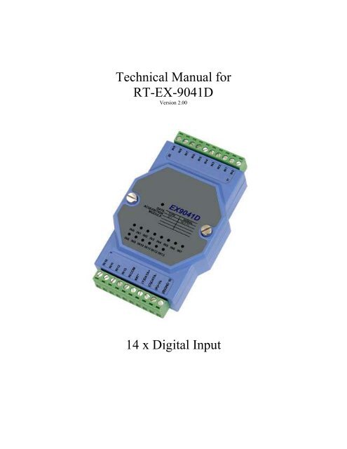
<strong>Technica</strong>l Manual for<strong>RT</strong>-<strong>EX</strong>-<strong>9041D</strong>Version 2.0014 x Digital Input
<strong>Technica</strong>l Manual, <strong>RT</strong>-<strong>EX</strong>-<strong>9041D</strong>, v2.00IntroductionThe <strong>EX</strong><strong>9041D</strong> MODBUS I/O Expansion module is a high-quality and low-cost add-on data acquisitiondevice that allows expanding the on-board digital input capabilities on X32-based <strong>RT</strong>CU units almostindefinitely and completely transparent using MODBUS communication protocol.The <strong>EX</strong><strong>9041D</strong> uses EIA RS-485 - the industry's most widely used bi-directional, balanced transmissionline standard. It lets the module transmit and receive data at high data rates over long distances.The <strong>EX</strong><strong>9041D</strong> can expand the <strong>RT</strong>CU with additional 14 digital inputs.The <strong>EX</strong><strong>9041D</strong> works in a variety of environments and applications, including: Factory automation and control SCADA applications HVAC applications Remote measuring, monitoring and control Security and alarm systems, etc.<strong>Logic</strong> <strong>IO</strong> ApS. Ph: (+45) 7625 0210Holmboes Allé 14 Fax: (+45) 7625 02118700 Horsens Email: info@logicio.comDenmarkWeb: www.logicio.comPage 2 of 10
<strong>Technica</strong>l Manual, <strong>RT</strong>-<strong>EX</strong>-<strong>9041D</strong>, v2.00Table of ContentsIntroduction ............................................................................................................................................. 2Table of Contents..................................................................................................................................... 3Graphical view......................................................................................................................................... 3Pin Assignment........................................................................................................................................ 4Default Settings ....................................................................................................................................... 5LED Indicator.......................................................................................................................................... 5INIT* Pin Operation (Configuration mode).............................................................................................. 6Wire Connections .................................................................................................................................... 7Open Collector signal input:................................................................................................................. 7TTL/CMOS signal input: ..................................................................................................................... 8Dry contact signal input: ...................................................................................................................... 8<strong>Technica</strong>l Specifications .......................................................................................................................... 9Appendix A – Using the module as I/O extension in the <strong>RT</strong>CU IDE...................................................... 10Graphical view<strong>Logic</strong> <strong>IO</strong> ApS. Ph: (+45) 7625 0210Holmboes Allé 14 Fax: (+45) 7625 02118700 Horsens Email: info@logicio.comDenmarkWeb: www.logicio.comPage 3 of 10
<strong>Technica</strong>l Manual, <strong>RT</strong>-<strong>EX</strong>-<strong>9041D</strong>, v2.00Pin AssignmentThe 2 x 10-pins plug-terminals as seen in the following figure allow connecting supply, communicationlines and digital inputs. The table below shows pin names and their function.Pin Name Description1 IN10 Digital input 102 IN11 Digital input 113 IN12 Digital input 124 IN13 Digital input 135 IN COM Digital common input6 INIT* Pin for initialization of the configuration routine7 (Y)DATA+ RS485+ data signal8 (G)DATA- RS485- data signal9 (R)+VS (+) Supply. Please refer to the specification for correct voltage level10 (B)GND Supply ground.<strong>Logic</strong> <strong>IO</strong> ApS. Ph: (+45) 7625 0210Holmboes Allé 14 Fax: (+45) 7625 02118700 Horsens Email: info@logicio.comDenmarkWeb: www.logicio.comPage 4 of 10
<strong>Technica</strong>l Manual, <strong>RT</strong>-<strong>EX</strong>-<strong>9041D</strong>, v2.00Pin Name Description11 IN0 Digital input 012 IN1 Digital input 113 IN2 Digital input 214 IN3 Digital input 315 IN4 Digital input 416 IN5 Digital input 517 IN6 Digital input 618 IN7 Digital input 719 IN8 Digital input 820 IN9 Digital input 9Please refer to the section ”Wire Connections” for correct wiring to the external device/sensor.Default SettingsNameDescriptionBaud rate 9600Data bits 8ParityNoneStop bit 1Device address 1These settings can easily be changed in <strong>RT</strong>CU IDE. Please refer to “Appendix A – Using the module asI/O extension in the <strong>RT</strong>CU IDE” for details.LED IndicatorThe <strong>EX</strong><strong>9041D</strong> is provided with a system LED to indicate power status and communication, and LEDs toindicate state of their respective inputs. In the following table description of the different states of theLEDs can be found:Name Pattern DescriptionSystemONPower onOFFPower offInputsONInput is HIGH*OFFInput is LOW*Please note that the inputs are internally pulled up, and will therefore appear high when not connected oridle.<strong>Logic</strong> <strong>IO</strong> ApS. Ph: (+45) 7625 0210Holmboes Allé 14 Fax: (+45) 7625 02118700 Horsens Email: info@logicio.comDenmarkWeb: www.logicio.comPage 5 of 10
<strong>Technica</strong>l Manual, <strong>RT</strong>-<strong>EX</strong>-<strong>9041D</strong>, v2.00INIT* Pin Operation (Configuration mode)The module has a build-in EEPROM to store configuration information such as address, type, baud rateand other information. Sometimes a user may forget the configuration of the module, or simply need tochange it. Therefore, the module has a special mode named "INIT mode" to allow the system to changethe configuration. To enable INIT mode, please follow these steps:1. Power off the module.2. Connect the INIT* pin to the GND pin.3. Power on the module.The module is now ready to be configured, afterward remove the power.When using the <strong>RT</strong>CU IDE to change the setting, select “setup module” from the right-click menu of thenode in “I/O – Extension” tree, and a guide will go through each step of the configuration process. Pleaserefer to the <strong>RT</strong>CU IDE on-line help for further information.<strong>Logic</strong> <strong>IO</strong> ApS. Ph: (+45) 7625 0210Holmboes Allé 14 Fax: (+45) 7625 02118700 Horsens Email: info@logicio.comDenmarkWeb: www.logicio.comPage 6 of 10
<strong>Technica</strong>l Manual, <strong>RT</strong>-<strong>EX</strong>-<strong>9041D</strong>, v2.00Wire ConnectionsOpen Collector signal input:When connecting open collector signals into the digital inputs please follow one of the wiring schemesbelow:IN14IN14<strong>Logic</strong> <strong>IO</strong> ApS. Ph: (+45) 7625 0210Holmboes Allé 14 Fax: (+45) 7625 02118700 Horsens Email: info@logicio.comDenmarkWeb: www.logicio.comPage 7 of 10
<strong>Technica</strong>l Manual, <strong>RT</strong>-<strong>EX</strong>-<strong>9041D</strong>, v2.00TTL/CMOS signal input:When connecting a device with TTL/CMOS outputs to the <strong>EX</strong><strong>9041D</strong> please follow the wiring scheme:IN14Dry contact signal input:When connecting dry contact signals to the input of the module please follow the wiring scheme below:IN4<strong>Logic</strong> <strong>IO</strong> ApS. Ph: (+45) 7625 0210Holmboes Allé 14 Fax: (+45) 7625 02118700 Horsens Email: info@logicio.comDenmarkWeb: www.logicio.comPage 8 of 10
<strong>Technica</strong>l Manual, <strong>RT</strong>-<strong>EX</strong>-<strong>9041D</strong>, v2.00<strong>Technica</strong>l Specifications<strong>Logic</strong> <strong>IO</strong> ApS. Ph: (+45) 7625 0210Holmboes Allé 14 Fax: (+45) 7625 02118700 Horsens Email: info@logicio.comDenmarkWeb: www.logicio.comPage 9 of 10
<strong>Technica</strong>l Manual, <strong>RT</strong>-<strong>EX</strong>-<strong>9041D</strong>, v2.00Appendix A – Using the module as I/O extension in the <strong>RT</strong>CU IDETo be able to use the MODBUS I/O Expansion module as an I/O extension, the <strong>RT</strong>CU IDE project needsto be configured correctly, by entering the correct parameters for the expansion module into the “I/OExtension device” dialog 1 .The following figure shows the correct setting for an <strong>EX</strong>9041 connected to the RS485_1 port on a <strong>RT</strong>CUDX4 with default settings:Default valueBased on<strong>RT</strong>CUDefault valuesMust matchthese valuesTo change the above mentioned default values, new values must be entered and transferred to themodule 2 .Values in the “I/O Extension net” must be set according to communication between the module and the<strong>RT</strong>CU unit, the port numeration follows the principles of the serOpen function, which is described in theIDE online help. When changing baud, data bit(s), parity or stop bit(s) all units on the net must bereconfigured 3 .The address field is per default “1”; if more modules are connected to same net each must have a uniqueaddress. Changing the address of a module is done, by selecting the new value and then reconfigure themodule.A close attention must be paid to the Count, Index in the Digital Inputs section, which must be 14 and 0respectively, else will communication with the module fail. Optional all readings can be inverted byselecting “Negate”1 Please refer to the <strong>RT</strong>CU IDE online help for creating and editing I/O extension2 Please see “Project Control - I/O Extension” in the IDE online help.3 To reconfigure: right click the device in the IDE and select “setup module”, and then follow the guide.<strong>Logic</strong> <strong>IO</strong> ApS. Ph: (+45) 7625 0210Holmboes Allé 14 Fax: (+45) 7625 02118700 Horsens Email: info@logicio.comDenmarkWeb: www.logicio.comPage 10 of 10