Technical documentation for RTCU-D4 - Logic IO
Technical documentation for RTCU-D4 - Logic IO
Technical documentation for RTCU-D4 - Logic IO

You also want an ePaper? Increase the reach of your titles
YUMPU automatically turns print PDFs into web optimized ePapers that Google loves.
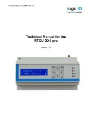
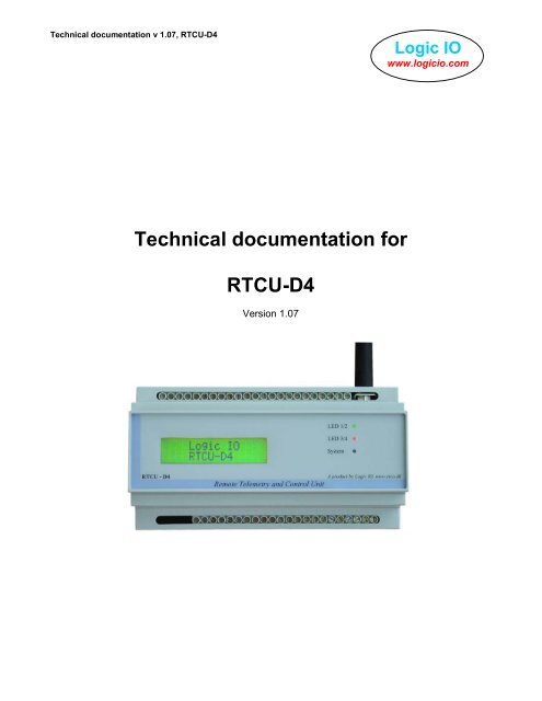
<strong>Technical</strong> <strong>documentation</strong> v 1.07, <strong>RTCU</strong>-<strong>D4</strong><strong>Logic</strong> <strong>IO</strong>www.logicio.com<strong>Technical</strong> <strong>documentation</strong> <strong>for</strong><strong>RTCU</strong>-<strong>D4</strong>Version 1.07
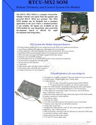
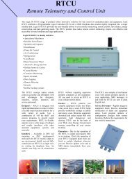
<strong>Technical</strong> <strong>documentation</strong> v 1.07, <strong>RTCU</strong>-<strong>D4</strong><strong>Logic</strong> <strong>IO</strong>www.logicio.comIntroductionThe <strong>RTCU</strong>-<strong>D4</strong> unit is an advanced unit in the <strong>RTCU</strong> product line with an impressive list offeatures and possibilities. The product is a unique combination of a powerful PLC and aGSM phone tightly connected in a single easy programmable unit. The <strong>RTCU</strong>-<strong>D4</strong> productprovides the user-friendly answer to your remote monitoring, remote control, surveillanceand datalogging needs.The <strong>RTCU</strong>-<strong>D4</strong> allows rapid development of custom specified applications combiningcontrol / monitoring / datalogging with advanced communication techniques such as voice/ DTMF interaction (voice response systems), alarm/messages send to / from the unit asSMS (both as SMS and PDU) messages or via data-transfer directly to / from Windowsapplications.This manual contains technical <strong>documentation</strong> allowing easy installation and use of theunit. For programming in<strong>for</strong>mation please consult the <strong>RTCU</strong> Programming Documentationand/or the <strong>RTCU</strong> IDE Online helpTable of Content:Introduction ......................................................................................................................... 2Table of Content:................................................................................................................. 2Graphical view..................................................................................................................... 3External connections........................................................................................................... 4Power supply................................................................................................................... 4Analog Inputs................................................................................................................... 4Analog outputs................................................................................................................. 5Digital Inputs.................................................................................................................... 5Digital outputs.................................................................................................................. 6Programming port (RS232) / RS485 port ........................................................................ 6Using the LCD-Display........................................................................................................ 7Contrast Adjustment ........................................................................................................ 7I/O Status Display............................................................................................................ 7Installing SIM card / connecting the GSM antenna ............................................................. 8SIM Card ......................................................................................................................... 8GSM Antenna .................................................................................................................. 8Switches / Indicators ........................................................................................................... 9Specifications .................................................................................................................... 10Page 2 of 10<strong>Logic</strong> <strong>IO</strong> ApS. Ph: (+45) 7625 0210Holmboes Allé 14 Fax: (+45) 7625 02118700 Horsens Email: info@logicio.comDenmarkwww.logicio.com / www.rtcu.dk
<strong>Technical</strong> <strong>documentation</strong> v 1.07, <strong>RTCU</strong>-<strong>D4</strong><strong>Logic</strong> <strong>IO</strong>www.logicio.comGraphical viewPin 1Page 3 of 10<strong>Logic</strong> <strong>IO</strong> ApS. Ph: (+45) 7625 0210Holmboes Allé 14 Fax: (+45) 7625 02118700 Horsens Email: info@logicio.comDenmarkwww.logicio.com / www.rtcu.dk
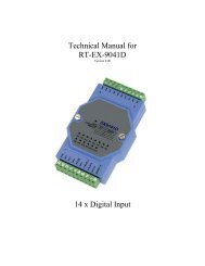
<strong>Technical</strong> <strong>documentation</strong> v 1.07, <strong>RTCU</strong>-<strong>D4</strong><strong>Logic</strong> <strong>IO</strong>www.logicio.comExternal connectionsAll connections to external equipment (except the GSM antenna) are done using screwterminals, located at the top and bottom of the unit (see graphical view). Each terminal isnumbered. The number is visible on the plastic top cover.Power supplyThe <strong>RTCU</strong>-<strong>D4</strong> unit must be supplied with a DC voltage between 8 and 36 Volt. Theconnections are as follows:8..36 VDC Supply:The 8..36 VDC supply is connected to the DCin and GND terminals on the unit (These arefound to the left, in the bottom row of screw terminals)Terminal Number DescriptionGND 5 Negative (-) connection from DC power supplyDCin 6 Positive (+) connection from DC power supplyGND 7 Negative (-) connection from DC power supplyAnalog InputsThe analog inputs are all voltage inputs, with a range from 0V to 5V DCThe input signal is connected between AIn and AGND. AGND must be connected to thereference of the connected equipment.Terminal Number DescriptionAGND 8 Analog groundAI1 9 Analog input number 1AI2 10 Analog input number 2AI3 11 Analog input number 3AI4 12 Analog input number 4AGND 13 Analog groundPage 4 of 10<strong>Logic</strong> <strong>IO</strong> ApS. Ph: (+45) 7625 0210Holmboes Allé 14 Fax: (+45) 7625 02118700 Horsens Email: info@logicio.comDenmarkwww.logicio.com / www.rtcu.dk
<strong>Technical</strong> <strong>documentation</strong> v 1.07, <strong>RTCU</strong>-<strong>D4</strong><strong>Logic</strong> <strong>IO</strong>www.logicio.comAnalog outputsLike the analog inputs, the analog outputs supports a voltage range of 0V to 5V DCThe output signal is taken from AOn and AGND. AGND must be connected to thereference of the connected equipment.Terminal Number DescriptionAO1 30 Analog output number 1AO2 31 Analog output number 2AO3 32 Analog output number 3AO4 33 Analog output number 4AGND 34 Analog groundDigital InputsThe digital inputs are galvanic isolated from the <strong>RTCU</strong> with optocouplers and they are alsolow-pass filtered and transient protected. For the inputs to be logical “high”, supply avoltage between the Din and DGND terminal, as per the requirements in the Specificationssection.Terminal Number DescriptionDGND 14 Digital input groundDI1 15 Digital input number 1DI2 16 Digital input number 2DI3 17 Digital input number 3DI4 18 Digital input number 4DI5 19 Digital input number 5DI6 20 Digital input number 6DI7 21 Digital input number 7DI8 22 Digital input number 8DI9 23 Digital input number 9DI10 24 Digital input number 10DI11 25 Digital input number 11DI12 26 Digital input number 12Page 5 of 10<strong>Logic</strong> <strong>IO</strong> ApS. Ph: (+45) 7625 0210Holmboes Allé 14 Fax: (+45) 7625 02118700 Horsens Email: info@logicio.comDenmarkwww.logicio.com / www.rtcu.dk
<strong>Technical</strong> <strong>documentation</strong> v 1.07, <strong>RTCU</strong>-<strong>D4</strong><strong>Logic</strong> <strong>IO</strong>www.logicio.comDigital outputsThe digital outputs interface to the outside world via solid-state drivers. The digital outputshave their own separate power supply terminal, and must be supplied with a voltagebetween 5 and 34 VDC to operate correctly.Terminal Number DescriptionDOSUPP 35 Digital output supplyDOSUPP 36 Digital output supplyDOSUPP 37 Digital output supplyDO1 38 Digital output number 1DO2 39 Digital output number 2DO3 40 Digital output number 3DO4 41 Digital output number 4DO5 42 Digital output number 5DO6 43 Digital output number 6DO7 44 Digital output number 7DO8 45 Digital output number 8DO9 46 Digital output number 9DO10 47 Digital output number 10DO11 48 Digital output number 11DO12 49 Digital output number 12Programming port (RS232) / RS485 portThe programming port (RS232) is shared with the RS485 port, if the RS485 port is used,the RS232 port cannot be used, and vice versa.The connection to the programming port (RS232) is done using the RJ11 connector in thelower left corner on the <strong>RTCU</strong> Unit (see graphical view)This connector can be used as a general-purpose serial port and as a programmingconnector. In order to use the connector as a programming connector, the RSDET pin (pin6) must be connected to GND. When using this connector as a general-purpose serialport, the RSDET pin must be left unconnected, or it can be tied to the VCC pin(recommended).Page 6 of 10<strong>Logic</strong> <strong>IO</strong> ApS. Ph: (+45) 7625 0210Holmboes Allé 14 Fax: (+45) 7625 02118700 Horsens Email: info@logicio.comDenmarkwww.logicio.com / www.rtcu.dk
<strong>Technical</strong> <strong>documentation</strong> v 1.07, <strong>RTCU</strong>-<strong>D4</strong><strong>Logic</strong> <strong>IO</strong>www.logicio.comProgramming port (RS232) / service port, RJ11 6 pin connector:Pin Name Description1 VCC +5V from <strong>RTCU</strong>. Normally unconnected.2 TxD RS232 Transmit data FROM <strong>RTCU</strong>3 GND Ground4 RxD RS232 Receive data TO <strong>RTCU</strong>5 NC Leave unconnected6 RSDET Programming cable detect, normally unconnected(if programming cable, connect to GND)The connection to the optional RS485 port is done using 3 screw terminals (see Graphicalview). The RS485 port is a multidrop port, with maximum 32 units connectedsimultaneously to the line. The RS485 connection contains the A (positive) and B(negative) signals, as well as a signal ground, which always needs to be connected to thecommon signal ground <strong>for</strong> all units connected to the RS485 bus! The maximum cablelength <strong>for</strong> the RS485 bus is approx 400 meters, however this limit can be influenced by thequality of the cable, signaling rate, noise etc.Terminal Number DescriptionRS485 B- 27 Negative wire <strong>for</strong> RS485 portRS485 A+ 28 Positive wire <strong>for</strong> RS485 portGND 29 Ground <strong>for</strong> RS485 portUsing the LCD-Display.The <strong>RTCU</strong>-<strong>D4</strong> includes as standard a LCD-Display with permanent backlighting. Thedisplay has 2 lines by 16 characters and can be accessed from the VPL program using thestandard display functions available. Please consult the <strong>RTCU</strong> IDE on-line help <strong>for</strong> morein<strong>for</strong>mation. The LCD-Display is connected to the “DISP1” connector with a flat cable onthe <strong>RTCU</strong> <strong>D4</strong> baseboard.Contrast AdjustmentIf the contrast of the display needs to be adjusted the small potentiometer (R95) locatedjust to the left of the display connector can be adjusted with a small screwdriver.I/O Status DisplayThe LCD-display will by default show the status of the analog and digital I/O of the unit.The display is used in the following way:Page 7 of 10<strong>Logic</strong> <strong>IO</strong> ApS. Ph: (+45) 7625 0210Holmboes Allé 14 Fax: (+45) 7625 02118700 Horsens Email: info@logicio.comDenmarkwww.logicio.com / www.rtcu.dk
<strong>Technical</strong> <strong>documentation</strong> v 1.07, <strong>RTCU</strong>-<strong>D4</strong><strong>Logic</strong> <strong>IO</strong>www.logicio.comLine 1:Line 2:1234567890ABCDEFGHIJKLMNOPQRSTUVLine 1 shows the status of the analog and digital outputs. 1,2,3,4 show the status of theanalog outputs using the 8 vertical lines of the character to show a scaled status of thefour analog outputs. 5,6,7,8,9,0,A,B,C,D,E,F shows the status of the 12 digital outputs innumerical order.Line 2 shows the status of the analog and digital inputs. G,H,I,J shows the status of theanalog inputs using the 8 vertical lines of the character to show a scaled status of the fouranalog inputs. K,L,M,N,O,P,Q,R,S,T,U,V shows the status of the 12 digital inputs innumerical order.The I/O Status Display will be continuously updated 2 times per second and will bedisabled totally when the VPL program running in the unit takes control and accesses thedisplay.Installing SIM card / connecting the GSM antennaSIM CardThe <strong>RTCU</strong> unit contains a standard SIM card reader. It is located to the lower left on theprinted circuit board, close to the edge. The SIM card reader is opened by carefullypressing down on the lid of the reader, and at the same time, pressing the lid towards thescrew terminals. It is then possible to open the SIM card reader, and insert your SIM cardinto it. Close the lid by pressing it down, while at the same time, pressing it towards theprogramming connector.GSM AntennaThe <strong>RTCU</strong> unit contains an SMA Female connector <strong>for</strong> connection of a suitable GSM Dualband antenna (900/1800 MHz). When installing the antenna, please make sure that theantenna is not in close proximity of metallic parts or anything else that can influence theefficiency of the GSM antenna. Please consult the installation guide that follows the GSMantenna.Page 8 of 10<strong>Logic</strong> <strong>IO</strong> ApS. Ph: (+45) 7625 0210Holmboes Allé 14 Fax: (+45) 7625 02118700 Horsens Email: info@logicio.comDenmarkwww.logicio.com / www.rtcu.dk
<strong>Technical</strong> <strong>documentation</strong> v 1.07, <strong>RTCU</strong>-<strong>D4</strong><strong>Logic</strong> <strong>IO</strong>www.logicio.comSwitches / IndicatorsA status indicator is present on the front of the unit (see the graphical view). Differentcolors/blinking patterns are used to signal different types of errors/status change in the<strong>RTCU</strong> unit:Fastest blinking, greenFast blinking, green (or yellow)Slow blinking; green (or yellow)Fast blinking, red (or yellow)Alternating Fast/Slow, red (or yellow)The unit is initializing, preparing to start the VPL programThe VPL program is not executing, stopped by thereset/diagnostic switch.The unit is executing the VPL programA runtime error has been detected in the programThe unit has lost its Firmware! This can only happen if,during a firmware upgrade, the <strong>RTCU</strong> Unit looses power, orthe communication is lost completely. In this case, simplyupload the firmware to the unit again.If the color of the status indicator is yellow, the unit is actively communicating with <strong>for</strong>example, the <strong>RTCU</strong>-IDE program (or another program, supporting the <strong>RTCU</strong> protocol,RACP).The <strong>RTCU</strong> unit contains a combined reset/diagnostic switch. This switch is located just tothe right of the two light pipes. When this switch is activated during reset of the unit (orpower on), the VPL program/project uploaded to the unit will not be started. The statusindicator indicates this. If the switch is activated <strong>for</strong> more than 3 seconds, the unit will reset(same as power on).Two-colored (red/green) indicators are visible above the status indicator. These indicatorscan be controlled from within the VPL program in the unit. The green part of the upper LEDis accessed as LED1 and the red part as LED2, and the green part of the lower LED isaccessed as LED3 and the red part as LE<strong>D4</strong>.The <strong>RTCU</strong> unit contains a dipswitch. The dipswitch is located near to upper row of screwterminals (see the graphical view). To use the dipswitch in the <strong>RTCU</strong>-IDE declare aBoolean input variable, and define it as a dipswitch in the <strong>RTCU</strong>-IDE Job variableconfiguration dialog.Page 9 of 10<strong>Logic</strong> <strong>IO</strong> ApS. Ph: (+45) 7625 0210Holmboes Allé 14 Fax: (+45) 7625 02118700 Horsens Email: info@logicio.comDenmarkwww.logicio.com / www.rtcu.dk
<strong>Technical</strong> <strong>documentation</strong> v 1.07, <strong>RTCU</strong>-<strong>D4</strong><strong>Logic</strong> <strong>IO</strong>www.logicio.comSpecificationsAnalog inputsMinMax0-+5VDCResolution is 10 bits. All inputs are protectedagainst transients and lowpass filtered.Analog outputsMinMax0-+5VDCResolution is 10 bits. All outputs are protectedagainst transients and lowpass filtered.Digital inputsMinTypMax<strong>Logic</strong> ”High”<strong>Logic</strong> ”Low”8-510-405VDCVDCAll inputs are protected against transients andlowpass filteredDigital outputsMinTypMax5-34VDCAll outputs are protected against short-circuit.--1000mAPower supplyMinTypMaxOperating Voltage8-36VDCProtected againts wrong polarity, self healingfuseUnit Active with GSM offUnit Active with GSM onUnit in Sleep with GSM off758050150mAmAmAAt 24 VDC supply voltageStorage temperature-40-+90ºCFor mounting on standard DIN rail (EN50022).Operating temperature(According to GSM 11.10 specification)Restricted operation(deviations from the GSM specification may occur)-20-29--+55+70ºCºCSMA-Female connector <strong>for</strong> Dual band(900/1800 MHz) GSM antenna.Humidity (non condensing)5-90%Weight0.3KgExternal dimensionsIngress Protection (IP)Approvals<strong>Technical</strong> data subject to changeW 157 x H 86 x D 58 mmIP20EN-50081-1 EmissionEN-61000-6-2 ImmunityStandard M36 DIN enclosureUnit is CE ApprovedPage 10 of 10<strong>Logic</strong> <strong>IO</strong> ApS. Ph: (+45) 7625 0210Holmboes Allé 14 Fax: (+45) 7625 02118700 Horsens Email: info@logicio.comDenmarkwww.logicio.com / www.rtcu.dk