Technical Manual for the RTCU MX2i eco - Logic IO
Technical Manual for the RTCU MX2i eco - Logic IO
Technical Manual for the RTCU MX2i eco - Logic IO

Create successful ePaper yourself
Turn your PDF publications into a flip-book with our unique Google optimized e-Paper software.
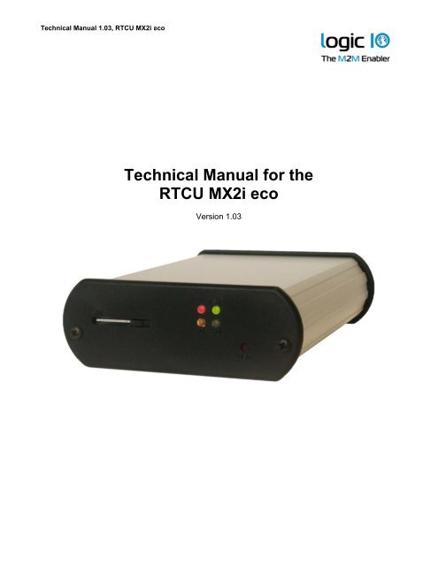
<strong>Technical</strong> <strong>Manual</strong> 1.03, <strong>RTCU</strong> <strong>MX2i</strong> <strong>eco</strong><strong>Technical</strong> <strong>Manual</strong> <strong>for</strong> <strong>the</strong><strong>RTCU</strong> <strong>MX2i</strong> <strong>eco</strong>Version 1.03
<strong>Technical</strong> <strong>Manual</strong> 1.03, <strong>RTCU</strong> <strong>MX2i</strong> <strong>eco</strong>IntroductionThis manual contains technical documentation allowing easy installation and use of <strong>the</strong><strong>RTCU</strong> <strong>MX2i</strong> <strong>eco</strong> unit. For in<strong>for</strong>mation on <strong>the</strong> programming and software configuration of<strong>the</strong> <strong>RTCU</strong> <strong>MX2i</strong> <strong>eco</strong> please refer to <strong>the</strong> <strong>RTCU</strong> IDE documentation.The <strong>RTCU</strong> <strong>MX2i</strong> <strong>eco</strong> is <strong>the</strong> s<strong>eco</strong>nd member belonging to <strong>the</strong> new MX generation ofpowerful <strong>RTCU</strong> units. The unit is a low cost version of <strong>the</strong> popular <strong>RTCU</strong>-<strong>MX2i</strong> PRO. Witha reduced feature set compared to <strong>the</strong> <strong>RTCU</strong>-<strong>MX2i</strong> PRO <strong>the</strong> product has a perfectbalance between price and per<strong>for</strong>mance. The price-level of <strong>the</strong> <strong>RTCU</strong> <strong>MX2i</strong> <strong>eco</strong> belongs to<strong>the</strong> entry-level segment, but <strong>the</strong> advanced features are in a league of its own!The unit has an impressive list of features including full support <strong>for</strong> GPRS, SMS and Datacalls. The unit is especially suited <strong>for</strong> mobile tracking applications with its onboard GPSreceiverand advanced power management features. The unit is fully supported by <strong>the</strong><strong>RTCU</strong> IDE development tool and is fully backward compatible with previous generation of<strong>RTCU</strong> units.The advanced power-management features on <strong>the</strong> <strong>RTCU</strong> <strong>MX2i</strong> <strong>eco</strong> allows <strong>the</strong> unit to stayin power-saving modes <strong>for</strong> a longer period of time still being connected to <strong>the</strong> GSMnetwork and capable of waking up on <strong>for</strong> example GSM activity, change of digital inputs ora vibration sensor!These features open up <strong>for</strong> <strong>the</strong> use of <strong>the</strong> <strong>RTCU</strong> <strong>MX2i</strong> <strong>eco</strong> in exciting new applicationareas where extremely low power consumption and flexible wake-up conditions are acrucial parameter <strong>for</strong> successful product integration.Page 2 of 18<strong>Logic</strong> <strong>IO</strong> ApS. Ph: (+45) 7625 0210Holmboes Allé 14 Fax: (+45) 7625 02118700 Horsens Email: info@logicio.comDenmarkwww.logicio.com / www.rtcu.dk
<strong>Technical</strong> <strong>Manual</strong> 1.03, <strong>RTCU</strong> <strong>MX2i</strong> <strong>eco</strong>Table of ContentsIntroduction ..........................................................................................................................2Table of Contents ................................................................................................................3Graphical view .....................................................................................................................4External connections............................................................................................................5Overview ..........................................................................................................................5Power supply....................................................................................................................8Digital outputs ..................................................................................................................9Digital Inputs / Ignition Input ...........................................................................................10Serial port 1 / Programming port. ...................................................................................11DC-Out ...........................................................................................................................11Vibration Sensor ................................................................................................................11Indicators (LED’s) ..............................................................................................................12System Switch (RST).........................................................................................................13Installing <strong>the</strong> SIM-card .......................................................................................................14Antennas............................................................................................................................15GSM...............................................................................................................................15GPS................................................................................................................................15Barcode .............................................................................................................................15Power consumption ...........................................................................................................16Specifications <strong>for</strong> <strong>the</strong> <strong>RTCU</strong> <strong>MX2i</strong> <strong>eco</strong>...............................................................................17Specifications <strong>for</strong> <strong>the</strong> 16-channel GPS receiver.................................................................18Page 3 of 18<strong>Logic</strong> <strong>IO</strong> ApS. Ph: (+45) 7625 0210Holmboes Allé 14 Fax: (+45) 7625 02118700 Horsens Email: info@logicio.comDenmarkwww.logicio.com / www.rtcu.dk
<strong>Technical</strong> <strong>Manual</strong> 1.03, <strong>RTCU</strong> <strong>MX2i</strong> <strong>eco</strong>Graphical viewPage 4 of 18<strong>Logic</strong> <strong>IO</strong> ApS. Ph: (+45) 7625 0210Holmboes Allé 14 Fax: (+45) 7625 02118700 Horsens Email: info@logicio.comDenmarkwww.logicio.com / www.rtcu.dk
<strong>Technical</strong> <strong>Manual</strong> 1.03, <strong>RTCU</strong> <strong>MX2i</strong> <strong>eco</strong>Connector X1: 4 pin PWR connector overview.Pin Name Description1 SUPP Power Supply, positive (+) connection2 DI5/IGN Digital Input 5 / Ignition Input (Shared with 16 pin connector)3 SUPP Power Supply, positive (+) connection4 PGND Power GroundConnector X3: 16 pin I/O connector overview.Pin Name Description1 DOUT 1 Digital Output 12 DOUT 3 Digital Output 33 DIN 1 Digital Input 14 SGND Signal Ground5 DIN 3 Digital Input 36 DIN 5/IGN Digital Input 5 / Ignition Input (Shared with 4 pin connector)7 N.C Not Connected8 N.C Not Connected9 DOUT 2 Digital Output 210 DOUT 4 Digital Output 411 DIN 2 Digital Input 212 SGND Signal Ground13 DIN 4 Digital Input 414 SGND Signal Ground15 AGND Analog Ground16 AGND Analog GroundConnector X4: 6 pin SER1 connector overview.Pin Name Description1 TD Transmit Data from serial port 1, RS232 compatible2 RS-DET Programming cable detect, normally unconnected (if programmingcable, connect to GND)3 DC-Out +3.3V/150mA DC-Out <strong>for</strong> external equipment.4 RD Receive Data <strong>for</strong> serial port 1, RS232 compatible5 SGND Signal Ground6 SGND Signal GroundPage 6 of 18<strong>Logic</strong> <strong>IO</strong> ApS. Ph: (+45) 7625 0210Holmboes Allé 14 Fax: (+45) 7625 02118700 Horsens Email: info@logicio.comDenmarkwww.logicio.com / www.rtcu.dk
<strong>Technical</strong> <strong>Manual</strong> 1.03, <strong>RTCU</strong> <strong>MX2i</strong> <strong>eco</strong>Accessories available from <strong>Logic</strong> <strong>IO</strong> <strong>for</strong> cable assembly.Order-code NameTYCO, Connector house 4 pins. Bag with 10 pcsRT-O-TYCO-H4TYCO p/n: 794617-4RT-O-TYCO-H6TYCO p/n: 794617-6RT-O-TYCO-H16TYCO p/n: 1-794617-6RT-O-TYCO-CRTYCO p/n: 794606-1RT-O-TYCO-TOOLTYCO p/n: 91501-1R<strong>eco</strong>mmended tool:TYCO, Connector house 6 pins. Bag with 10 pcsTYCO, Connector house 16 pins. Bag with 10 pcsTYCO, Crimp Contacts <strong>for</strong> connector house. Wire size 0.2 to 0.5mm 2 . Bag with 100 pcs.TYCO, Crimp hand tool <strong>for</strong> easy assembly of TYCO crimp contacts.Wire size 0.2 to 0.5 mm 2Tyco 91501-1 (0.20 to 0.50mm 2 ) RS 495-9675, Farnell 1111475Alternative tools: Tyco 91502-1 (0.05 to 0.15mm 2 ) RS 495-9675, Farnell 1111476Molex 69008-0982 (0.20 to 0.50mm 2 ) RS 233-3059, Farnell 673122Molex 69008-0983 (0.05 to 0.05mm 2 ) RS 233-3065, Farnell 673134Extraction tool: Tyco 843996-6 extraction tool. RS 495-9704, Farnell 1111477Page 7 of 18<strong>Logic</strong> <strong>IO</strong> ApS. Ph: (+45) 7625 0210Holmboes Allé 14 Fax: (+45) 7625 02118700 Horsens Email: info@logicio.comDenmarkwww.logicio.com / www.rtcu.dk
<strong>Technical</strong> <strong>Manual</strong> 1.03, <strong>RTCU</strong> <strong>MX2i</strong> <strong>eco</strong>Power supplyThe <strong>RTCU</strong> <strong>MX2i</strong> <strong>eco</strong> unit is to be supplied with 8...36 VDC from an external DC powersource connected to <strong>the</strong> 4 pin power connector. Positive power is applied to <strong>the</strong> SUPP pinand ground is connected to <strong>the</strong> PGND pin.The connector has two “SUPP” supply pins as <strong>the</strong>se also supplies power <strong>for</strong> <strong>the</strong> DigitalOutputs. If <strong>the</strong> total current consumption on <strong>the</strong> digital outputs exceeds 1.5A <strong>the</strong>n powermust be applied to both pins. O<strong>the</strong>rwise one pin would be sufficient.There are three different labels <strong>for</strong> <strong>the</strong> ground connections: Power Ground (PGND), SignalGround (SGND) and Analog Ground (AGND). The signal and analog grounds are filteredfrom <strong>the</strong> power ground. Power ground must only be used as power supply return path. Thesignal ground is used as ground reference <strong>for</strong> digital I/O’s and serial interfaces. And <strong>the</strong>analog ground is used as a low noise analog ground reference <strong>for</strong> <strong>the</strong> analog inputs.The <strong>RTCU</strong> <strong>MX2i</strong> <strong>eco</strong> is protected against wrong polarity. If a chassis or system groundsare connected to ei<strong>the</strong>r SGND or AGND a wrong polarity on <strong>the</strong> supply lines will destroy<strong>the</strong> internal GND connection. For avoidance of such a scenario a fuse can be installed on<strong>the</strong> positive supply.When <strong>the</strong> ignition input is activated with a logical high, <strong>the</strong> <strong>RTCU</strong> unit will wake-up if it wasin power down mode. The ignition input (digital input 5) is available on <strong>the</strong> powerconnector to minimize <strong>the</strong> need <strong>for</strong> connectors in minimal connector installations, but it isalso available on <strong>the</strong> 16 pin connector (Digital I/O) - only one should be used at a time.Please note: When external power is removed from <strong>the</strong> unit <strong>the</strong> Real Time Clock (RTC)looses <strong>the</strong> time.X1: 4 pin PWR connector overview.Pin Name Description1 SUPP Power Supply, positive (+) connection2 DI5/IGN Digital Input 5 / Ignition input (Shared with 16 pin connector)3 SUPP Power Supply, positive (+) connection4 PGND Power GroundPage 8 of 18<strong>Logic</strong> <strong>IO</strong> ApS. Ph: (+45) 7625 0210Holmboes Allé 14 Fax: (+45) 7625 02118700 Horsens Email: info@logicio.comDenmarkwww.logicio.com / www.rtcu.dk
<strong>Technical</strong> <strong>Manual</strong> 1.03, <strong>RTCU</strong> <strong>MX2i</strong> <strong>eco</strong>Digital outputsThe digital outputs control four “high-side” switches. They function like a contact, whereone side is connected to <strong>the</strong> positive supply of <strong>the</strong> <strong>RTCU</strong> unit, and <strong>the</strong> o<strong>the</strong>r is <strong>the</strong> output.The switches are protected against short circuit, ESD and electronic kickback frominductive loads such as relays etc. The maximum switch-able inductance is 20mH andmust not be exceeded.The digital outputs are supplied through <strong>the</strong> 4 pin power connector, which also supplies<strong>the</strong> rest of <strong>the</strong> <strong>RTCU</strong> unit. As <strong>the</strong> power is also <strong>the</strong> <strong>RTCU</strong> <strong>MX2i</strong> <strong>eco</strong> main power, a powerfailwould also affect <strong>the</strong> digital outputs.The <strong>RTCU</strong> unit offers a very advanced power management, which makes it possible tohave one or more outputs enabled while <strong>the</strong> <strong>RTCU</strong> is in low power mode. Please consult<strong>the</strong> <strong>RTCU</strong>-IDE online help <strong>for</strong> more in<strong>for</strong>mation.Please note: Special attention to wiring must be taken; if <strong>the</strong> total current consumption of<strong>the</strong> digital outputs exceeds 1.5A <strong>the</strong>n PGND must be used as return path <strong>for</strong> <strong>the</strong> output(s).If <strong>the</strong> total current consumption of <strong>the</strong> digital outputs exceeds 5A <strong>the</strong> two SUPP pins andPGND must be used <strong>for</strong> supply.X3: 16 pin I/O connector overview.Pin Name Description1 DOUT 1 Digital Output 19 DOUT 2 Digital Output 22 DOUT 3 Digital Output 310 DOUT 4 Digital Output 4Page 9 of 18<strong>Logic</strong> <strong>IO</strong> ApS. Ph: (+45) 7625 0210Holmboes Allé 14 Fax: (+45) 7625 02118700 Horsens Email: info@logicio.comDenmarkwww.logicio.com / www.rtcu.dk
<strong>Technical</strong> <strong>Manual</strong> 1.03, <strong>RTCU</strong> <strong>MX2i</strong> <strong>eco</strong>Digital Inputs / Ignition InputThe digital inputs are all low-pass filtered and transient protected. To activate <strong>the</strong> inputs,connect a positive voltage between <strong>the</strong> input and <strong>the</strong> GND connector.Please note: The DIN 5/IGN input is a special input as it also functions as <strong>the</strong> ignitioninput. If <strong>the</strong> ignition input is activated with a logical high or low (Wait For Event mode only)when <strong>the</strong> <strong>RTCU</strong> is in low power mode, it will wake-up <strong>the</strong> unit. A power apply will alsowake-up <strong>the</strong> unit if it is in power-down mode or WaitForEvent mode with power Applyand/or ignition selected <strong>for</strong> wake-up. The ignition is de-bounced with a period between 1-2ms when used as a digital input. So any logical level applied to this input must be greaterthan 2 ms to be valid. The DIN 5/IGN input is available on both <strong>the</strong> 4 pin power connectorand <strong>the</strong>16 pin connector toge<strong>the</strong>r with <strong>the</strong> o<strong>the</strong>r digital inputs – only one should be used ata time.The power management allows <strong>the</strong> possibility to configure a wake-up on one or moredigital inputs with individually configured falling- or rising edge detection. Please consult<strong>the</strong> <strong>RTCU</strong>-IDE online help <strong>for</strong> more in<strong>for</strong>mation.X3: 16 pin I/O connector overview.Pin Name Description3 DIN 1 Digital Input 111 DIN 2 Digital Input 25 DIN 3 Digital Input 313 DIN 4 Digital Input 46 DIN 5/IGN Digital Input 5 / Ignition Input. (Shared with 4 pin connector)4 SGND Signal Ground10 SGND Signal Ground14 SGND Signal GroundPage 10 of 18<strong>Logic</strong> <strong>IO</strong> ApS. Ph: (+45) 7625 0210Holmboes Allé 14 Fax: (+45) 7625 02118700 Horsens Email: info@logicio.comDenmarkwww.logicio.com / www.rtcu.dk
<strong>Technical</strong> <strong>Manual</strong> 1.03, <strong>RTCU</strong> <strong>MX2i</strong> <strong>eco</strong>Serial port 1 / Programming port.This port can be used as general-purpose RS232 serial port or as a programming port. Inorder to use <strong>the</strong> port <strong>for</strong> programming, <strong>the</strong> RS-DET pin must be connected to GND. Whenusing <strong>the</strong> port as general-purpose RS232, <strong>the</strong> RS-DET pin must be left unconnected.Fur<strong>the</strong>r details on <strong>the</strong> programming cable are available in <strong>the</strong> <strong>RTCU</strong>-IDE online help.X4: 6 pin SER1 connector overview.Pin Name Description1 TD Transmit Data from serial port 1, RS232 compatible4 RD Receive Data <strong>for</strong> serial port 1, RS232 compatible2 RS-DET Programming cable detect, normally unconnected (if programmingcable, connect to GND)5 SGND Signal GroundDC-OutA 3.3VDC output is available on <strong>the</strong> 6 pin serial port 1 connector. It is possible to control<strong>the</strong> output in order to save power. The output is short circuit- (to ground), ESD- andtransient protected.Make sure not exceed <strong>the</strong> current specification of <strong>the</strong> output and be aware of inrushcurrents of <strong>the</strong> external equipment may exceed <strong>the</strong> specifications. It is r<strong>eco</strong>mmended toinstall a fuse to protect <strong>the</strong> output.This output must be enabled from <strong>the</strong> application. Please consult <strong>the</strong> <strong>RTCU</strong>-IDE onlinemanual <strong>for</strong> more in<strong>for</strong>mation.X4: 6 pin SER1 connector overview.Pin Name Description3 DC-Out +3.3V/150mA DC-Out <strong>for</strong> external equipment.5 SGND Signal GroundVibration SensorThe <strong>RTCU</strong> <strong>MX2i</strong> <strong>eco</strong> unit contains a vibration sensor. It makes it possible through <strong>the</strong>power management to detect vibrations when <strong>for</strong> example <strong>the</strong> vehicle is moved. Thesensitivity can be altered from within <strong>the</strong> VPL program - making it suitable <strong>for</strong> variousapplications. Please consult <strong>the</strong> <strong>RTCU</strong>-IDE online manual <strong>for</strong> more in<strong>for</strong>mation.Page 11 of 18<strong>Logic</strong> <strong>IO</strong> ApS. Ph: (+45) 7625 0210Holmboes Allé 14 Fax: (+45) 7625 02118700 Horsens Email: info@logicio.comDenmarkwww.logicio.com / www.rtcu.dk
<strong>Technical</strong> <strong>Manual</strong> 1.03, <strong>RTCU</strong> <strong>MX2i</strong> <strong>eco</strong>Indicators (LED’s)Three bi-colored (red and green) and a single yellow LED indicators are present on <strong>the</strong>front of <strong>the</strong> unit (see <strong>the</strong> graphical view). Two bi-colored LED’s (A and B) are available to<strong>the</strong> user and <strong>the</strong> remaining two LED’s (S1 and S2) are signaling <strong>the</strong> status and possibleerrors of <strong>the</strong> <strong>RTCU</strong> unit.The user control LED one through four <strong>for</strong> application specific signaling purposes.• LED named A on <strong>the</strong> front-plate, consists of LED 1 (green) and LED 2 (red)• LED named B on <strong>the</strong> front-plate, consists of LED 3 (green) and LED 4 (red)They are easily accessed from within <strong>the</strong> VPL program, and it is possible to mix <strong>the</strong> LED’sto obtain a third color, yellow. Please consult <strong>the</strong> <strong>RTCU</strong>-IDE online manual <strong>for</strong> morein<strong>for</strong>mation.The remaining two LED’s a used by <strong>the</strong> <strong>RTCU</strong> to signal <strong>the</strong> status of <strong>the</strong> unit. The differentpatterns are listed in <strong>the</strong> table below. If <strong>the</strong> color of <strong>the</strong> S1 is yellow, <strong>the</strong> unit is activelycommunicating with <strong>for</strong> example <strong>the</strong> <strong>RTCU</strong>-IDE program (or ano<strong>the</strong>r program, supporting<strong>the</strong> <strong>RTCU</strong> protocol, RACP).S1: System LED1 pattern overview.PatternDescriptionFastest blinking, greenThe unit is initializing, preparing to start <strong>the</strong> VPLprogramFast blinking, green (or yellow) The VPL program is not executing, but stopped by <strong>the</strong>reset/diagnostic switch.500ms On / 500ms OffThe unit is executing <strong>the</strong> VPL programgreen (or yellow)1.5s On / 0.5s Off.The unit is executing <strong>the</strong> VPL program and charging <strong>the</strong>green (or yellow)internal back-up battery.Fast blinking, red (or yellow) A runtime error has been detected in <strong>the</strong> program. Use<strong>the</strong> <strong>RTCU</strong> IDE to obtain <strong>the</strong> fault log.Alternating Fast/Slow, red (or The unit has lost its Firmware! This can only happen if,yellow)during a firmware upgrade, <strong>the</strong> <strong>RTCU</strong> Unit loosespower, or <strong>the</strong> communication is lost completely. In thiscase, simply upload <strong>the</strong> firmware to <strong>the</strong> unit again.75ms On / 925ms OffExecution speed is different from full-speed.The single yellow LED is signaling ei<strong>the</strong>r <strong>the</strong> GSM module activity or if all o<strong>the</strong>r LED’s areoff it will signal that <strong>the</strong> <strong>RTCU</strong> is in <strong>the</strong> “wait <strong>for</strong> event” low power state. Please see <strong>the</strong>table below:Page 12 of 18<strong>Logic</strong> <strong>IO</strong> ApS. Ph: (+45) 7625 0210Holmboes Allé 14 Fax: (+45) 7625 02118700 Horsens Email: info@logicio.comDenmarkwww.logicio.com / www.rtcu.dk
<strong>Technical</strong> <strong>Manual</strong> 1.03, <strong>RTCU</strong> <strong>MX2i</strong> <strong>eco</strong>S2: System LED2 pattern overview (GSM activity and “Wait For Event”).PatternOperating StatusOffThe GSM module is turned off600 ms On / 600 ms Off No SIM card inserted or no PIN code entered, ornetwork search in progress, or ongoing userau<strong>the</strong>ntication, or network logon in progress.75 ms On / 3 s Off Logged to <strong>the</strong> network.No call in progress.75 ms On / 75 ms Off /A GPRS session is active75 ms On / 3 s OFFFlashingIndicates GPRS data transfer.OnDepending on type of call:Voice call: Connected to remote party.Data call: Connected to remote party or exchange ofparameters while setting up or disconnecting a call.8 s OFF / 10 ms ON The <strong>RTCU</strong> unit is in “Wait For Event” low power state.System Switch (RST)The <strong>RTCU</strong> <strong>MX2i</strong> <strong>eco</strong> unit contains a combined reset/diagnostic switch. This switch islocated on <strong>the</strong> front-plate of <strong>the</strong> <strong>RTCU</strong> unit (see <strong>the</strong> graphical view).By activating <strong>the</strong> switch shortly <strong>the</strong> <strong>RTCU</strong> unit will do a complete reset, as if <strong>the</strong> power wasremoved and reapplied. If <strong>the</strong> reset switch is held down <strong>for</strong> approx. 3 s<strong>eco</strong>nds 1 <strong>the</strong> VPLprogram present in <strong>the</strong> unit will not be started and <strong>the</strong> unit will turn on <strong>the</strong> GSM moduleand establish connection to <strong>the</strong> GSM network and to GPRS / Gateway (if configured). Thismethod will also activate <strong>the</strong> unit if it is powered down due to a power fail. The feature isvery helpful when maintenance without power is needed. To “exit” (power down <strong>the</strong> unitagain) from this mode simply activate <strong>the</strong> reset switch shortly.The status indicator indicates <strong>the</strong> state by fast blinking green or yellow as stated above.1 System LED S2 will flash three times when this state is entered.Page 13 of 18<strong>Logic</strong> <strong>IO</strong> ApS. Ph: (+45) 7625 0210Holmboes Allé 14 Fax: (+45) 7625 02118700 Horsens Email: info@logicio.comDenmarkwww.logicio.com / www.rtcu.dk
<strong>Technical</strong> <strong>Manual</strong> 1.03, <strong>RTCU</strong> <strong>MX2i</strong> <strong>eco</strong>Installing <strong>the</strong> SIM-cardThe <strong>RTCU</strong> <strong>MX2i</strong> <strong>eco</strong> unit contains a standard SIM card reader. It is located on <strong>the</strong> frontplate (see <strong>the</strong> graphical view) and is easily accessed. The SIM card reader has apush/push eject system and a mechanical lock <strong>for</strong> secure installation of <strong>the</strong> SIM card.Orientate <strong>the</strong> card as showed below, and insert it into <strong>the</strong> card reader. Push <strong>the</strong> card into<strong>the</strong> reader until a click sound occurs – <strong>the</strong> card will now stay in its position. It might benecessary to use a small tool or pencil as <strong>the</strong> card, <strong>for</strong> protection purposes, is placedunderneath <strong>the</strong> front-plate surface. Fur<strong>the</strong>rmore a mechanical lock can be slide in front of<strong>the</strong> card to prevent it from being removed accidentally.To remove <strong>the</strong> card slide <strong>the</strong> lock to its unlocked position, and push <strong>the</strong> card into <strong>the</strong>reader until a small click sound occurs. The reader will now eject <strong>the</strong> card. It might benecessary to use a small tool or pencil to push <strong>the</strong> card into <strong>the</strong> reader.It is possible to detect <strong>the</strong> state of both <strong>the</strong> SIM Insert and SIM lock status from <strong>the</strong> VPLprogram. Please consult <strong>the</strong> <strong>RTCU</strong>-IDE online manual <strong>for</strong> more in<strong>for</strong>mation.SIM card Orientation.If <strong>the</strong> SIM-card is removed during GSM operation <strong>the</strong> unit will shortly after be rejected from<strong>the</strong> GSM network. When a SIM-card is inserted again <strong>the</strong> unit will automatically resetapprox. 10 s<strong>eco</strong>nds after insertion and <strong>the</strong>n commence normal operation.Page 14 of 18<strong>Logic</strong> <strong>IO</strong> ApS. Ph: (+45) 7625 0210Holmboes Allé 14 Fax: (+45) 7625 02118700 Horsens Email: info@logicio.comDenmarkwww.logicio.com / www.rtcu.dk
<strong>Technical</strong> <strong>Manual</strong> 1.03, <strong>RTCU</strong> <strong>MX2i</strong> <strong>eco</strong>AntennasGSMThe <strong>RTCU</strong> <strong>MX2i</strong> <strong>eco</strong> unit contains an SMA Female connector <strong>for</strong> connection of a suitableGSM quad band antenna (850/900/1800/1900 MHz). When installing <strong>the</strong> antenna, pleasemake sure that <strong>the</strong> antenna is not in close proximity of metallic parts or anything else thatcan influence <strong>the</strong> efficiency of <strong>the</strong> GSM antenna. Please consult <strong>the</strong> installation guide thatfollows <strong>the</strong> GSM antenna.GPSThe <strong>RTCU</strong> <strong>MX2i</strong> <strong>eco</strong> unit contains an SMB Male connector <strong>for</strong> connection of a suitableGPS antenna. The GPS antenna must be a 3V active GPS antenna mounted with a SMBFemale connector.When installing <strong>the</strong> antenna, please make sure that <strong>the</strong> antenna has a reasonable view of<strong>the</strong> sky so that it can receive <strong>the</strong> weak signals from <strong>the</strong> satellites. Please also consult <strong>the</strong>installation guide that follows <strong>the</strong> GPS antenna.BarcodeThe barcode found on <strong>the</strong> <strong>MX2i</strong> unit contains <strong>the</strong> serial number.The first eight digits in <strong>the</strong> barcode is <strong>Logic</strong> <strong>IO</strong> specific.The barcode <strong>for</strong>mat is:• 2/5 Interleaved with Check DigitPage 15 of 18<strong>Logic</strong> <strong>IO</strong> ApS. Ph: (+45) 7625 0210Holmboes Allé 14 Fax: (+45) 7625 02118700 Horsens Email: info@logicio.comDenmarkwww.logicio.com / www.rtcu.dk
<strong>Technical</strong> <strong>Manual</strong> 1.03, <strong>RTCU</strong> <strong>MX2i</strong> <strong>eco</strong>Power consumptionDetailed in<strong>for</strong>mation on <strong>the</strong> maximum power consumption of <strong>the</strong> <strong>MX2i</strong> unit in differentstates and at different supply voltages is listed below.Maximum power consumption: Unit running on external supply.8V 12V 36VUnit Active 60 45 20 mAUnit Active with GSM On 90 50 25 mA GSM idle @ -63dBmUnit active with GPS On 90 65 25 mAUnit Active with GSM/GPS On 115 75 30 mA GSM idle @ -63dBmUnit in power-down 0.4 0.3 0.2 mA Resume on DI5, <strong>RTCU</strong>nit in “wait <strong>for</strong> event” 0.6 0.4 0.2 mA Resume on DI, Vibration, <strong>RTCU</strong>nit in “wait <strong>for</strong> event” 10 7 3 mA Resume on RS232Unit in “wait <strong>for</strong> event” 20 15 6 mA Resume on GSM activityPage 16 of 18<strong>Logic</strong> <strong>IO</strong> ApS. Ph: (+45) 7625 0210Holmboes Allé 14 Fax: (+45) 7625 02118700 Horsens Email: info@logicio.comDenmarkwww.logicio.com / www.rtcu.dk
<strong>Technical</strong> <strong>Manual</strong> 1.03, <strong>RTCU</strong> <strong>MX2i</strong> <strong>eco</strong>Specifications <strong>for</strong> <strong>the</strong> <strong>RTCU</strong> <strong>MX2i</strong> <strong>eco</strong><strong>Technical</strong> data subject to changePage 17 of 18<strong>Logic</strong> <strong>IO</strong> ApS. Ph: (+45) 7625 0210Holmboes Allé 14 Fax: (+45) 7625 02118700 Horsens Email: info@logicio.comDenmarkwww.logicio.com / www.rtcu.dk
<strong>Technical</strong> <strong>Manual</strong> 1.03, <strong>RTCU</strong> <strong>MX2i</strong> <strong>eco</strong>Specifications <strong>for</strong> <strong>the</strong> 16-channel GPS receiveru-blox LEA-4AGeneral:Update Rate:16 Channels simultaneous operationDGPS and A-GPS capableL1 frequency (1575.42MHz)C/A code (Standard Positioning Service)Continuous tracking receiverNMEA @ 1 HzAccuracy: Position 2.5m CEPDGPS/SBAS 2.5m CEP 2Acquisition:Interface protocol:Autonomous Operation in Standard Sensitivity ModeReacquisition