Automatic Swing Door Operator DFA 127 Operating instructions E
Automatic Swing Door Operator DFA 127 Operating instructions E
Automatic Swing Door Operator DFA 127 Operating instructions E
- No tags were found...

You also want an ePaper? Increase the reach of your titles
YUMPU automatically turns print PDFs into web optimized ePapers that Google loves.
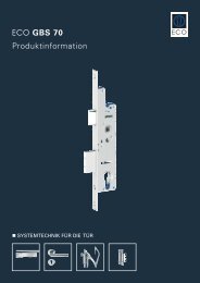
4 Construction and Function4.1 Construction1 2 34 5 6 7 1513 12 14 11 10 9 8 16Key to illustration:1 Mains connection terminals 9* Slide switch S1 (rotating direction)switch2 Fine-wire fuse 10* Multifunctional switch MF on STG3 Power supply NET 11 Closing spring4 Drive unit ATM 12 Vision panel adjust. spring tension5 Control unit STG 13* Adjusting screw for spring tension6 Connection terminals control unit 14 Connectors for arms (both sides)7 Motor print MOT 15 Standard switch BDI8 ATE drive unit terminals 16 Status signal and Reset button* Do not change any settings or adjustments! These operations are reservedexclusively for trained and authorized persons.4.2 ComponentsThe record <strong>DFA</strong> <strong>127</strong> swing door operator forms part of an electromechanical swingdoor system and comprises the following main components:Control unit STG:Driving unit ATE:Power supply NET:Control unit BDE:Intelligent, learning, microprocessor-controlled controlsystem.Low maintenance DC geared motor with electronic pathmeasurement and integral thermostatic protectiveswitch, gear box with adjustable spring tension.Compact 230 V power supply with integral input filterand over-voltage protection.As required with convenient, simple mechanical controlunit and / or a programmable electronic BDE-D.<strong>Operating</strong> <strong>instructions</strong> <strong>DFA</strong> <strong>127</strong> Full Power Rev. B 11/2006 Page 5 of 20