SOLAR ELECTRIC MODULE ES-124 & ES-62T Owners Manual and ...
SOLAR ELECTRIC MODULE ES-124 & ES-62T Owners Manual and ...
SOLAR ELECTRIC MODULE ES-124 & ES-62T Owners Manual and ...

Create successful ePaper yourself
Turn your PDF publications into a flip-book with our unique Google optimized e-Paper software.
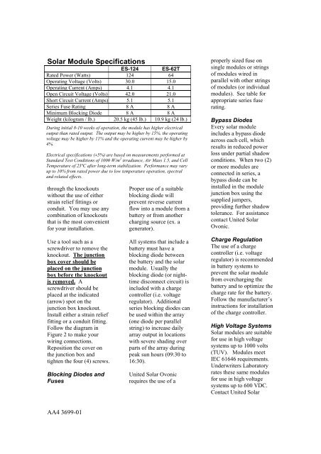
Solar Module Specifications<strong>ES</strong>-<strong>124</strong> <strong>ES</strong>-<strong>62T</strong>Rated Power (Watts) <strong>124</strong> 64Operating Voltage (Volts) 30.0 15.0Operating Current (Amps) 4.1 4.1Open Circuit Voltage (Volts) 42.0 21.0Short Circuit Current (Amps) 5.1 5.1Series Fuse Rating 8 A 8 AMinimum Blocking Diode 8 A 8 AWeight (kilogram / lb.) 20.5 kg (45 lb.) 10.9 kg (24 lb.)During initial 8-10 weeks of operation, the module has higher electricaloutput than rated output. The output may be higher by 15%, the operatingvoltage may be higher by 11% <strong>and</strong> the operating current may be higher by4%.Electrical specifications (±5%) are based on measurements performed atSt<strong>and</strong>ard Test Conditions of 1000 W/m 2 irradiance, Air Mass 1.5, <strong>and</strong> CellTemperature of 25ºC after long-term stabilization. Performance may varyup to 10% from rated power due to low temperature operation, spectral<strong>and</strong> related effects.through the knockoutswithout the use of eitherstrain relief fittings orconduit. You may use anycombination of knockoutsthat is the most convenientfor your installation.Proper use of a suitableblocking diode willprevent reverse currentflow into a module from abattery or from anothercharging source (ex. agenerator).properly sized fuse onsingle modules or stringsof modules wired inparallel with other stringsof modules (or individualmodules). See table forappropriate series fuserating.Bypass DiodesEvery solar moduleincludes a bypass diodeacross each cell, whichresults in reduced powerloss under partial shadowconditions. When two (2)or more modules areconnected in series, abypass diode can beinstalled in the modulejunction box using thesupplied jumpers,providing further shadowtolerance. For assistancecontact United SolarOvonic.Use a tool such as ascrewdriver to remove theknockout. The junctionbox cover should beplaced on the junctionbox before the knockoutis removed. Ascrewdriver should beplaced at the indicated(arrow) spot on thejunction box knockout.Install either a strain relieffitting or a conduit fitting.Follow the diagram inFigure 2 to make yourwiring connections.Reposition the cover onthe junction box <strong>and</strong>tighten the four (4) screws.Blocking Diodes <strong>and</strong>FusesAll systems that include abattery must have ablocking diode betweenthe battery <strong>and</strong> the solarmodule. Usually theblocking diode (or nighttimedisconnect circuit) isincluded with a chargecontroller (i.e. voltageregulator). Additionalseries blocking diodes canbe used within the array(one diode per parallelstring) to increase dailyarray output in locationswith severe shading overparts of the array duringpeak sun hours (09:30 to16:30).United Solar Ovonicrequires the use of aCharge RegulationThe use of a chargecontroller (i.e. voltageregulator) is recommendedin battery systems toprevent the solar modulefrom overcharging thebattery <strong>and</strong> to optimize thecharge rate for the battery.Follow the manufacturer’sinstructions for installationof the charge controller.High Voltage SystemsSolar modules are suitablefor use in high voltagesystems up to 1000 volts(TUV). Modules meetIEC 61646 requirements.Underwriters Laboratoryrates these same modulesfor use in high voltagesystems up to 600 VDC.Contact United SolarAA4 3699-01