AT500 OWNERS MANUAL - weller truck parts
AT500 OWNERS MANUAL - weller truck parts
AT500 OWNERS MANUAL - weller truck parts

Create successful ePaper yourself
Turn your PDF publications into a flip-book with our unique Google optimized e-Paper software.
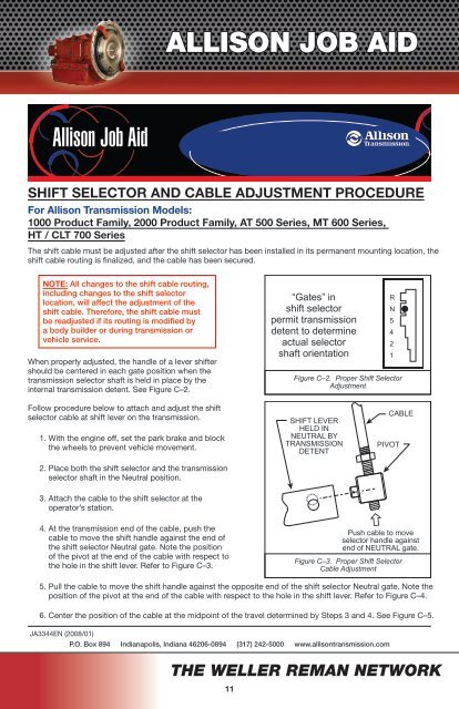
ALLISON JOB AIDAllison Job AidSHIFT SELECTOR AND CABLE ADJUSTMENT PROCEDUREFor Allison Transmission Models:1000 Product Family, 2000 Product Family, AT 500 Series, MT 600 Series,HT / CLT 700 SeriesThe shift cable must be adjusted after the shift selector has been installed in its permanent mounting location, theshift cable routing is finalized, and the cable has been secured.NOTE: All changes to the shift cable routing,including changes to the shift selectorlocation, will affect the adjustment of theshift cable. Therefore, the shift cable mustbe readjusted if its routing is modified bya body builder or during transmission orvehicle service.When properly adjusted, the handle of a lever shiftershould be centered in each gate position when thetransmission selector shaft is held in place by theinternal transmission detent. See Figure C–2.“Gates” inshift selectorpermit transmissiondetent to determineactual selectorshaft orientationRN5421Figure C–2. Proper Shift SelectorAdjustmentFollow procedure below to attach and adjust the shiftselector cable at shift lever on the transmission.1. With the engine off, set the park brake and blockthe wheels to prevent vehicle movement.2. Place both the shift selector and the transmissionselector shaft in the Neutral position.SHIFT LEVERHELD INNEUTRAL BYTRANSMISSIONDETENTPIVOTCABLE3. Attach the cable to the shift selector at theoperator’s station.4. At the transmission end of the cable, push thecable to move the shift handle against the end ofthe shift selector Neutral gate. Note the positionof the pivot at the end of the cable with respect tothe hole in the shift lever. Refer to Figure C–3.ñPush cable to moveselector handle againstend of NEUTRAL gate.Figure C–3. Proper Shift SelectorCable Adjustment5. Pull the cable to move the shift handle against the opposite end of the shift selector Neutral gate. Note theposition of the pivot at the end of the cable with respect to the hole in the shift lever. Refer to Figure C–4.6. Center the position of the cable at the midpoint of the travel determined by Steps 3 and 4. See Figure C–5.JA3344EN (2008/01)P.O. Box 894 Indianapolis, Indiana 46206-0894 (317) 242-5000 www.allisontransmission.comTHE WELLER REMAN NETWORK11