
You also want an ePaper? Increase the reach of your titles
YUMPU automatically turns print PDFs into web optimized ePapers that Google loves.
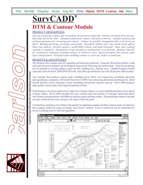
File Modify Display Draw Inq-Set Pnts 3Dpoly DTM Contour Site Miscengineeringsoftwareforanexpandinguniverse<strong>SurvCADD</strong>RDTM & Contour ModulePRODUCT DESCRIPTIONOne step contouring, volumes and site grading, the quickest in AutoCAD. Contour with labels all in one step.Hard and soft barrier lines. Automated depression contours with ticks at interval. Multiple inclusion andexclusion perimeters for contouring and volumes. Volumes by grid files, triangulation files or by layers (nofiles!). Building pad design, pit design, pond design. 3D polyline utilities (join, trim, extend, break, offset.)Slope zone analysis, elevation analysis, cut/fill depth contours and depth elevations. Slope ratio contoursconstant or cumulative. Interpolation of spot elevation at random points or at intervals. Quantity "take-off"for construction estimating, including analysis of earthwork zones, topsoil placement and removal, stonelayers and pavement. Powerful terrain modeling routines to create any surface or landscape.BENEFITS & ADVANTAGESSite designers have unique tools for regrading and balancing earthwork. Using the 3D polyline utilities, roadsand water diversion channels can be designed along terrain following any desired slope. Final terrain designscan be trimmed to existing surfaces--great for fills, building sites, parking areas. Landfill designers benefitespecially from the <strong>SurvCADD</strong> DTM 3D tools. Just offset up and bench over with 3D polyline offset routine!Any company that produces contour maps, including survey firms, civil engineering consultants and aerialphotogrammetry companies, will benefit from <strong>SurvCADD</strong>'s fast contouring and advanced editing tools, whichinclude polyline vertice reductions, bezier smoothing and polyline segment removal. <strong>SurvCADD</strong> produceshigh-quality contour maps with a logical minimum of steps.Pond designers can incise ponds of any shape into existing contours or create embankment dams across drainsof larger valleys. <strong>SurvCADD</strong> calculates the exact volumes and even includes a "re-design" option that allowsnear-instant experimentation with different outslope grades and dam widths. All pond design routines calculatenot only earthwork but water storage at all stages within the pond.Construction companies can estimate jobs quickly by digitizing existing and final contours at pre-set intervals,then compute earthwork using our unique "layer based" method. Zones of earthwork can be established forpaved or parking areas to fine-tune quantities.
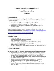
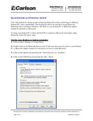
3Dpoly MenuWorking in 3D in AutoCAD by itself is simply unproductive. AutoCAD makes it difficult to offset, trim, extend, join or break 3Dpolylines. <strong>SurvCADD</strong> includes a host of 3Dpolyline utilites that duplicate AutoCAD's powerful 2D polyline utilites but work withboth 2D and 3D polylines. These design tools enable you to design, draw and edit entirely in 3D . <strong>SurvCADD</strong> liberates theAutoCAD designer allowing the user to work freely and effortlessly in 3D.Unique 3Dpolyline Utilities• Draw 3D Polyline - Draw 3D Polyline bypoint number or picking. Displays coordinateson each drawn vertex including elevation.Assign elevation feature.• Slope Line (3D polyline) - Draw 3D polylineby slope or ratio.• Draw 3D Polyline with Follow - Allows youto trace any existing 3D Polyline by selectingit's start location and end location. Multiple3D polylines can be traced with thiscommand.• 2D Polyline to 3D Polyline by Points orSurface Model - Convert 2D Polylinesthatintersect existing contours or TIN/Gridfiles to create ridgelines, top and bottom ofbanks . Great for converting streams andcurbs drawn as 2DPolylines in photogrammetrymaps to 3Dpolylines.• Break 3D Polyline by Surface - Uniquecommand extends or trims selected 2D and3D Polylines to tie into existing surfaces.Surface may be defined using screen contours,points or grid file. Great for splicing in3D Offset Polylines used to define benchesfor landfills and valley fills.• Tag or Untag Hard Barrier Lines - Usedto stop smoothing between two taggedpolylines when contouring manmade features(e.g. curbs, walls, steps, cliffs... ).Design roads and diversion ditches acrosscontour maps at any desired slope. Then usethe "3D Polyline Offset" <strong>SurvCADD</strong> commandto create parallel grade lines, leadingto final designs using the Pad Template routinein the Site menu.Offset 3D polylines to create road.Offset 3D polylines to create a landfill.• 3D Polyline by Slope on Surface -Draw a 3D polyline at a constant slope orratio along an existing contour, TIN or GRIDfile. Great for designing a haul road, channel,or ditch along an irregular surface at aconstant grade or slope ratio.• 3D Polyline Utilites - Offset, Trim, Extend,Join and Break allows you to edit/modify 3DPolylines as easily as 2D Polylines inAutoCAD. Any 3D structure (e.g. walls,steps, curbs,... .) can be drawn using 3Dpolylines snapping to their true elevationand offset or edited with the3D PolylineUtilites command. Complex sites reqiringgrading or regrading can be created quicklyin 3D and used for accurate contouring andvolumes.The "3D Polyline Offset" command offsetsboth horizontally and vertical an invaluabletool designing in 3D. The landfillwith benches containing sloping V-ditches designed using the "3D PolylineOffset, Trim and Extend" commands of<strong>SurvCADD</strong>..2D polylines at 0 elevation that intersect contours can be converted into 3D polylinesand used to design any desired regrade. The example above where a 0.25:1 highwallslope is designed to create a pit or building pad.2
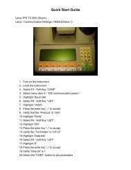
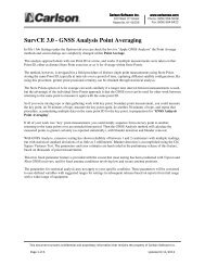
D.T.M. Menu• Interpolate Points/Entity or Points by SlopeRatio - Create COGO points interpolatedbetween points along polylines, lines/arcsand by slope ratio.• Make/Plot Grid Files & Grid Utilities -Create Digital Terrain Models (DTM) or Gridfiles from selected points, lines, 2D or 3DPolylines with elevations. Grid files can beplotted at any vertical exaggeration for 3Dviewing. Grid files can be edited, modifiedand combined using polyline perimeters.• Volumes by Grid Files - One Surface Volumescalculates the cut and fill volumesabove or below any datum elevation. TwoSurface Volumes calculates cut and fill volumesbetween two surfaces. Multiple inclusionand exclusion polyline perimeters canbe used. Cut and Fill differences can be plottedin specified rows or columns along thegrid files. Difference contours can be plottedwith labels. Cut and fill maps can becolor coded within difference contour intervals.Cut or fill volumes by elevation stagecan be output. Volumes for cut and fill canbe plotted cell-by cell using grid files or analyzedby multi-cell zones.• Volumes by Layers - One Step Volumes.Allows user to pick on screen or type layernames for existing and final grid files withininclusion and exclusion perimeters. Anynumber of layers can be thawed, only thoselayers specified will be used to create theexisting and final grid files . No files areneeded or created.Cut and fill volumes are displayed in an ASCIIeditor for editing and sent or stored to thedrawing, printer or file.• Volumes by Triangulation - Calculates volumesbetween two TIN files stored whencontouring.• Elevation Zone Analysis - Change colorson plotted grids files by elevation range.This command allows you to set and storecolor legends by elevation range for recall.Great for viewing grid files in 3D and displayingchanges in elevations with color legend.• Slope Zone Analysis - Calculates user definedslope zones and plots slope contours.Colors slope zone area and prints out slopearea report.• Slope Report - Reports average slope andminimum and maximum slopes within anyclosed polyline by grid file.• Build landfills, roads and diversion ditchessimply by offsetting 3D polylines. Thencheck volumes and redesign as needed. Ortake on challenging earthwork assignmentsas shown below. All design is in plan view,using 3D polylines as “wire frames”,overwhich contours or surface grids can bedraped for presentation.• The offset 3D polylines can be trimmed,one surface to another, by <strong>SurvCADD</strong>’sTRIM 3D POLYLINE BY SURFACE command.The 3D polyline connecting the intersectionrepresents where the two surfacesmake contact. The existing and final surfacesare selected and volumes calculatedfrom a polyline perimeter.Plot 3D grid files at any vertical exaggeration.Regrading — No other package let’s you design grading quicker.3Volume calculations between existing & finished grade contours.
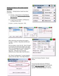
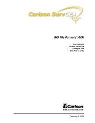
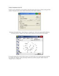
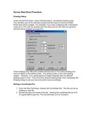
Contour Menu• Triangulate & Contour - One step contouring.Preset index and intermediate contourintervals, layers and contour labelingoptions. Select points, lines, 2D and 3Dpolylines with elevations, pick inclusion andexclusion perimeters, then <strong>SurvCADD</strong> contoursand labels. Smoothing and automaticvertice reduction are preset to create accuratesmooth contours with minimal vertices.The Triangular Irregular Network or TIN canbe plotted during the contour process as 3Dlines or 3D Faces and stored to a file.<strong>SurvCADD</strong> is the only civil software thattriangulates and contours without the needto store or display the TIN. If you want onlythe contours, use Triangulate & Contour. Noother AutoCAD civil based package contoursfaster or with fewer steps.• Global Elevation Label and Local ElevationLabel commands - Contours can be labeledafter contouring using these commands.Labels can be boxed.• Highlight Depression Contours - Highlights,Layerizes and places depression tickmarks on all contours in depression drainageareas.• Trim Contour-Plines by pline - This commandtrims all polylines inside or outside apolyline.• Change Contour-Plines Width - All indexcontours or any polylines can be globallyset to a certain width.• Assign Contour Elevations - External contourmaps drawn as polylines at zero elevationcan have their elevations quickly setwith this command. New elevation, intervaland layer can be set or changed within thiscommand without exiting.• Tablet Calibrate & Digitize contours -Configures digitizer to be used to digitizecontours with known elevation. Auto TabletOn, toggles the digitizer between tabletcalibration and selecting from digitizer tabletmenu for AutoCAD/<strong>SurvCADD</strong> commands."Just Window thePoints and Break Lines,Creating High QualityContour Maps!"Triangulate & Contour draws Index/Intermediate contours at any interval withlabels, within any inclusion and exclusionpolyines.• Edit TIN files on screen.• Contours may be drawn from TIN or gridfiles, stored or displayed .• Digitized, blocky contours can be smoothedby the accurate "Bezier" algorithm. Largecontour files, particularly files imported fromother software can be reduced to manageablesize by using Reduce Contour Vertices.File sizes after Reduce Contour Vertices, veryoften achieve 30% to 50% size savings withoutreducing accuracy or smoothing.• List Elevation - Displays elevation of any2D or 3D contour selected.<strong>SurvCADD</strong>'s contouring does not require storing a TIN file, but if you want to draw theTIN you may, as 3Dlines or 3Dfaces. As an option TIN files can be stored to a ASCIIfile for Volumes and Hydrology.<strong>SurvCADD</strong>'s points are plotted at their true 3D or Z elevation. <strong>SurvCADD</strong> can contourfrom screen entities in plan or any 3Dview. 3D lines, 2D or 3DPolylines with elevationsact as barrier lines.4
Site Menu<strong>SurvCADD</strong>'s Site Design has been a secret weapon for many civil engineering, surveying, construction and mining companies since1992. We were the first and remain the only company that completes site design in one step without the necessity of storing preliminaryFLT or Grid files. This unique ability allows our users to tie in any site, road, bench pond and valley dam to an existing surface, usingonly screen entities (e.g. photogrammetry contour map, digitized contours, contours from survey data...). By selecting only screenentities in the disturbed area both speed and accuracy are maximized and the need for elaborate project file management is minimizedor nonexistent. <strong>SurvCADD</strong> can also use stored surface FLT and Grid files for site design. <strong>SurvCADD</strong>'s newest site development featurein Design Pad Template applies a true simple or complex template to a 3D polyline representing the horizontal and vertical alignment.This feature draws the template in 3D with finished grade contours tied to existing contours, volume report is generated for cut andfill. Now roads or any template design can be drawn in 3D directly in plan view quickly and accurately, without creating cross-sectionsand running through conventional template design. Another AutoCAD first from <strong>Carlson</strong> <strong>Software</strong>!!!• Design Pad Template - Ties any picked 2Dor 3D open or closed polyline into an existingsurface defined as either screen entities(contours, spot elevations...), FLT or Grid file.Great for tieing in complex commercial andresidential sites or simple parking lots, roads,channels and ditches to an existing surface.The final design is drawn as a complete, 3D"wire frame" figure. A closed 3D polyline isdrawn around the perimeter, defining the disturbedarea. Finished grade contours aredrawn inside the disturbed area polyline.Existing contours inside the disturbed areapolyline can be trimmed out, with finishedgrade contours tied into existing contours.A volume report is generated for cut and fillin cubic yards and feet, this can be modified,screen plotted, sent to the printer or storedto a file. <strong>SurvCADD</strong>'s latest feature includesthe ability to apply a complex road templatecreated in the Section & Profile module toany 3D polyline that represents the horizontaland vertical road alignment. Using theDesign Pad Template command any template(even including, inside & outside curbs,median, sidewalks, ditches, berms and transitionaloutslope treatments...), can be tiedto an existing surface, drawing the outslopes,disturbed area polyline, all in 3D with proposedcontours and cut/fill volume report.In seconds.• Design Bench Pond - This command worksonly with a closed 2D polyline that definesthe top of the pond. The pond can be anysimple or complex closed polyline with bothline and arc segments. Slopes in percent orratio are drawn both outward and inwardfrom the picked pond perimeter. The pond"berm" can have any width. Outslopes aredrawn as 3D polylines, and a 3D polylineperimeter connecting all outslopes definesthe disturbed area. Finished grade contoursare drawn inside the disturbed area polyline.Existing contours inside the disturbed areapolyline can be trimmed out and finishedgrade contours tied into existing contours.The interior downward slope from the of thetop of the inside berm can tie either to theexisting surface or to a fixed elevation forbottom of pond. The interior down slope isdefined separate from the outslope treatmentin percent or ratio. Volumes for cut and filland pond stage storage capacity (acre feetand cubic feet/yards) are displayed withineven elevation intervals. The volume andpond stage storage report can be modified,screen plotted, sent to the printer or storedto a file. Pond capacity files can be storedfor stage storage graphing and plotting.• Valley Pond Design - This command workswith a linear 2D polyline that defines the topof a dam. Dam width and downslope gradesin percent or ratio are entered. Outslopesare drawn as 3D polylines with a 3D polylineperimeter drawn connecting all outslopes definingthe disturbed area. Contouring andvolume reporting are identical to the benchpond routine. The high water mark elevationinside the dam is drawn as a closed 2Dpolyline defining the perimeter of the storagearea.5• Design Pad from Boundary - Creates a padperimeter from the disturbed limit boundaryand design slopes.• Spot Elevations & Entities to Points - Createand plot random or gridded points fromscreen entities, FLT or Grid file. Great forcreating points for stakeout. For randompoints simply move the cursor along thesurface and the current elevation displayson the sidebar as fast as you move the cursor.Great for checking grades. Pick a locationanywhere on your map and a point iscreated and drawn with the surface elevation.To create gridded points for stakeoutpick a polyline or an alignment file (*.CL),specify offset distance left and right, intervaldistance to create points on left and rightsides and station interval. Points with elevationsand descriptions defining stationand offset left or right are created and plotted.Points uploaded to data collector canbe used for stakeout with point descriptions,helpful for verifying proper location.• Draw 3DPoly Perimeter & Base Barrier3D polylines - Draw base surface perimeterand base barrier lines in preset layers for onestep stockpile, pond and surface pit volumesbelow..• Calculate Stockpile, Pond and Surface PitVolumes - Creates volumes by simplywindowing a closed 3D polyline in the perimeterlayer, that envelops both base andfinal entities for the stockpile, pond or surfacepit. The volume report can be modified,screen plotted, sent to the printer or storedto a file. Stockpiles display only fill volumesand ponds and surface pits only cut volumes.No TIN or grid files are stored. Volumesfor each stockpile, pond and surfacepit are created in seconds and all you didwas window the entities.• Define Earthwork Zones & CalculateEarthwork - When estimating quantitiesusing existing and final contours, it is oftennecessary to deduct for stone and asphalt
in areas of parking lots, roads and buildingsso that a true volume to subgrade is calculated.This is achieved by associating materialsand depths with polylines definingthese "earthwork zones". A parking areamight have 4" of asphalt and 8" of stone,indicating that true subgrade is 1' below thesurface. The program also considers shrinkageand swell as well as topsoil removal andreplacement. With the Earthwork Zones defined,one simple window of the entities computesall quantities.• Name Zone Polylines - Assigns names tozone polylines so that Calculate Earthworkcan report volumes for each p[olyline byname."<strong>SurvCADD</strong> the quickest mostaccurate volume results insideAutoCAD meeting all yourestimating, earthwork reportingand project management needs."6