Data Entry.pdf - Carlson Software
Data Entry.pdf - Carlson Software
Data Entry.pdf - Carlson Software

You also want an ePaper? Increase the reach of your titles
YUMPU automatically turns print PDFs into web optimized ePapers that Google loves.
Survey <strong>Data</strong> <strong>Entry</strong> Procedure<br />
Drawing Setup<br />
Under Inq-Set Pull-Down, select 'Drawing Setup', set desired drawing scale.<br />
This will take care of the standard symbol and text sizes for the SurvCADD<br />
Points that will be created. For example, if you have a drawing with a Horizontal<br />
scale set to 100, with the Symbol and Text sizes set to 0.08, then the symbols<br />
and text will be inserted at a size of 8.<br />
These settings only affect the symbol and text sizes in the active drawing and<br />
have no affect on the plotting scale. The plotting scale is set in the plotting<br />
routine. However, it is a good practice to begin drawings with the desired<br />
plotting scale in mind. If you know the desired plotting scale, then manipulate the<br />
Drawing Setup to set your text and symbol size accordingly.<br />
Setting a Coordinate File<br />
1. From the Pnts Pull-Down, choose Set Coordinate File. This file can be an<br />
existing or new file.<br />
2. Specify the type and name of the file. Naming the coordinate file up front<br />
is a good habit to get into. This will eliminate a lot of confusion.
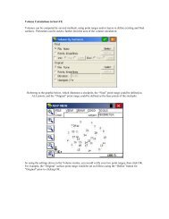
Traverse <strong>Entry</strong> Settings<br />
There are a number of settings that can be manipulated at this point by the<br />
user. These settings are user preferences. If you would like to have lines drawn<br />
between each traverse point, then from the Cogo Pull-Down select the Line<br />
On/Off option. This will place a check mark beside this option to let the user<br />
know that this has been selected and is in effect. Again, checking this option on<br />
will instruct the program to draw lines between the traverse stations.<br />
If you prefer or would also like to produce a raw file, RW5 extension, simply from<br />
the Cogo Pull-Down select the Raw File On/Off option. This will also place a<br />
check mark beside this option to let the user know that this option has been<br />
selected and is now in effect. The Raw <strong>Data</strong> File, RW5 extension is a very useful<br />
file for the surveyor. This file gives the surveyor the ability to review his raw<br />
data, process his raw data, make changes to the raw data and then reprocess<br />
the data. This file also allows for traverse adjustment using different methods.<br />
Also the options for the various point data should be set now.<br />
Under the Pnts Pull-Down, Point Default option select the desired options.<br />
If you would like to plot descriptions when the points are drawn on the screen<br />
or prompted for a point description when creating points, place a check in<br />
Descriptions box.<br />
To include elevations when drawing points on screen or to be prompted for<br />
elevations when creating points place a check in the Elevations box.<br />
The Locate on Real Z Axis allows the user to located points on the true<br />
elevation, or when checked off to locate points on zero elevation.<br />
The Instrument & Rod Height option, when checked on will prompt for<br />
instrument and rod height during traverse entry on screen.<br />
The Symbol Number option, when toggled on, will allow for a prompt for a<br />
symbol number as each point is drawn. Otherwise the Symbol Number set in<br />
the Point Settings dialog box will automatically be used.
Locating Starting Points<br />
From the Pnts Pull-Down, select Locate Points. Now you are ready to locate the<br />
first occupied point and backsight point. These points can be located on the<br />
screen by picking points or can be located by known or assumed coordinates. If<br />
a picked location on the screen is desired, just simply pick the points on the<br />
screen. Be sure to pick the location of the backsight first and then the first set-up<br />
point. This way the program will be orientated. If known or assumed coordinates<br />
are used, select "E" for enter coordinates, and simply enter the coordinate<br />
values. The program prompts for northing first and then easting. These prompts<br />
will be seen if you keep your eyes on the command line prompt.<br />
Traversing<br />
From the Cogo Pull-Down, select Traverse. Assuming that the backsight point<br />
was located first and then the first occupied point, you are now ready to begin
traverse entry. If the backsight was located last in the above described steps,<br />
then the Inverse command should be executed to orientate the program. To do<br />
this select from the Cogo Pull-Down, - Inverse. Then inverse from the occupied<br />
point to the backsight point and then back to the occupied point. By selecting<br />
point number 2 to 1. Although this may seem like a unnecessary step, it is<br />
necessary because the program recognizes the last located point as the<br />
occupied point. Even if you are traversing using azimuths or bearings, you would<br />
have to inverse to the correct occupied point in order to proceed with the<br />
traverse. If the backsight was located first and the occupied point last then the<br />
inverse described above is unnecessary. Now continuing with our first<br />
assumption lets begin traverse entry. At this point it is important to point out a<br />
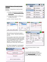
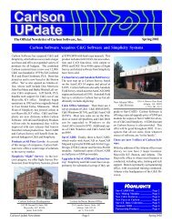
recommendation that is very useful. We recommend that the AutoCAD Screen<br />
Menu be present in the drawing window. This allows for the user to see the<br />
codes for the various traverse entry options at all times. These codes define<br />
whether the data is entered as angle right, angle left, bearing, azimuth, deflection<br />
right or left etc. Having this menu turned on relieves the user from having to<br />
memorize the codes to be used. To turn this menu on, from the File Pull-Down,<br />
select Preferences, then click on the Display tab, and then place a check in the<br />
checkbox. (See below)<br />
At this point the traverse entry begins. If the steps above have been followed,<br />
the instrument is occupying the first traverse point and the program has been<br />
orientated to the backsight. Simply enter the first shot by selecting the<br />
appropriate code from the side menu, the angle, distance and vertical or zenith<br />
angle of the shot. If the Instrument Rod Height option was turned on, you will be<br />
prompted for the instrument and rod heights. When the data entry for the first<br />
shot is entered you will be shown the calculated elevation of the point base upon<br />
the data input. You have the ability to enter the elevation of each shot if you so<br />
desire.<br />
Also if automatic numbering is on, then each shot will be numbered in sequential<br />
order. If this option has been turned off then you will be prompted for the point<br />
number.<br />
In addition you will be prompted for the description for the shot. Continue data<br />
entry until complete.<br />
Overview of Above<br />
The steps outlined above will assist the user with data entry of a survey. Every<br />
surveyor will have his or her own preference for most of the options described
above, and this narrative is designed to only aid in understanding the options<br />
provided to the user by the software. The specific requirements of the program,<br />
for example toggling on the edit process raw data file, described above are<br />
described in order to illustrate how and why the user may want to use these<br />
options.<br />
Edit Process Raw<br />
This section is devoted to assist or provide instruction on how to edit, process or<br />
adjust the survey data entered above. Please refer to the manual for specific<br />
codes for the data.<br />
If the Raw File On/Off under the Cogo Pull-Down was toggled on before the<br />
survey data entry then a raw file was created during the data entry. To view, edit<br />
and process this raw file select from the Cogo Pull-Down, Edit Process Raw <strong>Data</strong><br />
File. You will be prompted for an existing or new file. If an existing file is desired,<br />
as would be the case if the steps above have been followed, you would simply<br />
select the existing button and the desired file. However before we get into the<br />
processing procedures lets look at the options if we select the New option. If<br />
new was our selection, then we would be prompted for the name of the raw file to<br />
be created. Next you are prompted for the name of the coordinate file to be used<br />
with the raw file, existing or new. You can use an existing coordinate file if<br />
desired. However, most often you will want to specify a new coordinate file.<br />
After the file is named, an empty raw file sheet will appear on the screen.<br />
At this point data entry in a spread sheet format is available. The far left column<br />
on the spreadsheet is for the type of data. Examples of these "types" are PT for<br />
points, BK for backsight, TR for traverse and SS for sideshot. Again please refer<br />
to the manual for the specific types of data codes.<br />
To get started let's input a point.<br />
1. From the type column pick on the down arrow and select the PT code.<br />
2. Enter the point number, northing, easting, elevation and description. Note<br />
that this is the format for the spreadsheet headings for the point code.<br />
3. Now from the ADD Pull-Down located at the top of the spread sheet select<br />
Backsight. Note how the heading in the spreadsheet changes to reflect<br />
OcPt, BsPt, Azi and Set Azi.<br />
4. Fill in the blanks. If you are using a random point for the backsight and<br />
setting the instrument to "0", fill in the set Azimuth column with a 0. You<br />
need only to fill in the Azi or the Set Azi column with 0 not both. Also if<br />
you had a specific azimuth from the occupied point to the backsight you<br />
could enter it instead of 0. Lastly, if you had a known point to be used for<br />
a backsight, with a known azimuth from the occupied point, it can be<br />
specified here. It should be noted that if you are going to specify a point<br />
for a backsight, for example occupied point 1 backsight point 2, point 2<br />
would have to be defined with coordinates as a point record.
Now lets add a traverse entry. Select from the ADD Pull-Down, Traverse. Note<br />
that now the code in the type column is now changed to TR and the spread sheet<br />
headings have changed to Code, HorzAngle, SlopeDist, ZenithAng and Desc.<br />
The later four headings are self explanatory, however the Code column is where<br />
the actual type of the shot is recorded. For example for an Azimuth entry the<br />
code is AZ, northeast, southeast, southwest and northwest bearing entries are<br />
coded by the letters NE, SE, SW and NW. Angle right, angle left, deflection right<br />
and deflection left entries are coded by the letters AR, AL, DR and DL.<br />
To enter a side shot from an occupied point, the only change that would need to<br />
be made is that of the type. In the type column, the code would be SS for<br />
sideshot. Note that if a instrument height and rod height record is to be added,<br />
you would move the cursor to the cell that the record needs to be placed in front<br />
of. For example to include an instrument height record for station 4 and a rod<br />
height record for station 5 then the cursor would be placed in the cell containing<br />
the occupied point 4 entry. Then the Add Pull-Down would be selected and the<br />
Instrument Height option selected. This will place the HI record above traverse<br />
entry from station 4 to station 5 as it should be. <strong>Data</strong> entry would continue until all<br />
data is entered into the spreadsheet. If survey data has been downloaded from a<br />
data collector, then the edit process raw file spread sheet will be filled out<br />
automatically.<br />
Raw File Preparation From CRD File<br />
Another useful advantage of the Edit Process Raw File routine, is the ability to<br />
use a CRD file or plotted points on the screen to fill in the raw file spread sheet.<br />
Some preparatory work is required for this to work.<br />
First if points are located on the screen, they need to also be stored in a CRD<br />
file. Basically the user needs to know what type and how many traverse shots<br />
are represented. Only the coordinates of the beginning traverse point needs to<br />
be input into the spread sheet if the surveyor is going to set up on the initial point<br />
and backsight any object, such as a tack in a tree or power pole, with zero. If the<br />
surveyor is set up on one point and taking a backsight on another point with<br />
known coordinates, then both the initial and backsight points need to be defined<br />
by coordinates. This is simple to do. The user need not type the coordinates of<br />
these points into the spreadsheet. Simply from the ADD Pull-Down menu select<br />
Point. A row will now be created with the type column defined as PT. If only one<br />
known coordinate is needed, you are ready to proceed. However, if the<br />
backsight point has known coordinate values then another point entry row needs<br />
to be added.<br />
From the Add Pull-Down again select Points. Another row with the Pt type is<br />
inserted. At this point simply go to the first PT record that was added and type in<br />
the point number in the PNTNO column. If a known point is being used for the<br />
backsight then enter the number of this point in the second Pt row.<br />
From the Options Pull-Down select Update Raw From Points. Either one or both<br />
of the added PT record rows will now be filled in with the coordinates of the<br />
specified points. Now select the Add Pull-Down again and add a Backsight
ecord. Specify the occupied point and the backsight point. Next select the Add<br />
Pull-Down and select Traverse. Fill in the occupied point number and the<br />
foresight point number. If the Code column is left blank then when the routine<br />
will use the appropriate bearing codes in this column. If a particular code is<br />
desired then it should be selected. All that is needed is one column of data to be<br />
filled out.<br />
Place the cursor in the Horizontal Angle cell and simply select the Add Pull-Down<br />
and Traverse and add traverse entry rows. The point numbers will automatically<br />
be input in sequential order while the code column will be filled in with the desired<br />
code if input in the first line of traverse entry. When the appropriate number of<br />
lines has been added to the spread sheet, then again from the Options Pull-<br />
Down select Update Raw From Points and the spread sheet will be filled in. This<br />
option is useful when survey drawings are received from other surveyors. A<br />
coordinate file can be created from the points on the screen by selecting from the<br />
PNTS Pull-Down, Coordinate File Utilities, Update From Drawing, or from the<br />
Cogo Pull-Down, Convert Entities to Points - Entities to SurvCADD Points. If a<br />
coordinate file has not already been specified then a prompt for the name of the<br />
coordinate files will appear. From this coordinate file a raw file can be created<br />
that can be edited and processed an endless number of times.<br />
Process No Adjust<br />
This routine processes the raw file and stores the calculated coordinates to the<br />
CRD file. First a dialog prompts for some user preferences as shown below.<br />
For any direct and reverse raw data, there is the option to process the directreverse<br />
shots and use only the foresight direct shot. There is an option whether<br />
to include the sideshot data in the process results report. This option may be
turned off, in the case of a large quantity of sideshots, so that only the traverse<br />
shots are displayed in the process results dialog box. The point protect option<br />
will check the coordinate file for existing point data before processing. If the<br />
foresight point number for any traverse or sideshot record already is a stored<br />
coordinate in the CRD file, then the program shows a list of conflicting point<br />
numbers. You can either continue processing and overwrite the CRD file<br />
coordinates with the calculated raw file coordinates or cancel the processing to<br />
go back to the editor to change foresight numbers.<br />
This routine assumes that the traverse begins and ends on the same point. A<br />
closure cannot be calculated for an open traverse in this routine in the present<br />
version of SurvCADD 98. An option for this will be added to the release due out<br />
sometime this year. However closure for open traverses can be calculated upon<br />
adjustment of the traverse.<br />
Processing with Different Adjustment Methods<br />
The key to any adjustment is the set up of the raw file. For a closed traverse,<br />
ideally, the user would tag a closing shot, CL in the Type Column, and an angle<br />
balance shot, AB in the Type Column. These shots do not have to be defined in<br />
the raw file, however, if they are not specified in the file then the user will be<br />
prompted during the adjustment routine for these respective shots. It makes it a<br />
lot easier and less confusing if the shots are identified in the raw file spread<br />
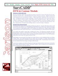
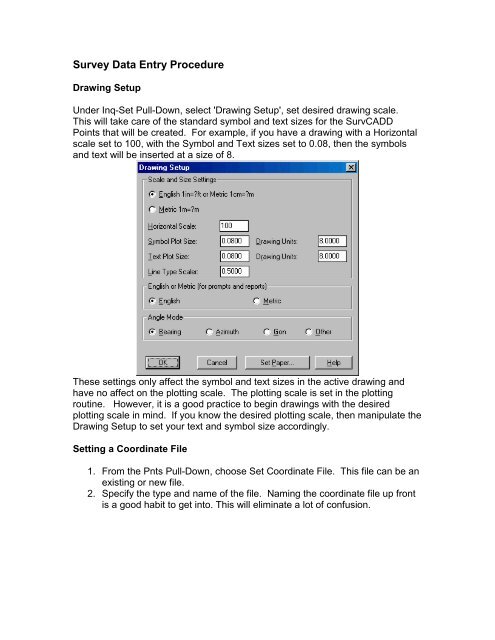
sheet. The following illustration shows a closed traverse raw file properly set up<br />
for the survey adjustment.
The above example shows a raw file that represents a closed traverse, with<br />
elevations and instrument heights, that begins on station 1, backsights known<br />
point 20, and traverses through sequential shots with shot 8 being the ending<br />
shot and the same as station 1. Please note that if a known Azimuth or Bearing<br />
from point 1 to backsight point 20 was desired it could have been input into the<br />
set azimuth column. This file was created by toggling on the Raw File ON/OFF<br />
option under the Cogo Pull-Down before actual data entry. <strong>Data</strong> entry was<br />
performed on screen. Note that shot 7 to 8 has been tagged as a CL record,<br />
closing shot and an additional shot from 8 to 9 has been tagged as an AB record,
angle balance shot. Shot 8 to 9 is required for the angle balance. This shot<br />
allows the user to use the angle tie shot from the closing point to the original<br />
backsight point for the angle balance.<br />
If another traverse line is desired for the angle balance, then the desired traverse<br />
leg should be tagged as the angle balance shot, AB record. In most cases<br />
however, the angle tie shot from the closing point to the original backsight will be<br />
the angle balance shot. In the example above the azimuth from point 8, which is<br />
the closing shot, to point 20, which is the initial backsight point, is 0.0007. The<br />
original backsight was 0.0000. So the angular error for this traverse is 7<br />
seconds. Now lets look at the different methods of traverse adjustment.<br />
From the Process Pull-Down in raw file editor, select Angle Balance. In every<br />
adjustment option, including process no adjust, the user has the option of<br />
reporting sideshots in the process results dialog box. This is user preference and<br />
if you don't want to report the sideshots, simply turn off this option. The angle<br />
balance adjustment balances the angles only. The process results shows the<br />
closure before adjustment and also the closure after angle balance. The process<br />
result dialog box is set up so the user can scroll up or down to see all of the<br />
information contained in the process results. The closure after angle balance<br />
can be and often is less than the unadjusted closure.<br />
Please note that the angle balance routine does not have to be run first in order<br />
to use adjusted angles in the other adjustment routines. In each of the<br />
adjustment routines, the option to apply angle balance is provided. After<br />
selecting Angle Balance from the Process Pull-Down, the same dialog box<br />
shown above under No Adjust will appear.<br />
These options are user preference and have been described earlier in this<br />
document. When the options are selected as desired click the OK button. It is<br />
important to remember that in this example the angle balance shot has been<br />
specified in the type column. If this shot had not been specified, the user would<br />
be prompted for the angle balance shot prior to seeing the Reference Closing<br />
Angle dialog box. The Reference Closing Angle dialog box shown below, allows<br />
the user to specify the correct closing angle for the traverse.<br />
It also shows, based upon the data input and setup, measured closing Bearing,<br />
Azimuth and the angular error. From the example the measured closing bearing<br />
in N 0.0007 E and the Azimuth is 0.0007 for an angular error of 0.0007, or 7<br />
seconds. The correct azimuth for angle tie, we know is the line between the<br />
beginning point and the initial backsight, which in this case was 0.0000. So to
specify the reference closing angle, we can either type 0.0000 in the reference<br />
closing angle window or we and specify, in the appropriate windows, from point 1<br />
to point 20. If we do the later, the reference closing angle window will be<br />
automatically filled in with the initial backsight data. Upon selecting the OK button<br />
the process will appear in the Process Results dialog box.<br />
The process results will first show the unadjusted traverse legs and the<br />
unadjusted closure for the traverse.<br />
(A single screen shot of the report viewer would not show you the entire closure<br />
report, so only the report text is shown below)<br />
Process Results 07/29/2001 17:30<br />
Raw file> c:/scadces/data/drawing1.rw5<br />
CRD file> c:/scadces/data/drawing1.crd<br />
Scale Factor: 1.00000000<br />
Correct for Earth Curvature: OFF<br />
Starting Point 1: N 5000.000 E 5000.000 Z 1000.000<br />
BackSight Azimuth: 00°00'00"<br />
Point Horizontal Zenith Slope Inst Rod Northing Easting Elev<br />
No. Angle Angle Dist HT HT<br />
Description<br />
2 AZ47.2559 89.1554 250.266 5.000 4.600 5169.279 5184.303 1003.610<br />
IPF<br />
3 AZ126.2548 90.0000 150.620 5.100 5.000 5079.835 5305.489 1003.710<br />
IPF<br />
4 AZ140.1010 89.5214 225.512 5.250 4.980 4906.655 5449.933 1004.490<br />
IPF<br />
5 AZ181.2552 87.5245 314.256 5.100 5.050 4592.712 5442.090 1016.170<br />
IPS<br />
6 AZ247.5810 91.2529 305.238 5.050 4.890 4478.252 5159.227 1008.740<br />
SCRIBED X<br />
7 AZ295.3213 91.2516 250.002 5.000 4.890 4585.993 4933.718 1002.650<br />
FP<br />
8 AZ9.0525 90.2212 419.536 5.000 4.890 5000.252 4999.999 1000.051<br />
END PT<br />
9 AZ0.0007 90.0000 1.000 5.000 4.890 5001.252 4999.999 1000.161<br />
ORG BK<br />
Closure Results (Before Angle Balance)<br />
Starting Point 1: N 5000.000 E 5000.000 Z 1000.000<br />
Ending Point 8: N 5000.252 E 4999.999 Z 1000.051<br />
Azimuth Error : 359°45'24"
North Error : 0.25163<br />
East Error : -0.00107<br />
Vertical Error: 0.05084<br />
Hz Dist Error : 0.25163<br />
Sl Dist Error : 0.25672<br />
Traverse Lines> 7<br />
SideShots> 0<br />
Horiz Dist Traversed: 1915.014<br />
Slope Dist Traversed: 1915.430<br />
Closure Precision: 1 in 7610<br />
Angle Balance<br />
Angular Error: 0.000700000 for 7 traverse sides<br />
Adjusting Each Angle: 0.000100000<br />
Point Horizontal Zenith Slope Inst Rod Northing Easting Elev<br />
No. Angle Angle Dist HT HT<br />
Description<br />
2 AZ47.2559 89.1554 250.266 5.000 4.600 5169.279 5184.303 1003.610<br />
IPF<br />
3 AZ126.2547 90.0000 150.620 5.100 5.000 5079.835 5305.489 1003.710<br />
IPF<br />
4 AZ140.1008 89.5214 225.512 5.250 4.980 4906.657 5449.935 1004.490<br />
IPF<br />
5 AZ181.2549 87.5245 314.256 5.100 5.050 4592.714 5442.097 1016.170<br />
IPS<br />
6 AZ247.5806 91.2529 305.238 5.050 4.890 4478.249 5159.236 1008.740<br />
SCRIBED X<br />
7 AZ295.3208 91.2516 250.002 5.000 4.890 4585.984 4933.724 1002.650<br />
FP<br />
8 AZ9.0519 90.2212 419.536 5.000 4.890 5000.244 4999.993 1000.051<br />
END PT<br />
9 AZ0.0000 90.0000 1.000 5.000 4.890 5001.244 4999.993 1000.161<br />
ORG BK<br />
Closure Results (After Angle Balance)<br />
Traverse Lines> 7<br />
SideShots> 0<br />
Starting Coordinates: N 5000.000 E 5000.000 Z 1000.000<br />
Ending Coordinates: N 5000.244 E 4999.993 Z 1000.051
Azimuth Error : 358°23'57"<br />
North Error : 0.24448<br />
East Error : -0.00683<br />
Vertical Error: 0.05084<br />
Hz Dist Error : 0.24458<br />
Sl Dist Error : 0.24981<br />
Total Hz Dist Traversed: 1915.01356<br />
Total Sl Dist Traversed: 1915.43000<br />
Closure Precision: 1 in 7830<br />
Compass, Crandall and Transit Adjustment Methods<br />
In all of these adjustment methods, if the raw file has been set up like the one in<br />
our example, the same dialog boxes will appear. To avoid duplication only the<br />
Compass Method will be shown here. From the Process Pull-Down select<br />
Compass. As a reminder, if the closing traverse leg, or closing shot, and the<br />
angle balance shot have not been identified in the raw file, then the user will be<br />
prompted for this information. However, if the raw file is set up as in our<br />
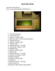
example, then the following Closure Options dialog box will appear.<br />
In this box various user defined preferences can be set. The most important part<br />
of this box is the Reference Closing Point record. This field should be filled in<br />
with the point number that the survey closes to. In our example, which is a
closed traverse, our closing point is point 1. If we type the point number in the<br />
point number field and press enter, then the coordinates for the point will appear<br />
in their respective fields.<br />
When the dialog box has been filled in with the desired preferences and the<br />
closing point record click on the OK button. Now the Reference Closing Angle<br />
dialog box will appear. Again as in the Angle Balance routine, specify either the<br />
closing angle by survey data from shot to shot or by simply typing in the<br />
reference closing angle in the reference closing field. After the required<br />
information has been entered into the dialog box, click the OK button and the<br />
Process Results dialog box will appear.<br />
As with the angle balance process results, the results dialog box will show the<br />
unadjusted traverse legs and the closure results before adjustment first. Then<br />
the angular error and angular adjustments along with the closure report after the<br />
angle balance will be shown.<br />
(A single screen shot of the report viewer would not show you the entire closure<br />
report, so only the report text is shown below)<br />
Process Results 07/29/2001 17:37<br />
Raw file> c:/scadces/data/drawing1.rw5<br />
CRD file> c:/scadces/data/drawing1.crd<br />
Scale Factor: 1.00000000<br />
Correct for Earth Curvature: OFF<br />
Starting Point 1: N 5000.000 E 5000.000 Z 1000.000<br />
BackSight Azimuth: 00°00'00"<br />
Point Horizontal Zenith Slope Inst Rod Northing Easting Elev<br />
No. Angle Angle Dist HT HT<br />
Description<br />
2 AZ47.2559 89.1554 250.266 5.000 4.600 5169.279 5184.303 1003.610<br />
IPF<br />
3 AZ126.2548 90.0000 150.620 5.100 5.000 5079.835 5305.489 1003.710<br />
IPF<br />
4 AZ140.1010 89.5214 225.512 5.250 4.980 4906.655 5449.933 1004.490<br />
IPF<br />
5 AZ181.2552 87.5245 314.256 5.100 5.050 4592.712 5442.090 1016.170<br />
IPS<br />
6 AZ247.5810 91.2529 305.238 5.050 4.890 4478.252 5159.227 1008.740<br />
SCRIBED X<br />
7 AZ295.3213 91.2516 250.002 5.000 4.890 4585.993 4933.718 1002.650<br />
FP<br />
8 AZ9.0525 90.2212 419.536 5.000 4.890 5000.252 4999.999 1000.051<br />
END PT
9 AZ0.0007 90.0000 1.000 5.000 4.890 5001.252 4999.999 1000.161<br />
ORG BK<br />
Closure Results (Before Angle Balance)<br />
Starting Point 1: N 5000.000 E 5000.000 Z 1000.000<br />
Closing Reference Point 1: N 5000.000 E 5000.000 Z 1000.000<br />
Ending Point 8: N 5000.252 E 4999.999 Z 1000.051<br />
Azimuth Error : 359°45'24"<br />
North Error : 0.25163<br />
East Error : -0.00107<br />
Vertical Error: 0.05084<br />
Hz Dist Error : 0.25163<br />
Sl Dist Error : 0.25672<br />
Traverse Lines> 7<br />
SideShots> 0<br />
Horiz Dist Traversed: 1915.014<br />
Slope Dist Traversed: 1915.430<br />
Closure Precision: 1 in 7610<br />
Angle Balance<br />
Angular Error: 0.000700000 for 7 traverse sides<br />
Adjusting Each Angle: 0.000100000<br />
Point Horizontal Zenith Slope Inst Rod Northing Easting Elev<br />
No. Angle Angle Dist HT HT<br />
Description<br />
2 AZ47.2559 89.1554 250.266 5.000 4.600 5169.279 5184.303 1003.610<br />
IPF<br />
3 AZ126.2547 90.0000 150.620 5.100 5.000 5079.835 5305.489 1003.710<br />
IPF<br />
4 AZ140.1008 89.5214 225.512 5.250 4.980 4906.657 5449.935 1004.490<br />
IPF<br />
5 AZ181.2549 87.5245 314.256 5.100 5.050 4592.714 5442.097 1016.170<br />
IPS<br />
6 AZ247.5806 91.2529 305.238 5.050 4.890 4478.249 5159.236 1008.740<br />
SCRIBED X<br />
7 AZ295.3208 91.2516 250.002 5.000 4.890 4585.984 4933.724 1002.650<br />
FP<br />
8 AZ9.0519 90.2212 419.536 5.000 4.890 5000.244 4999.993 1000.051<br />
END PT
9 AZ0.0000 90.0000 1.000 5.000 4.890 5001.244 4999.993 1000.161<br />
ORG BK<br />
Closure Results (After Angle Balance)<br />
Traverse Lines> 7<br />
SideShots> 0<br />
Starting Coordinates: N 5000.000 E 5000.000 Z 1000.000<br />
Closing Reference Point 1: N 5000.000 E 5000.000 Z 1000.000<br />
Ending Coordinates: N 5000.244 E 4999.993 Z 1000.051<br />
Azimuth Error : 358°23'57"<br />
North Error : 0.24448<br />
East Error : -0.00683<br />
Vertical Error: 0.05084<br />
Hz Dist Error : 0.24458<br />
Sl Dist Error : 0.24981<br />
Total Hz Dist Traversed: 1915.01356<br />
Total Sl Dist Traversed: 1915.43000<br />
Closure Precision: 1 in 7830<br />
Compass Closure<br />
Adjusted Point Comparison<br />
Original Adjusted<br />
Point# Northing Easting Northing Easting Dist Bearing<br />
2 5169.279 5184.303 5169.247 5184.304 0.032 S 01°36'03" E<br />
3 5079.835 5305.489 5079.784 5305.491 0.051 S 01°36'03" E<br />
4 4906.657 5449.935 4906.577 5449.938 0.080 S 01°36'03" E<br />
5 4592.714 5442.097 4592.594 5442.100 0.120 S 01°36'03" E<br />
6 4478.249 5159.236 4478.090 5159.240 0.159 S 01°36'03" E<br />
7 4585.984 4933.724 4585.793 4933.729 0.191 S 01°36'03" E<br />
8 5000.244 4999.993 5000.000 5000.000 0.245 S 01°36'03" E<br />
Max adjustment: 0.245<br />
Starting Point 1: N 5000.000 E 5000.000 Z 1000.000<br />
BackSight Azimuth: 00°00'00"<br />
Point Horizontal Zenith Slope Inst Rod Northing Easting Elev<br />
No. Angle Angle Dist HT HT<br />
Description<br />
2 AZ47.2619 89.1554 250.251 5.000 4.600 5169.247 5184.304 1003.610<br />
IPF<br />
3 AZ126.2608 90.0000 150.632 5.100 5.000 5079.784 5305.491 1003.710
IPF<br />
4 AZ140.1024 89.5214 225.535 5.250 4.980 4906.577 5449.938 1004.490<br />
IPF<br />
5 AZ181.2548 87.5245 314.298 5.100 5.050 4592.594 5442.100 1016.170<br />
IPS<br />
6 AZ247.5741 91.2529 305.248 5.050 4.890 4478.090 5159.240 1008.740<br />
SCRIBED X<br />
7 AZ295.3145 91.2516 249.985 5.000 4.890 4585.793 4933.729 1002.650<br />
FP<br />
8 AZ9.0524 90.2212 419.483 5.000 4.890 5000.000 5000.000 1000.051<br />
END PT<br />
9 AZ359.4108 90.0000 1.249 5.000 4.890 5001.244 4999.993 1000.161<br />
ORG BK<br />
Note that there is no survey closure calculation after the adjusted traverse leg<br />
section. This is due to the survey at this point being balanced and the closure<br />
would be perfect and need not be reported. The remaining adjustment methods<br />
all have the same prompts.<br />
The results may vary slightly depending on what method is used. However, the<br />
most important aspect of using the Edit Process Raw <strong>Data</strong> File routine, is the set<br />
up of the raw file. Specifying the CL and the AB records is very important. The<br />
angle balance shot from the last traverse point to the original backsight point is<br />
very important if an adjustment is going to be performed. The angle will be<br />
measured in the field, the distance does not have to be measured in the field.<br />
However, it is necessary to specify some distance in the distance field. Typically<br />
a slope distance of 1.00 and a zenith angle of 90.0000 is sufficient for the angle<br />
balance shot. Make sure that the zenith angle is flat or 90 degrees. This record<br />
will add a point to the coordinate file. The user can choose not to locate this<br />
point when locating points, or can simply erase this point after locating the points.<br />
Least Squares Adjustment<br />
The Least Squares Adjustment routine was completely rewritten for SurvCADD<br />
CES. Until the online procedure is rewritten, review the methods displayed in the<br />
SurvCADD manual.<br />
Overview of Edit Process Raw <strong>Data</strong><br />
As has been illustrated above this routine is very powerful and useful. The keys<br />
to effectively using this routine is the set up of the raw file. If the raw file has<br />
been downloaded to the computer, via data collector, then the set up has been<br />
made based upon the data downloaded. The raw file makes manipulation of the<br />
data very easy if manipulation is required.
Survey data entry from the keyboard is also very easy and again set up is<br />
critical. Knowing how the survey was conducted and what shots are traverse<br />
shots and what shots are sideshots is all you need to know. Any mistake during<br />
data entry is easily corrected, by simply highlighting the wrong value and<br />
changing them. Even after processing, if an error has been identified, then<br />
manipulation of the data is a breeze.<br />
Becoming efficient with the edit process raw data routine comes with practice<br />
and use. We recommend turning the Raw File ON/OFF toggle to the ON<br />
position before manual input of survey data.