Download Installation Prints - Nevco
Download Installation Prints - Nevco
Download Installation Prints - Nevco

You also want an ePaper? Increase the reach of your titles
YUMPU automatically turns print PDFs into web optimized ePapers that Google loves.
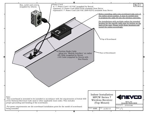
4Box, outlet and cover(supplied by others)3Power Cord:-6' 7" Power Cord 110 VAC (supplied by <strong>Nevco</strong>)-Optional 15' Power Cord (009-0324) available from <strong>Nevco</strong>-Optional 6' 7" Power Cord 220 VAC (009-0257) available from <strong>Nevco</strong>21RevCDBefore installing radio onto scoreboard take note ofthe radios serial number. It may be needed laterto program the radio ID into the wireless controller.For installations with multiple radios the intendedlocation for the specific radio may be written on theback of the case. Please verify these locations andinstall the radios accordingly.DTop of ScoreboardCC6 Position Radio Cable(plug into "Module Interface" on radio)-5ft Cable (supplied by <strong>Nevco</strong>)-14ft Cable (supplied by <strong>Nevco</strong>) withStat PanelsFace of ScoreboardBBANote:-This scoreboard is intended to be installed in accordance with the requirements of Article 600of the National Electrical Code and/or other applicable local codes. This includesproper grounding and bonding of the scoreboard.-For power requirements see the scoreboard installation print for the model of scoreboardbeing installedDrawnIndoor <strong>Installation</strong>MPCW Series 7Wireless Receiver(Top Mount)DateMMK 2/25/13Drawing No.Sheet of<strong>Nevco</strong>, Inc.Greenville, Illinois 622461 1275-0166A4321
DDisplay Connections43Box outlet and cover:- Supplies power to scoreboard,message center and POE.- (supplied by others)- Power cords for scoreboard and POEare supplied by <strong>Nevco</strong>.2Wireless Receiver(scoreboard)1RevAPhone Cable 2' long fromreceiver to scoreboard.(supplied by <strong>Nevco</strong>)DClient Bridge- for lower message center- see sheet 3 for mountingCAEthernet from ClientBridge to POE "POE"(25').CEthernet Crossoverfrom LAN-IN on POEto message centerSignal-In (25')Power Over EthernetSupply (see detailview of on sheet 2)DETAIL ANotes:1. Remove nearby access panel tomake signal connection (signalconnection located insided cabinet)BCarefully Remove knockoutin panel to make connection.2. Panel may be placed on bottomof message center on this side. Seedetail to right.BBEthernet crossoverto message centerSignal-InFeed panel through holeas shown to changelocation of power/signalinpanel.A43DETAIL BDrawnHybrid 16mm/20mmWireless Indoor SignalConnections2DateDBB 04/07/10Drawing No.Sheet of<strong>Nevco</strong>, Inc.Greenville, Illinois 622461 3275-05761A
D4Control Room ConnectionsD3Client Bridge2AccessPoint1RevARemove cover andplug into ethernetport closest to thecenter of the accesspoint.DClient BridgeSignal strength metershould have 3 bars lightedfor adequate signalSee important note belowAccess PointCC3' crossover fromPOE to PC.3' Crossover Cable(color coded red)"POE"StraightThrough Cable(color codedwhite)"LAN"BA4Power cord for POE(supplied by <strong>Nevco</strong>)ImportantWireless devices should be in Clear Line of Sight from each other. Penetration ofobstacles by the wireless signal is dependant on the material of the obstacle as wellas the overall distance between devices.3Note: Refer to drawing276-0671 for scoreboardand VSBI connectioninstructions.DrawnHybrid 16mm/20mmWireless Indoor SignalConnections2DatePower OverEthernetSupplyDrawing No.Sheet ofDBB 04/07/10 2 3<strong>Nevco</strong>, Inc.Greenville, Illinois 62246275-05761BA