Nevco Scoreboard Company Installation Manual
Nevco Scoreboard Company Installation Manual
Nevco Scoreboard Company Installation Manual

You also want an ePaper? Increase the reach of your titles
YUMPU automatically turns print PDFs into web optimized ePapers that Google loves.
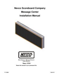
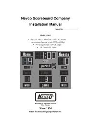
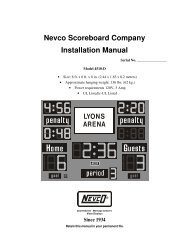
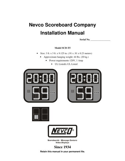
<strong>Nevco</strong> <strong>Scoreboard</strong> <strong>Company</strong><strong>Installation</strong> <strong>Manual</strong>Serial No. ________________Model SCD-T5• Size: 3 ft. x 3 ft. x 9.125 in. (.91 x .91 x 0.23 meters)• Approximate hanging weight: 44 lbs. (20 kg.)• Power requirements 120V, 1 Amp• UL Listed/c-UL ListedSince 1934Retain this manual in your permanent file.
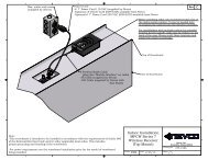
Thank YouThank you for purchasing from <strong>Nevco</strong><strong>Scoreboard</strong> <strong>Company</strong>. Below are some importanttips to remember when installing your newequipment.• Pre-test the equipment before installation.• Consult National Electrical Code and localcodes before installation.<strong>Installation</strong> InstructionsUnpacking the EquipmentTo protect your new scoreboard system fromaccidental damage, follow the steps below: Carefully remove all equipment from itspacking carton. Do not pry against thescoreboard in any way. Inspect for damage.Note: If damage to any equipment contactcarrier immediately.There is an electronic module located insideeach shot clock. Consult the includeddrawings for the exact location and accessmethod.Make sure all plugs are firmly seated in theirproper sockets. If some cables are loose ordisconnected, refer to Module Illustration.This print identifies the function of eachmodule plug and shows where to connect thecables.Pre-Test Your Equipment(SCD-T5 Pre-Mounting Test)Connect a length of 2-WIRE cable from theBNC connector on the end of the moduleinside the shot clock to your signal source.(control or receiver) (See installation printfor module location)Connect the shot clock to a temporary powerservice. (See installation print for powerservice requirements.)Follow the Control Hookup & Testing Guideto make sure the system operates properlybefore installing the scoreboard.<strong>Scoreboard</strong> MountingThe installation print shows the mounting centersand location of power. The mounting bracketshave a slot 1 ½ in. by ½ in. wide.Secure at all mounting brackets provided.The shot clocks are equipped with a splice boxfor use with conduit.Always use good mechanical practices whenmounting the shot clocks:• Use a flat washer and lock washer with aminimum 3/8” bolt to prevent vibration fromloosening the fastening device.• Use only plated fastening devices to preventrust or corrosion.Power Service ConnectionsThe power service for each shot clock is 120V,1A, 50/60HZ. This allows a 20 per cent safetyfactor to eliminate nuisance tripping of thecircuit breaker. To eliminate service problems atsome future date and the possibility ofoverloading the circuit breaker, we suggestinstalling a dedicated service or circuit for theshot clocks. The contractor or installationpersonnel will determine length and size of thewire to maintain the voltage needed to supportthe circuit load. We recommend the powerservice maintain 120V at the shot clock undermaximum load.If conditions permit, the owner may place thepower service and the 2-WIRE control cable inthe same conduit. The 2-WIRE cable has adielectric strength of 300 volts or better. Consultthe National Electrical Code and local codes forthe installation of Class 2 wiring.
WIRED INSTALLATIONMake connection from BNC connector on end ofmodule inside the Shot Clock to control point.(junction boxes provided)WIRELESS INSTALLATIONRun coaxial cable provided from BNC connectoron end of module inside the Shot Clock to thereceiver location.Installing Cable ConnectorsThe 2-WIRE cable that comes with yourscoreboard does not have connectors attached.14 "916 "Insulating boot132 "To install connectors on each end of the cable:Slide the insulating boot onto the cable andtrim the cable as shown.Twist the outer braid in a clockwise directionso that at least 1/32 in. of the inner dielectricis bared and the braid is left flat. Be sure nostrands of the outer braid are touching thecenter conductor.Insert the center conductor into the back ofthe connector, feeding it into the guide hole.Push the cable as far as possible into theconnector.Screw the connector onto the cable in aclockwise direction until the connector stopsturning.Slip the insulating boot over the back of theconnector.
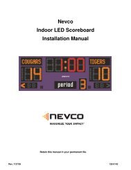
<strong>Nevco</strong> <strong>Scoreboard</strong> <strong>Company</strong><strong>Scoreboard</strong> Testing and Troubleshooting GuideSCD-5TSince 1934Retain this manual in your permanent file.
<strong>Scoreboard</strong> Module and Operation TestingBecause the microcomputer is capable of “masking” weaknesses in the scoreboard system, it is importantthat it reveal problems so corrections can be made before they get worse. A special command can be sentfrom the control to start the scoreboard self-test program. Please consult the Control Hookup andTroubleshooting Guide for instructions on initiating and terminating the following tests.Control Signal TestConsult the Control Hookup and Troubleshooting Guide for availability and instructions.<strong>Scoreboard</strong> Self-testConsult the Control Hookup and Troubleshooting Guide for instructions on initiating this test.Light Circuit TestWhen the <strong>Scoreboard</strong> Self-test is started, an “E” will appear in the Main Time Seconds Unit’s section ofthe SCD-5T for about a second before the Light Circuit Test starts. One LED segment will illuminate inall digits in succession for two rotations. An eight will then display in one digit at a time for tworotations. Next the End Of Period segments will be tested. This pattern will continue until you eitherreestablish communications from the control or turn off the power to the scoreboard.Make careful note of any LED segments that are not illuminating. Contact <strong>Nevco</strong> Service Department forhelp.
Troubleshooting GuideA shot clock malfunction normally results from a component failure or a bad mechanical connection.This troubleshooting guide helps to locate the failure. This information can then be reported to the <strong>Nevco</strong>Service Department.NOTE: Turning the control off does NOT turn the power off to the scoreboard or other devices.PROBLEM:The shot clock does not illuminate even though the control seems to operate correctly.SOLUTION:Check the circuit breakers associated with the shot clock.Check all 2-WIRE cables and connections.Make sure all necessary hand held switches are connected to the control. (Some controls require ahand held shot clock switch in order to access the shot clock functions).Consult the Control Hookup and Troubleshooting Guide for more help.PROBLEM:Control does not respond when turned on and the shot clock does not illuminate.SOLUTION:See Control Hookup and Troubleshooting Guide.PROBLEM:A single segment in a particular numeral does not light.SOLUTION:Turn the power service to the scoreboard off.NOTE: Power is still applied to the scoreboard module(s) even with the control turned off.Refer to module illustration print, which shows module plug numbers and their use. Locate the plugthat is not working properly. Check the plug for firm connection.Interchange the plug in question with a plug that is known to work:
If the LED segment lights after exchanging plugs, the problem is in the module. Return the module tothe <strong>Nevco</strong> Service Department for repair.If the segment remains unlit, the problem is in the LED unit or the segment itself. Make note ofsegment location and contact the <strong>Nevco</strong> Service Department.PROBLEM:One or more segments do not turn off when the control is turned off.SOLUTION:A problem exists in the module. Carefully document the location of the segments and return thedefective module to the <strong>Nevco</strong> Service Department.If the problem persists please contact the <strong>Nevco</strong> Service Department.800-851-4040
<strong>Nevco</strong> Guarantee<strong>Nevco</strong> scoreboards are guaranteed for a period of five (5) years** from the date of invoice against defectsin workmanship or material and will be replaced or repaired without cost to the owner provided theequipment or parts (which includes LED segments) are returned postage-paid to the <strong>Nevco</strong> factory.Shipping back to the owner will be surface postage prepaid except if air or special method of return isspecified; then shipping will be freight collect. Lamp bulbs are excluded from this guarantee. <strong>Nevco</strong><strong>Scoreboard</strong> <strong>Company</strong> will pay no charges for time or material used by others in making repairs orcorrections. Guarantee shall be void if: any alteration or service, other than unplugging modules orcontrols, is performed without <strong>Nevco</strong> factory authorization; or if the equipment has been connected toincorrect power, or is improperly grounded or improperly installed. Equipment which is subjected toaccident, neglect, abuse, misuse or other natural disasters, including but not limited to: fire, wind,lightning, flood, is not covered by this guarantee.** <strong>Nevco</strong> wireless equipment is guaranteed for a period of two (2) years from the date of invoice. . Allother terms and conditions of this guarantee remain the same.-----------------------------------------------------------------------------------------NEVCO SCOREBOARD COMPANY301 East Harris AvenueGreenville, IL 62246-2151 USATelephone: 618-664-0360Fax: 618-664-0398TOLL-FREE 800-851-4040From all 50 states and Puerto Rico— IN CANADA —NEVCO SCOREBOARD COMPANY ULC107 Forestview Rd., P.O. Box 2629Orillia, ON L3V 7C1 CanadaToll Free: 800-461-8550Fax: 705-325-8891Website: www.nevco.comEmail: info@nevco.comSince 1934NOTE: This equipment has been tested and found to comply with the limits for a Class A digital device, pursuant to part 15 of the FCC Rules. These limits are designed to providereasonable protection against harmful interference when the equipment is operated in a commercial environment. This equipment generates, uses, and can radiate radio frequencyenergy and, if not installed and used in accordance with the instruction manual, may cause harmful interference to radio communications. Operation of this equipment in a residentialarea is likely to cause harmful interference in which case the user will be required to correct the interference at his own expense.This class A digital apparatus meets all requirements of the Canadian Interference- Causing Equipment Regulations.Cet appareil numerique de la classe A repecte toutes les exigences du Reglement sure le materiel brouller du Canada.
Service Request<strong>Scoreboard</strong> Serial # ________________________________________________________________________Service: Module(s) Serial # __________________________________________________________________Service: Control(s) Serial # __________________________________________________________________Comments:__________________________________________________________________________________________________________________________________________________________________________________________________________________________________________Parts RequestQuantity Part No. Description1. ________ ______________________ ___________________________________________________2. ________ ______________________ ___________________________________________________3. ________ ______________________ ___________________________________________________4. ________ ______________________ ___________________________________________________5. ________ ______________________ ___________________________________________________Contact, Shipping, and Billing InformationPerson to Contact:________________________________________ Phone # _______________________E-Mail:_________________________________________________________________________________Ship To:_________________________________________________________________________________Street __________________________________________________________________________City_____________________________________ State _______ Zip Code ________________Ship Via ________________________________________________________________________Bill To: ________________________________________ Purchase Order # ______________________P.O. Box #______________________________________________________________________Street __________________________________________________________________________City______________________________________ State ______ Zip Code _______________We will contact you with the amount of your purchase before charging your account.Charge To: ______________________________________Name exactly as it appears on credit card_____________________________________SignatureCredit Card: American Express MasterCard VISA_________-_________-_________-_________Expiration Date: _____/_____Credit Card Account Number Month YearMake a copy of this form to order parts needed and/or to return with item to be serviced.