Nevco Indoor LED Scoreboard Installation Manual
Nevco Indoor LED Scoreboard Installation Manual
Nevco Indoor LED Scoreboard Installation Manual
- No tags were found...

You also want an ePaper? Increase the reach of your titles
YUMPU automatically turns print PDFs into web optimized ePapers that Google loves.
3. Electrical ConnectionsPower Service Consult the table on the installation print for power requirements for your scoreboard model. Provide for a 40%safety factor to guard against tripping of the circuit breaker under low line conditions. Be sure to include any lighted signs, and message centers when sizing the supply wiring necessary to supportthe circuit load. The person performing the installation should be familiar with National and local electric codes. A standard IEC US grounded power cord is shipped with the board for attaching power. The power connection is low-profile to allow for flush mounting of signs and message centers.Signal ConnectionsRefer to wireless receiver installation prints for receiver mounting and connections.Connect the coax input to the BNC marked “Input”.A right angle BNC adapter can be used to allow for flush mounting of signs and message centers.The BNC marked “Output” can be used to drive other scoreboards sharing the same display data.This allows scoreboards to be daisy-chained together, or the output can be used to supply signal to accessoriessuch as a shot clock or end of period indicator. By adding a “T” connector at this location, two accessories canbe connected at once with up to 1000 ft . of coax each.2-Wire Coax Cable (RG58/U)All 2-WIRE cable ordered from <strong>Nevco</strong> is direct burial type. It has a minimum dielectric strength of 300V, andconforms to UL standard 1365.If the wiring is buried above the freeze line, bury the cable with sand to provide drainage and prevent damage fromshifting soil.Installing Cable ConnectorsThe 2-WIRE cable that comes with your scoreboard does not have connectors attached.To install connectors on each end of the cable:Slide the insulating boot onto the cable and trim the cable as shown.Twist the outer braid in a clockwise direction so that at least 1/32 in. of theinner dielectric is bared and the braid is left flat. Be sure no strands of theouter braid are touching the center conductor.Insert the center conductor into the back of the connector, feeding it into theguide hole.Push the cable as far as possible into the connector.Screw the connector onto the cable in a clockwise direction until the connectorstops turning.Slip the insulating boot over the back of the connector.14 "916 "Insulating boot132 "Page 2
WIRED TROUBLESHOOTING GUIDEThe figure to the rightlabels the connectionsfrom A – M. The chartbelow lists the problemthat can be identifiedshould any connectionbe faulty. Check thecontrol and servicemanual for more detailedinformation.NOTE: The number thatappears above a letterrefers to the number ofwires or conductors inthe cable.BranchCircuitControl3A2 (coax)BPowerSupply<strong>Scoreboard</strong>Interface4C8DILM-2SIC1-8BLHornsETNMasterDigit8E2I2HornK 6L10FDriverBacklightsHome/Guest8H10G2J6MSlaveDigitTo NextDigitTo NextBacklightTo NextETN PanelSituation Symptom Connection SolutionThe <strong>Scoreboard</strong>has no digitsilluminatedSome digits notilluminated, ornon-workingaccessoryWhen power is first applied the timer section does notrotate through a test patternWhen power is first applied the timer section rotatesthrough a test pattern, but then the display goes out.ACEBDCheck branch circuit breaker and power connectionsCheck connection on ILM and power supply terminal screwsCheck connection to first digit in timer sectionCheck Coax connections. Plug control directly into the top of the board toeliminate installed coax cable. If that works, the cable run or terminations arebad. Try the 301 Model code, see control users manual on testing.Check connections on inside of board at the SIC and at the ILMOnly one digit F / G / H Check 10-pin connection on Driver card and 2-pin on single segmentsHorn K Check 2-pin connection on ILM and at horn (2 horns ea.)Backlight channelsI / JCheck 2-pin connection on ILM and at backlight. Check instructions to see ifthe backlights are supposed to be ON.All or partial ETN’s not working L / M Check 6-pin connection from ILM to ETN and between ETN panelsPage 4
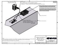
Wireless Troubleshooting GuideThe figure to the right labels connections (A – E) useful to troubleshooting. The chartbelow lists the problem that can be identified should any connection be faulty. Checkthe control and service manual for more detailed information.NOTE: The number that appears above a letter refers to the number of wires orconductors in the cable.ControlBranchCircuit3 DPowerAdapter0900MhzE2CReceiver3A2 (coax)BSame diagram andtroubleshooting from “WiredTroubleshooting Guide”Situation Symptom Connection SolutionThe<strong>Scoreboard</strong>has no digitsilluminatedSome digits notilluminated, ornon-workingaccessoryWhen power is first applied to the board the timersection does not rotate through a test patternWhen power is first applied the timer sectionrotates through a test pattern, but then the displaygoes out.Receiver has No <strong>LED</strong>s illuminated during first 5 seconds afterpower upReceiver <strong>LED</strong> Not ON solidAOtherBADCECheck branch circuit breaker and power connectionsSee “Wired Troubleshooting Guide”Check Coax connections. Plug control directly into the top of the board. Try the 301Model code, see control users manual on testing.Check branch circuit breaker and power connectionsIf the duplex receptacle has power, but the adapter <strong>LED</strong> is OFF, replace adapterEnsure DC plug is fully seated in receiver DC jack and making good connectionReplace ReceiverFollow control troubleshooting procedures, wrong wireless group, etc.Receiver should be in clear line of sight from control.See “Wired Troubleshooting Guide” Other See “Wired Troubleshooting Guide”Page 5
NEVCO GUARANTEE<strong>Nevco</strong> scoreboards, marquees and message centers are guaranteed for a period of (5)years* from the date of invoice against defects in workmanship or material and will bereplaced or repaired without cost to the owner provided the equipment or parts (whichincludes <strong>LED</strong> segments) are returned postage-paid to the <strong>Nevco</strong> factory. Shipping backto the owner will be surface postage prepaid except if air or special method of return isspecified, then shipping will be freight collect. Incandescent lamp bulbs are excludedfrom this guarantee. <strong>Nevco</strong> will pay no charges for time or materials used by others inmaking repairs or corrections. Guarantee shall be void if: any alteration or service, otherthan unplugging modules or controls, is performed without <strong>Nevco</strong> factory authorization;or if the equipment has been connected to incorrect power, or is improperly grounded orimproperly installed. Equipment which is subjected to accident, neglect, abuse, misuseor other natural disasters, including but not limited to: fire, wind, lightning, flood is notcovered by this guarantee.*Wireless components, Solar kit and the UltraScore portable scoreboard carry a two year guarantee.— IN USA —NEVCO, Inc.301 East Harris AvenueGreenville, IL 62246-2151 USATelephone: 618-664-0360Fax: 618-664-0398TOLL-FREE 800-851-4040From all 50 states and Puerto Rico— IN CANADA —NEVCO, ULC107 Forestview Rd., P.O. Box 2629Orillia, ON L3V 7C1 CanadaToll Free: 800-461-8550Fax: 705-325-8891Website: www.nevco.comEmail: info@nevco.comNOTE: This equipment has been tested and found to comply with the limits for a Class A digital device, pursuant to part 15 of the FCC Rules. These limits are designedto provide reasonable protection against harmful interference when the equipment is operated in a commercial environment. This equipment generates, uses, and canradiate radio frequency energy and, if not installed and used in accordance with the instruction manual, may cause harmful interference to radio communications.Operation of this equipment in a residential area is likely to cause harmful interference in which case the user will be required to correct the interference at his ownexpense.This class A digital apparatus meets all requirements of the Canadian Interference- Causing Equipment Regulations.Cet appareil numerique de la classe A repecte toutes les exigences du Reglement sure le materiel brouller du Canada.Page 6
Service Request<strong>Scoreboard</strong> Serial # ________________________________________________________________________Service: Module(s) Serial # __________________________________________________________________Service: Control(s) Serial # __________________________________________________________________Comments:__________________________________________________________________________________________________________________________________________________________________________________________________________________________________________Parts RequestQuantity Part No. Description1. ________ ______________________ ___________________________________________________2. ________ ______________________ ___________________________________________________3. ________ ______________________ ___________________________________________________4. ________ ______________________ ___________________________________________________5. ________ ______________________ ___________________________________________________Contact, Shipping, and Billing InformationPerson to Contact:________________________________________ Phone # _______________________E-Mail:_________________________________________________________________________________Ship To:_________________________________________________________________________________Street __________________________________________________________________________City_____________________________________ State _______ Zip Code ________________Ship Via ________________________________________________________________________Bill To: ________________________________________ Purchase Order # ______________________P.O. Box # ______________________________________________________________________Street __________________________________________________________________________City______________________________________ State ______ Zip Code _______________We will contact you with the amount of your purchase before charging your account.Charge To: ______________________________________Name exactly as it appears on credit card_____________________________________SignatureCredit Card: American Express MasterCard VISA_________-_________-_________-_________Expiration Date: _____/_____Credit Card Account Number Month YearMake a copy of this form to order parts needed and/or to return with item to be serviced.Page 7
<strong>Nevco</strong>Message Center<strong>Installation</strong> <strong>Manual</strong>Retain this manual in your permanent file.6/01/2009 135-0144
Table of ContentsINSTALLATION INSTRUCTIONS ............................................................................... 1UNPACKING THE EQUIPMENT....................................................................................... 1MESSAGE CENTER MOUNTING..................................................................................... 1MESSAGE CENTER CONNECTIONS............................................................................... 3Electrical Connections................................................... Error! Bookmark not defined.Power Service.......................................................................................................................................................4Ethernet Cables ................................................................................................ 4. SOFTWARE SETUP .................................................................................................... 5Computer is Not connected to existing Network......................................................... 5Computer is Connected to an existing Network.......................................................... 6INSTALLER’S TROUBLESHOOTING GUIDE ............................................................ 7GLOSSARY ............................................................................................................... 9
<strong>Installation</strong> Instructions<strong>Installation</strong> consists of four steps, Unpacking the Equipment, Message Center mounting, Connections, andSoftware setup. Be sure to read and understand all of the instructions before installing the equipment. Consultthe “installer’s trouble shooting guide” following this section for verifications each step has been installed andis working correctly.1. Unpacking the Equipment Inspect the shipping container for damage. If any damage can be seen, contact the carrierimmediately. Carefully remove all equipment from its packing carton. Do not pry against the message centerin any way.2. Message Center Mounting <strong>Nevco</strong> strongly encourages you to check local codes before beginning the installation. You maywish to contact a local architect, contractor, or sign installer for assistance. Your <strong>Nevco</strong> SalesRepresentative may be able to assist you in finding professional installers who are familiar withthis type of equipment. Always use good mechanical practices when mounting the message center. Use plated fastening devices to prevent rust or corrosion. Mount the optional temperature sensor / photocell out of direct sunlight to avoid an elevatedreading. Mount the two wireless devices (if present) in clear line of sight with each other.Your Message Center was designed so that it can be mounted in a variety of ways. Pleaseexamine the installation drawings to determine the best mounting method for your location.Access to all internal components is through the front, accessibility to the rear of the cabinet isNOT necessary. The standard mounting brackets are shipped on the Message Center in a“retracted” position and must be unbolted and rotated 180°, then reattached with the same boltsbefore starting the installation.Note: Please securewith two (2) fasteners ateach mounting bracketlocation.Shipping PositionMounting PositionWall Mount135-0144 Page 1
Additional Suggested Mounting MethodsFlush MountTubing MountNote: Please see installation drawings for more details and options.135-0144 Page 2
3. Message Center ConnectionsEach message center, whether it is made up of two cabinets end to end, or two cabinets back to back(double sided), or a single cabinet, requires that power and signal be supplied to each cabinet by theinstaller. All internal connections have been completed and tested at the factory.Both power and data should enter each message center cabinet at its lower right corner. An access panelis provided for these connections. The “signal in” conduit attaches to thepanel and a junction box is mounted on the panel for power connections.Similar access panels are installed on the back and bottom of the cabinet. Allthree panels are interchangeable so that the one with the junction box can belocated in the most favorable position. The panel with the junction box can bemoved to either of the other locations without disconnecting any cables insidethe message center.Be sure to reattach all panels so as to maintain a weather tight seal.The optional temperature and light sensors should be mounted near this location and need to beconnected to a cable inside the message center behind the access panel.At the lower left corner of the message center is a similar arrangement for the“signal out” if needed. Used for side 2 of a two sided message center, and messagecenters made up of two cabinets mounted end to end.Note: Please see installation drawings for more details.135-0144 Page 3
Electrical ConnectionsRefer to installation prints for illustration ofelectrical connections.Power ServiceThis sign is intended to be installed inaccordance with the requirements ofArticle 600 of the National ElectricalCode and/or other applicable local codes.This includes proper grounding and bondingof the sign.Consult table 1 for power requirements for yourmessage center model. Provide for a 30% safetyfactor to guard against tripping of the circuitbreaker under low line conditions.*Denoted values require 2 separate 20A breakers.20mmColor32mmMonoCabinetDimensionsCurrent @120VACCurrent @240VAC3x8 9.6 4.83x10 12.3 6.23x12 15.0 7.54x8 13.4 6.74x10 17.3 8.64x12 Left End 9.6 4.84x12 Right End 11.5 5.84x16 Left End 13.4 6.74x16 Right End 15.3 7.74x16 Left End 6.3 3.24x16 Right End 6.3 3.2Table 1 Be sure to include any lighted signs, and account for double sided displays when sizing the supply wiringnecessary to support the circuit load. A disconnect switch should be lockable or within sight of the sign per NEC article 600.Ethernet CablesIn a wired configuration, connect from the PC to the controller with a crossover connection.Use ¾” rain-tight conduit fittings to avoid cutting the ends off the included pre-made cables.WARNING! Take care not to reverse the connections on the POE adapter as this will damage the controller.Refer to installation print and color coding for details.The diagrams below show Ethernet connections:• Ethernet Straight through cable• Ethernet Crossover cablePCPOEWirelessAP2.4GhzWirelessWirelessBridgePOERain-tight BoxFigure 1 – Wireless ConfigurationTRSign Sign Side 2if double sidedPC Sign Sign Side 2Less than 325’Figure 2 – Wired Configuration EthernetTRif double sidedPC Media ConverterSign Sign Side 2Fiber 325’ – 1.2 MilesMedia ConverterRain-tight Box135-0144Figure 3 – Wired Configuration Fiber OpticPage 4TRif double sided
4. Software SetupThe message center can b e connected to a dedicated co mp uter for setting up new messages, or integrated as p artof an existing comp uter network. The sy stem is shipp ed in the first case as described in “Not connected toexisting Network”.Computer is Not connected to existing NetworkThe message center controller and wireless equip ment (op tional) are p re-configured to a d efault networkconfiguration. The IP address of the controller is set to 192.168.0.210. Wireless Brid ge and AP are192.168.0.211 and 192.168.0.212 resp ectively .When the software is installed, the default p rojects are configured to talk to the default controller IP address.Follow these step s to set the controlling PC’s IP address to one that can communicate with the messagecenter.1. Click the start button and select Control Panel. Double click Network Connections. Double click y ournetwork card or “Lan Connection”. On Win XP select p rop erties. You will see the window on the left.Select Internet Protocol (TCP/IP) and click Prop erties. You will see the window on the right.2. Click the Radio Button “Use the following IP address” and enter 192.168.0.10 and the subnet mask255.255.255.0 and click ok on each window. You may be p romp ted to insert y our Win98/2000 CD.3. When y ou op en <strong>Nevco</strong> Comp oser, the button in the lower right hand corn er of the screen should say“Up date M essage Center” showin g that y ou are connected. (Be sure the license key is in the USB p ortand the <strong>LED</strong> is on)4. Consult the <strong>Nevco</strong> Comp oser user’s manual for troubleshooting.If y ou are using a lap top , make sure to turn off the wireless LAN in the laptop (if p resent). This can be doneon most laptop s by p ressing a button in the area above the key board that looks like an antenna.135-0144 Page 5
Computer is Connected to an existing NetworkThe message center controller and wireless equip ment (optional) are p re-configured to a default networkconfiguration. The IP address of the controller is set to 192.168.0.210. Wireless Bridge and AP are192.168.0.211 and 192.168.0.212 resp ectively .The step s to change the IP address one each of the devices are exp lain ed in detail in the user’s manuals foreach dev ice. Consult these manuals for more information. The wireless devices supp ort DHCP, but themessage center’s IP address must be static. To integrate the equip ment into y our existing network, in thisorder y ou must change the IP address on a comp uter, use that comp uter to change the message center IPaddress, chan ge the outdoor bridge IP address, and then chan ge the Access Point IP address. Follow thesestep s:1. Connect the access p oint to the LAN with a straight through Ethernet cable. The unit is shipp ed with acrossover cable for connectin g directly to a PC.2. Change a PC on the network’s IP address as instructed in “Not connected to an existing Network”above.3. Change the M essage Center’s IP address by following these step s.a. Install <strong>Nevco</strong> Comp oser on the Comp uter. Be sure to p lug the license key into the USB p ort.b. Enter “Password” as instructed in the manual. As long as the p assword remains “Password” y ouwill be p romp ted to change it each time the p rogram is load ed.c. Go to M essage Center=>Configure Password and M essage Centerd. Enter y our current p assword and click conn ect on the right hand side of the window.e. Enter the new IP address and subnet mask and click Up date.4. Change the Outdoor wireless client’s IP address by following these step s.a. Op en internet exp lorer and in the Address Bar typ e 192.168.0.211b. Refer to the sticker in y our user’s manual for the username and p assword.c. A web p age called W ireless Client Brid ge will come up . Click on “TCP/IP Settings” and select“LAN Interface”.d. Change the network settings as necessary to fit y our network top ology and click “App lyChanges”.e. You may also want to change the wireless settings to suit y our own security needs. Be sure tochan ge the Access Point to match in the next section.5. Change the Access Point’s IP address by following these steps.a. Op en internet exp lorer and in the Address Bar typ e 192.168.0.212b. Refer to the sticker in y our user’s manual for the username and p assword.c. A web p age called W ireless LAN Access Point will come up .d. Follow the same steps as 4, steps c - e. M ake sure any security settings chan ged on the ClientBridge match settings on the Access p oint.6. You may now chan ge y our PC’s IP address back to its original configuration. Test the newconfiguration by op ening <strong>Nevco</strong> Comp oser, goin g to Project=>Configure, enter the new IP address ofthe message center and click “OK”. The status at the bottom of the screen should now be “Disp layConnection = Ethernet”.135-0144 Page 6
INSTALLER’S TROUBLESHOOTING GUIDEThe figure below labels the connections made by the installer from A – K. The chart below lists the problem thatcan be identified should each connection be faulty. Should a problem arise on any one component, consult thetrouble shooting guide specific to that device..Note: All connections inside the Message Center have been made at the NEVCO Factory. Each MessageCenter requires Signal from the controlling PC. Each Message Center also requires Power (see Table 1).Note: For double sided and/or double cabinet message centers. The input signal for subsequent cabinets comesfrom the output of the previous cabinet. A separate power circuit is required for each cabinet.MESSAGE CENTERAJHGFDTemperature & LightSensorsCPCPOEJPowerWirelessAP2.4GhzWirelessWirelessBridgePOEEPowerEthernet InBPower InKEthernet OutTo side 2(if applicable)Rain-tight BoxIf Outdoors135-0144 Page 7
Situation Symptom Connection SolutionThe messageCenter is notdisplaying amessageI cannotcommunicatewith themessagecenterPart ofmessagecenterappears“dead”The fans on ALL power supplies arerunningThe fans on ALL power supplies are notrunningOn a double sided Message Center, Oneside is displaying the message, the otheris not“ DSP” <strong>LED</strong> on controller IS blinking,but the CASCAN card has no <strong>LED</strong>’sblinking rapidly (like DSP on thecontroller).No Red Power <strong>LED</strong> lit on WirelessBridge POE.No Red Power <strong>LED</strong> lit on WirelessAccess Point POE.LAN <strong>LED</strong> on Controller not ON solidLAN <strong>LED</strong> on PC Ethernet port not ON,or PC says “ network unplugged”, “notconnected”.User’s manual on CD with wirelessequipment explains how to measure thewireless signal strengthOnly part of message center will lightC,DBK,cDEJDFHIGReplace crossover cableIn Composer, check the scheduling for the Project, thenclick the button to send the project to message centerCheck Power Switch on disconnect box inside messagecenterCheck connections in disconnect box (power hookup)Check branch circuit; was there a photocell on an existingsign install?Ensure an Ethernet straight through cable has been used, ismaking a good connection at both ends.Ensure an Ethernet crossover cable has been used, ismaking a good connection at both ends.Check branch circuit and power at the receptacle. Adapterhas <strong>LED</strong> indicatorCheck branch circuit and power at the receptacle. Adapterhas <strong>LED</strong> indicatorEnsure an Ethernet crossover cable has been used and ismaking a good connection at both endsEnsure an Ethernet straight through cable has been used andis making a good connection at both ends.Ensure an Ethernet straight through cable has been used andis making a good connection at both ends.Ensure an Ethernet crossover cable has been used and ismaking a good connection at both ends. Check to see thatthe network interface is enabled and follow the procedure in“Not connected to existing Network above.Reorient the wireless device’s antennas to eliminateobstructions between themIn Composer, check the zone section to make sure theproject is set to use the whole message centerTemperature Not installed A Install sensor in message centerSensor doesNOT work Not enabled Make sure the temperature sensor is enabled in ComposerLight Sensordoes NOTNot installed A Install sensor in message centerwork Not enabled Make sure the light sensor is set to auto in ComposerIf the problem persists please contact the <strong>Nevco</strong> Service Department.800-851-4040135-0144 Page 8
GLOSSARYACCESS POINT (WIRELESS AP)A hardware device that allows wirelesscommunication devices to connect to anetwork.Can also be configured as aWIRELESS BRIDGEA hardware device used to connect two ormore network segments.ACCESS POINTCASCAN cardDistributes the data inside the MessageCenter.CASCAN card135-0144 Page 9
DISPLAY PanelA group of pixels. Several Display Panels are combined to form the message center.DSPDigital Signal Processing.PIXELA group of one or more <strong>LED</strong>s.POEPower Over Ethernet.Used to inject power for use byA device connected to theEthernet cable.POEPOWER SUPPLYConverts the line voltage to 12 volts or 5 volts.POWER SWITCHDisconnects power to a portion of the message center components. Cabinet may contain more than one.RIBBON CABLEFlat 16 conductor cable used to carry the data from the CASCAN card to the display panels and from display panel todisplay panel.WIRELESS BRIDGEA hardware device used to connect two or more network segments. (See Access Point)135-0144 10Page 10
X-6 (CONTROLLER)Stores, processes, and distributes the message center data to the CASCAN card(s).X-6 CONTROLLERX-6 CONTROLLER with power supply135-0144 11Page 11
Notes12