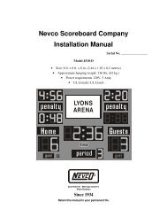
Nevco Indoor LED Scoreboard Installation Manual
Nevco Indoor LED Scoreboard Installation Manual
Nevco Indoor LED Scoreboard Installation Manual
- No tags were found...

Create successful ePaper yourself
Turn your PDF publications into a flip-book with our unique Google optimized e-Paper software.
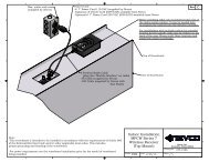
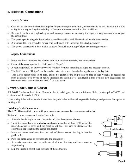
3. Electrical ConnectionsPower Service Consult the table on the installation print for power requirements for your scoreboard model. Provide for a 40%safety factor to guard against tripping of the circuit breaker under low line conditions. Be sure to include any lighted signs, and message centers when sizing the supply wiring necessary to supportthe circuit load. The person performing the installation should be familiar with National and local electric codes. A standard IEC US grounded power cord is shipped with the board for attaching power. The power connection is low-profile to allow for flush mounting of signs and message centers.Signal ConnectionsRefer to wireless receiver installation prints for receiver mounting and connections.Connect the coax input to the BNC marked “Input”.A right angle BNC adapter can be used to allow for flush mounting of signs and message centers.The BNC marked “Output” can be used to drive other scoreboards sharing the same display data.This allows scoreboards to be daisy-chained together, or the output can be used to supply signal to accessoriessuch as a shot clock or end of period indicator. By adding a “T” connector at this location, two accessories canbe connected at once with up to 1000 ft . of coax each.2-Wire Coax Cable (RG58/U)All 2-WIRE cable ordered from <strong>Nevco</strong> is direct burial type. It has a minimum dielectric strength of 300V, andconforms to UL standard 1365.If the wiring is buried above the freeze line, bury the cable with sand to provide drainage and prevent damage fromshifting soil.Installing Cable ConnectorsThe 2-WIRE cable that comes with your scoreboard does not have connectors attached.To install connectors on each end of the cable:Slide the insulating boot onto the cable and trim the cable as shown.Twist the outer braid in a clockwise direction so that at least 1/32 in. of theinner dielectric is bared and the braid is left flat. Be sure no strands of theouter braid are touching the center conductor.Insert the center conductor into the back of the connector, feeding it into theguide hole.Push the cable as far as possible into the connector.Screw the connector onto the cable in a clockwise direction until the connectorstops turning.Slip the insulating boot over the back of the connector.14 "916 "Insulating boot132 "Page 2