Nevco Indoor LED Scoreboard Installation Manual
Nevco Indoor LED Scoreboard Installation Manual
Nevco Indoor LED Scoreboard Installation Manual
- No tags were found...

You also want an ePaper? Increase the reach of your titles
YUMPU automatically turns print PDFs into web optimized ePapers that Google loves.
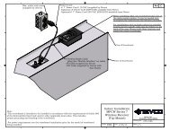
3. Message Center ConnectionsEach message center, whether it is made up of two cabinets end to end, or two cabinets back to back(double sided), or a single cabinet, requires that power and signal be supplied to each cabinet by theinstaller. All internal connections have been completed and tested at the factory.Both power and data should enter each message center cabinet at its lower right corner. An access panelis provided for these connections. The “signal in” conduit attaches to thepanel and a junction box is mounted on the panel for power connections.Similar access panels are installed on the back and bottom of the cabinet. Allthree panels are interchangeable so that the one with the junction box can belocated in the most favorable position. The panel with the junction box can bemoved to either of the other locations without disconnecting any cables insidethe message center.Be sure to reattach all panels so as to maintain a weather tight seal.The optional temperature and light sensors should be mounted near this location and need to beconnected to a cable inside the message center behind the access panel.At the lower left corner of the message center is a similar arrangement for the“signal out” if needed. Used for side 2 of a two sided message center, and messagecenters made up of two cabinets mounted end to end.Note: Please see installation drawings for more details.135-0144 Page 3