Message Center Installation Manual - Nevco
Message Center Installation Manual - Nevco
Message Center Installation Manual - Nevco

Create successful ePaper yourself
Turn your PDF publications into a flip-book with our unique Google optimized e-Paper software.
<strong>Nevco</strong><br />
<strong>Message</strong> <strong>Center</strong><br />
<strong>Installation</strong> <strong>Manual</strong><br />
Retain this manual in your permanent file.<br />
04/06/2010 135-0144
Table of Contents<br />
INSTALLATION INSTRUCTIONS.............................................................................................. 1<br />
UNPACKING THE EQUIPMENT ....................................................................................................... 1<br />
MESSAGE CENTER MOUNTING..................................................................................................... 1<br />
MESSAGE CENTER CONNECTIONS ............................................................................................. 3<br />
Ethernet Cables.................................................................................................................. 4<br />
. SOFTWARE SETUP....................................................................................................................... 5<br />
Computer is Not connected to existing Network................................................................... 5<br />
Computer is Connected to an existing Network.................................................................... 6<br />
INSTALLER’S TROUBLESHOOTING GUIDE ....................................................................... 7<br />
GLOSSARY.................................................................................................................................... 9
<strong>Installation</strong> Instructions<br />
<strong>Installation</strong> consists of four steps, Unpacking the Equipment, <strong>Message</strong> <strong>Center</strong> mounting, Connections, and<br />
Software setup. Be sure to read and understand all of the instructions before installing the equipment. Consult<br />
the “installer’s trouble shooting guide” following this section for verifications each step has been installed and<br />
is working correctly.<br />
1. Unpacking the Equipment<br />
Inspect the shipping container for damage. If any damage can be seen, contact the carrier<br />
immediately.<br />
Carefully remove all equipment from its packing carton. Do not pry against the message center<br />
in any way.<br />
2. <strong>Message</strong> <strong>Center</strong> Mounting<br />
<strong>Nevco</strong> strongly encourages you to check local codes before beginning the installation. You may<br />
wish to contact a local architect, contractor, or sign installer for assistance. Your <strong>Nevco</strong> Sales<br />
Representative may be able to assist you in finding professional installers who are familiar with<br />
this type of equipment.<br />
Always use good mechanical practices when mounting the message center.<br />
Use plated fastening devices to prevent rust or corrosion.<br />
Mount the optional temperature sensor / photocell out of direct sunlight to avoid an elevated<br />
reading.<br />
Mount the two wireless devices (if present) in clear line of sight with each other.<br />
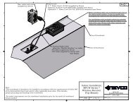
Your <strong>Message</strong> <strong>Center</strong> was designed so that it can be mounted in a variety of ways. Please<br />
examine the installation drawings to determine the best mounting method for your location.<br />
Access to all internal components is through the front, accessibility to the rear of the cabinet is<br />
NOT necessary. The standard mounting brackets are shipped on the <strong>Message</strong> <strong>Center</strong> in a<br />
“retracted” position and must be unbolted and rotated 180°, then reattached with the same bolts<br />
before starting the installation.<br />
Note: Please secure<br />
with two (2) fasteners at<br />
each mounting bracket<br />
location.<br />
Shipping Position<br />
Mounting Position<br />
Wall Mount<br />
135-0144 Page 1
Additional Suggested Mounting Methods<br />
Flush Mount<br />
Tubing Mount<br />
Note: Please see installation drawings for more details and options.<br />
135-0144 Page 2
3. <strong>Message</strong> <strong>Center</strong> Connections<br />
Each message center, whether it is made up of two cabinets end to end, or two cabinets back to back<br />
(double sided), or a single cabinet, requires that power and signal be supplied to each cabinet by the<br />
installer. All internal connections have been completed and tested at the factory.<br />
Both power and data should enter each message center cabinet at its lower left corner as viewed from<br />
the front. An access panel is provided for these connections. The “signal in”<br />
conduit attaches to the panel and a junction box is mounted on the panel for<br />
power connections. Similar access panels are installed on the back and<br />
bottom of the cabinet. All three panels are interchangeable so that the one<br />
with the junction box can be located in the most favorable position. The panel<br />
with the junction box can be moved to either of the other locations without<br />
disconnecting any cables inside the message center.<br />
Be sure to reattach all panels so as to maintain a weather tight seal.<br />
The optional temperature and light sensors should be mounted near this location and need to be<br />
connected to a cable inside the message center behind the access panel.<br />
At the lower right corner of the message center as viewed from the front is a<br />
similar arrangement for the “signal out” if needed. Used for side 2 of a two sided<br />
message center, and message centers made up of two cabinets mounted end to end.<br />
Note: Please see installation drawings for more details.<br />
135-0144 Page 3
Electrical Connections<br />
Refer to installation prints for illustration of electrical<br />
connections.<br />
Power Service<br />
This sign is intended to be installed in<br />
accordance with the requirements of Article 600<br />
of the National Electrical Code and/or other<br />
applicable local codes. This includes proper<br />
grounding and bonding of the sign.<br />
Consult table 1 for power requirements for your message<br />
center model. Provide for a 30% safety factor to guard<br />
against tripping of the circuit breaker under low line<br />
conditions.<br />
*Denoted values require 2 separate 20A breakers.<br />
Be sure to include any lighted signs, and account for<br />
double sided displays when sizing the supply wiring<br />
necessary to support the circuit load.<br />
A disconnect switch should be lockable or within sight of<br />
the sign per NEC article 600.<br />
Ethernet Cables<br />
In a wired configuration, connect from the PC to the<br />
controller with a crossover connection.<br />
If rigid EMT is used, use ¾” rain-tight conduit fittings to<br />
avoid cutting the ends off included pre-made cables.<br />
WARNING! Take care not to reverse the connections on<br />
the POE adapter as this will damage the controller. Refer<br />
to installation print and color coding for details.<br />
The diagrams below show Ethernet connections:<br />
Ethernet Straight through cable<br />
Ethernet Crossover cable<br />
20mm<br />
Color<br />
16mm<br />
(Amber<br />
/<br />
Red)<br />
32mm<br />
(Amber<br />
/<br />
Red)<br />
Cabinet<br />
Dimensions<br />
Current @<br />
120VAC<br />
Current @<br />
240VAC<br />
3x8 8.8 4.4<br />
3x10 11.3 5.7<br />
3x12 13.8 6.9<br />
4x8 12.3 6.2<br />
4x10 15.8 7.9<br />
4x12 Left 8.8 4.4<br />
4x12 Right 10.5 5.3<br />
4x16 Left 12.3 6.2<br />
4x16 Right 14.0 7.0<br />
1x6 1.1 0.6<br />
1x8 1.6 0.8<br />
2x6 2.2 0.9<br />
2x8 3.2 1.6<br />
3x6 3.2 1.6<br />
3x8 4.9 2.4<br />
3x10 5.9 3.0<br />
3x12 7.0 3.5<br />
4x8 6.5 3.2<br />
4x10 7.9 4.0<br />
4x12L 5.0 2.5<br />
4x12R 4.3 2.2<br />
4x16 Left 5.8 2.9<br />
4x16 Right 7.2 3.6<br />
2x8 3.2 1.6<br />
2x10 3.9 1.9<br />
2x12 4.9 2.5<br />
3x8 4.9 2.4<br />
3x10 5.9 3.0<br />
3x12 7.6 3.8<br />
3x16L 4.2 2.1<br />
3x16R 5.3 2.6<br />
4x8 6.5 3.2<br />
4x10 7.9 4.0<br />
4x12L 5.0 2.5<br />
4x12R 5.0 2.5<br />
4x16 Left 5.8 2.9<br />
4x16 Right 7.2 3.6<br />
PC<br />
POE<br />
Wireless<br />
AP<br />
2.4Ghz<br />
Wireless<br />
Wireless<br />
Bridge<br />
POE<br />
Sign Sign Side 2<br />
Rain-tight Box<br />
Figure 1 – Wireless Configuration<br />
T<br />
R<br />
if double sided<br />
PC<br />
Less than 325’<br />
Figure 2 – Wired Configuration Ethernet<br />
Sign<br />
T<br />
R<br />
Sign Side 2<br />
if double sided<br />
PC<br />
Media Converter<br />
Media Converter<br />
Sign<br />
T<br />
R<br />
Sign Side 2<br />
Fiber 325’ – 1.2 Miles<br />
Rain-tight Box<br />
Figure 3 – Wired Configuration Fiber Optic<br />
if double sided<br />
135-0144 Page 4
4. Software Setup<br />
The message center can be connected to a dedicated computer for setting up new messages, or integrated as part<br />
of an existing computer network. The system is shipped in the first case as described in “Not connected to<br />
existing Network”.<br />
Computer is Not connected to existing Network<br />
The message center controller and wireless equipment (optional) are pre-configured to a default network<br />
configuration. The IP address of the controller is set to 192.168.0.210. Wireless Bridge and AP are<br />
192.168.0.211 and 192.168.0.212 respectively.<br />
When the software is installed, the default projects are configured to talk to the default controller IP address.<br />
Follow these steps to set the controlling PC’s IP address to one that can communicate with the message<br />
center.<br />
1. Click the start button and select Control Panel. Double click Network Connections. Double click your<br />
network card or “Lan Connection”. On Win XP select properties. You will see the window on the left.<br />
Select Internet Protocol (TCP/IP) and click Properties. You will see the window on the right.<br />
2. Click the Radio Button “Use the following IP address” and enter 192.168.0.10 and the subnet mask<br />
255.255.255.0 and click ok on each window. You may be prompted to insert your Win98/2000 CD.<br />
3. When you open <strong>Nevco</strong> Composer, the button in the lower right hand corner of the screen should say<br />
“Update <strong>Message</strong> <strong>Center</strong>” showing that you are connected. (Be sure the license key is in the USB port<br />
and the LED is on)<br />
4. Consult the <strong>Nevco</strong> Composer user’s manual for troubleshooting.<br />
<br />
If you are using a laptop, make sure to turn off the wireless LAN in the laptop (if present). This can be done<br />
on most laptops by pressing a button in the area above the keyboard that looks like an antenna.<br />
135-0144 Page 5
Computer is Connected to an existing Network<br />
The message center controller and wireless equipment (optional) are pre-configured to a default network<br />
configuration. The IP address of the controller is set to 192.168.0.210. Wireless Bridge and AP are<br />
192.168.0.211 and 192.168.0.212 respectively.<br />
The steps to change the IP address on each of the devices are explained in detail in the user’s manuals for<br />
each device. Consult these manuals for more information. The wireless devices support DHCP, but the<br />
message center’s IP address must be static. To integrate the equipment into your existing network, in this<br />
order you must change the IP address on a computer, use that computer to change the message center IP<br />
address, change the outdoor bridge IP address, and then change the Access Point IP address. Follow these<br />
steps:<br />
1. Connect the access point to the LAN with a straight through Ethernet cable. The unit is shipped with a<br />
crossover cable for connecting directly to a PC.<br />
2. Change a PC on the network’s IP address as instructed in “Not connected to an existing Network”<br />
above.<br />
3. Change the <strong>Message</strong> <strong>Center</strong>’s IP address by following these steps.<br />
a. Install <strong>Nevco</strong> Composer on the Computer. Be sure to plug the license key into the USB port.<br />
b. Enter “Password” as instructed in the manual. As long as the password remains “Password” you<br />
will be prompted to change it each time the program is loaded.<br />
c. Go to <strong>Message</strong> <strong>Center</strong>=>Configure Password and <strong>Message</strong> <strong>Center</strong><br />
d. Enter your current password and click connect on the right hand side of the window.<br />
e. Enter the new IP address and subnet mask and click Update.<br />
4. Change the Outdoor wireless client’s IP address by following these steps.<br />
a. Open internet explorer and in the Address Bar type 192.168.0.211<br />
b. Refer to the sticker in your user’s manual for the username and password.<br />
c. A web page called Wireless Client Bridge will come up. Click on “TCP/IP Settings” and select<br />
“LAN Interface”.<br />
d. Change the network settings as necessary to fit your network topology and click “Apply<br />
Changes”.<br />
e. You may also want to change the wireless settings to suit your own security needs. Be sure to<br />
change the Access Point to match in the next section.<br />
5. Change the Access Point’s IP address by following these steps.<br />
a. Open internet explorer and in the Address Bar type 192.168.0.212<br />
b. Refer to the sticker in your user’s manual for the username and password.<br />
c. A web page called Wireless LAN Access Point will come up.<br />
d. Follow the same steps as 4, steps c - e. Make sure any security settings changed on the Client<br />
Bridge match settings on the Access point.<br />
6. You may now change your PC’s IP address back to its original configuration. Test the new<br />
configuration by opening <strong>Nevco</strong> Composer, going to Project=>Configure, enter the new IP address of<br />
the message center and click “OK”. The status at the bottom of the screen should now be “Display<br />
Connection = Ethernet”.<br />
135-0144 Page 6
INSTALLER’S TROUBLESHOOTING GUIDE<br />
The figure below labels the connections made by the installer from A – K. The chart below lists the problem that<br />
can be identified should each connection be faulty. Should a problem arise on any one component, consult the<br />
trouble shooting guide specific to that device.<br />
.Note: All connections inside the <strong>Message</strong> <strong>Center</strong> have been made at the NEVCO Factory. Each <strong>Message</strong><br />
<strong>Center</strong> requires Signal from the controlling PC. Each <strong>Message</strong> <strong>Center</strong> also requires Power (see Table 1).<br />
Note: For double sided and/or double cabinet message centers. The input signal for subsequent cabinets comes<br />
from the output of the previous cabinet. A separate power circuit is required for each cabinet.<br />
MESSAGE CENTER<br />
A<br />
J<br />
H<br />
G<br />
F<br />
D<br />
Temperature & Light<br />
Sensors<br />
C<br />
PC<br />
POE<br />
J<br />
Power<br />
Wireless<br />
AP<br />
2.4Ghz<br />
Wireless<br />
Wireless<br />
Bridge<br />
POE<br />
E<br />
Power<br />
Ethernet In<br />
B<br />
Power In<br />
K<br />
Ethernet Out<br />
To side 2<br />
(if applicable)<br />
Rain-tight Box<br />
If Outdoors<br />
135-0144 Page 7
Situation Symptom Connection Solution<br />
The message<br />
<strong>Center</strong> is not<br />
displaying a<br />
message<br />
I cannot<br />
communicate<br />
with the<br />
message<br />
center<br />
Part of<br />
message<br />
center<br />
appears<br />
“dead”<br />
The fans on ALL power supplies are<br />
running<br />
The fans on ALL power supplies are not<br />
running<br />
On a double sided <strong>Message</strong> <strong>Center</strong>, One<br />
side is displaying the message, the other<br />
is not<br />
“DSP” LED on controller IS blinking,<br />
but the CASCAN card has no LED’s<br />
blinking rapidly (like DSP on the<br />
controller).<br />
No Red Power LED lit on Wireless<br />
Bridge POE.<br />
No Red Power LED lit on Wireless<br />
Access Point POE.<br />
LAN LED on Controller not ON solid<br />
LAN LED on PC Ethernet port not ON,<br />
or PC says “network unplugged”, “not<br />
connected”.<br />
User’s manual on CD with wireless<br />
equipment explains how to measure the<br />
wireless signal strength<br />
Only part of message center will light<br />
C,D<br />
B<br />
K,c<br />
D<br />
E<br />
J<br />
D<br />
F<br />
H<br />
I<br />
G<br />
Replace crossover cable<br />
In Composer, check the scheduling for the Project, then<br />
click the button to send the project to message center<br />
Check Power Switch on disconnect box inside message<br />
center<br />
Check connections in disconnect box (power hookup)<br />
Check branch circuit; was there a photocell on an existing<br />
sign install<br />
Ensure an Ethernet straight through cable has been used, is<br />
making a good connection at both ends.<br />
Ensure an Ethernet crossover cable has been used, is<br />
making a good connection at both ends.<br />
Check branch circuit and power at the receptacle. Adapter<br />
has LED indicator<br />
Check branch circuit and power at the receptacle. Adapter<br />
has LED indicator<br />
Ensure an Ethernet crossover cable has been used and is<br />
making a good connection at both ends<br />
Ensure an Ethernet straight through cable has been used and<br />
is making a good connection at both ends.<br />
Ensure an Ethernet straight through cable has been used and<br />
is making a good connection at both ends.<br />
Ensure an Ethernet crossover cable has been used and is<br />
making a good connection at both ends. Check to see that<br />
the network interface is enabled and follow the procedure in<br />
“Not connected to existing Network above.<br />
Reorient the wireless device’s antennas to eliminate<br />
obstructions between them<br />
In Composer, check the zone section to make sure the<br />
project is set to use the whole message center<br />
Temperature<br />
Sensor does<br />
Not installed A Install sensor in message center<br />
NOT work Not enabled Make sure the temperature sensor is enabled in Composer<br />
Light Sensor<br />
does NOT<br />
Not installed A Install sensor in message center<br />
work Not enabled Make sure the light sensor is set to auto in Composer<br />
If the problem persists please contact the <strong>Nevco</strong> Service Department.<br />
800-851-4040<br />
135-0144 Page 8
GLOSSARY<br />
ACCESS POINT (WIRELESS AP)<br />
A hardware device that allows wireless<br />
communication devices to connect to a<br />
network.<br />
Can also be configured as a<br />
WIRELESS BRIDGE<br />
A hardware device used to connect two or<br />
more network segments.<br />
CASCAN card<br />
Distributes the data inside the <strong>Message</strong><br />
<strong>Center</strong>.<br />
CASCAN card<br />
135-0144 Page 9
DISPLAY Panel<br />
A group of pixels. Several Display Panels are combined to form the message center.<br />
DSP<br />
Digital Signal Processing.<br />
PIXEL<br />
A group of one or more LEDs.<br />
POE<br />
Power Over Ethernet.<br />
Used to inject power for use by<br />
A device connected to the<br />
Ethernet cable.<br />
POWER SUPPLY<br />
Converts the line voltage to 12 volts or 5 volts.<br />
POWER SWITCH<br />
Disconnects power to a portion of the message center components. Cabinet may contain more than one.<br />
RIBBON CABLE<br />
Flat 16 conductor cable used to carry the data from the CASCAN card to the display panels and from display panel to<br />
display panel.<br />
WIRELESS BRIDGE<br />
A hardware device used to connect two or more network segments. (See Access Point)<br />
135-0144 Page 10
X-6 (CONTROLLER)<br />
Stores, processes, and distributes the message center data to the CASCAN card(s).<br />
X-6 CONTROLLER<br />
X-6 CONTROLLER with power supply
<strong>Nevco</strong><br />
Outdoor LED Scoreboard<br />
<strong>Installation</strong> <strong>Manual</strong><br />
Retain this manual in your permanent file.<br />
7/06/2010 135-0209
<strong>Installation</strong> Instructions<br />
<strong>Installation</strong> consists of three steps, Unpacking the Equipment, Scoreboard mounting, and Electrical Connections.<br />
Be sure to read and understand all of the instructions before installing the equipment. Consult the “installer’s<br />
troubleshooting guide” following this section for verifications each step has been installed and is working correctly.<br />
1. Unpacking the Equipment<br />
<br />
<br />
Inspect the shipping container for damage. If any damage can be seen, contact the carrier immediately.<br />
Carefully remove all equipment from its packing carton. Do not pry against the scoreboard in any way.<br />
2. Scoreboard Mounting<br />
Note: For scoreboards that are shipped in more than one section, doors on the back of the scoreboard provide<br />
access to cables that must be connected and routed between sections during installation.<br />
<br />
<br />
Refer to installation prints for mounting method, mounting centers, power service location, and cable routings.<br />
A wide flanged steel support system recommended by <strong>Nevco</strong> on the installation print, can tolerate a nominal<br />
90-mph wind loading. This may not be adequate for some locales. <strong>Nevco</strong> strongly encourages you to check<br />
local codes before beginning the installation. You may wish to contact a local engineer, architect, or sign<br />
installer for assistance. Your <strong>Nevco</strong> Sales Representative may be able to assist you in finding professional<br />
installers who are familiar with this type of equipment.<br />
Front edge<br />
S Bracket<br />
<br />
<br />
<br />
<br />
<br />
Before mounting the supplied S brackets to the beams, measure the slot locations on the scoreboard.<br />
Manufacturing tolerances, temperatures and other variables may affect the actual slot location.<br />
Mount an S bracket to each beam where the bottom edge of the scoreboard will rest with two 5/8” bolts.<br />
After the bottom S brackets are secured, position the scoreboard by aligning the holes in the front edge of the S<br />
brackets with the 1-1/2-in. x 11/16-in. slots on the face of the scoreboard.<br />
Install the top S brackets securely against the top of the scoreboard, aligning the S bracket holes with the<br />
scoreboard slots.<br />
When all S brackets are in place, insert a 5/8-in. bolt through the front of the S brackets, scoreboard, and wide<br />
flange beam. Secure the bolt with a flat washer and locking nut.<br />
Note: A self-locking nut must be used to prevent loosening. Do not over-tighten this bolt.<br />
Always use good mechanical practices when mounting the scoreboard:<br />
The distance between the mounting posts must be maintained within a tolerance of ±0.5 in. so that the mounting<br />
devices can be properly secured.<br />
<br />
Use only plated fastening devices to prevent rust or corrosion.<br />
135-0209 Page 1
Assembling Sectional Scoreboard<br />
For scoreboards with multiple bottom sections, slide the pieces together aligning the pre-drilled<br />
holes. Fasten sections with the sheet metal screws provided.<br />
Note: The screws are shipped in the accessory package with the S brackets.<br />
Use silicon caulk and join vertical seams with screws provided. Position the top section(s) in place<br />
above the bottom section(s). Fasten sections with the sheet metal screws provided.<br />
Locate and remove the access doors on the back of the scoreboard. Make sure all cables are<br />
connected as necessary at cabinet joints.<br />
Check all electronic devices for loose connectors. See <strong>Installation</strong> Print for detail.<br />
J-TYPE MOUNTING BRACKET<br />
Use the included J-type mounting brackets to secure the<br />
scoreboard to the posts at the section joints.<br />
Note: These mounting brackets should be used on<br />
the section joints, even if you do not use the<br />
posts that <strong>Nevco</strong> specifies.<br />
Number of<br />
Columns<br />
1 Post PSD-A, DGT-5A, 9505-A, PCD<br />
Scoreboard Models<br />
2 Post 1500, 1510, 1520, 1525, 1540, 1550, 3502, 3550, 3555, 9560, 1508,<br />
1515, 1530, 1535, 3500, 3514, 3525, 3534, 5525, 7504, 7524, 9550<br />
3 Post 1506, 3515, 3520, 7520, 7530, 7505, 7525<br />
4 Post 3504, 1503, 3516, 7516<br />
Rain Tight Enclosure Box<br />
For scoreboards that will be operated wirelessly, a rain tight enclosure box must be mounted on one of the posts<br />
holding the scoreboard. This rain tight box houses the wireless receiver and must be mounted on the same side of<br />
the post as the scoreboard (Clear line-of-sight, facing the operator’s control) and must have power supplied to it<br />
(See drawing).<br />
135-0209 Page 2
3. Electrical Connections<br />
<br />
<br />
Refer to installation prints for illustration of electrical connections.<br />
Power Service<br />
This sign is intended to be installed in<br />
accordance with the requirements of<br />
Article 600 of the National Electrical<br />
Code and/or other applicable local<br />
codes. This includes proper grounding<br />
and bonding of the sign.<br />
Consult table 1 for Full Load power<br />
requirements for your scoreboard model. Provide<br />
for a 30% safety factor when sizing wire and<br />
selecting breakers to guard against tripping of the<br />
circuit breaker under low line conditions.<br />
Be sure to include any lighted signs, and<br />
message centers when sizing the supply wiring<br />
necessary to support the circuit load.<br />
A disconnect switch should be lockable or within<br />
sight of the sign per NEC article 600.<br />
Two holes in the back of the scoreboard provide<br />
an entrance point for the power and the coax<br />
signal cable. These holes are plugged at the<br />
factory and you may make your own entry points<br />
if desired; take care not to drill into or damage<br />
any of the internal components of the<br />
scoreboard. A removable panel on the front of<br />
the scoreboard opposite the holes in the back<br />
allows access to an Electrical Enclosure box.<br />
Remove the front of the Electrical Enclosure box<br />
to gain access to the power splice box where the<br />
scoreboard power connections are made. The<br />
coax signal cable terminates on a BNC connector<br />
on the bottom of the Electrical Enclosure box.<br />
The rain tight enclosure box, mounted on one of<br />
the scoreboard posts, houses the receiver in a<br />
wireless scoreboard system and will need power<br />
to it. The rain tight receiver box must be facing<br />
the field, providing clear line-of-sight from the<br />
wireless control. See drawings for more details.<br />
<br />
Electronic Team Names, on the large 3516 and<br />
7516 require separate power to be run to them.<br />
Power must be run to Home and Guest. Power<br />
entrance labels on the back of the scoreboard identify the default locations.<br />
Current Current With ETN With ETN<br />
Model # @ 120V @ 240V @ 120V @ 240V<br />
1500 0.7 A 0.4 A 1.2 A 0.6 A<br />
1503 5.1 A 2.6 A 5.8 A 2.9 A<br />
1506 3.1 A 1.6 A 3.8 A 1.9 A<br />
1508 2.0 A 1.0 A 2.5 A 1.3 A<br />
1510 0.7 A 0.4 A N/A N/A<br />
1515 1.3 A 0.6 A 1.8 A 0.9 A<br />
1520 0.9 A 0.4 A N/A N/A<br />
1525 1.0 A 0.5 A N/A N/A<br />
1530 2.2 A 1.1 A 2.9 A 1.5 A<br />
1535 1.2 A 0.6 A 1.7 A 0.9 A<br />
1540 1.5 A 0.8 A 2.2 A 1.1 A<br />
1550 0.4 A 0.2 A N/A N/A<br />
3500 2.5 A 1.2 A 3.2 A 1.6 A<br />
3502 1.3 A 0.7 A 1.8 A 0.9 A<br />
3504 3.3 A 1.6 A 4.0 A 2.0 A<br />
3514 2.8 A 1.4 A 3.5 A 1.8 A<br />
3515 2.8 A 1.4 A 3.5 A 1.8 A<br />
3516 4.7 A 2.3 A 7.1 A 3.6 A<br />
3520 3.3 A 1.6 A 4.0 A 2.0 A<br />
3525 2.7 A 1.4 A 3.4 A 1.7 A<br />
3534 3.0 A 1.5 A 3.7 A 1.9 A<br />
3550 0.8 A 0.4 A N/A N/A<br />
3555 1.8 A 0.9 A 2.3 A 1.2 A<br />
5525 2.8 A 1.4 A N/A N/A<br />
7504 3.4 A 1.7 A 4.1 A 2.1 A<br />
7505 4.3 A 2.2 A 5.0 A 2.5 A<br />
7516 5.0 A 2.5 A 7.4 A 3.7 A<br />
7520 3.4 A 1.7 A 4.1 A 2.1 A<br />
7524 3.0 A 1.5 A 3.7 A 1.9 A<br />
7525 4.0 A 2.0 A 4.7 A 2.4 A<br />
7530 3.3 A 1.6 A 4.0 A 2.0 A<br />
9505-A 0.4 A 0.2 A N/A N/A<br />
9550 2.9 A 1.5 A N/A N/A<br />
9560 1.6 A 0.8 A N/A N/A<br />
DGT-5A 0.6 A 0.3 A N/A N/A<br />
PSD-A 0.6 A 0.3 A N/A N/A<br />
PCD 0.3 A 0.2 A N/A N/A<br />
Table 1<br />
135-0209 Page 3
2-Wire Coax Cable (RG58/U)<br />
All 2-WIRE cable ordered from <strong>Nevco</strong> is direct burial type. It has a minimum dielectric strength of 300V, and<br />
conforms to UL standard 1365.<br />
If the wiring is buried above the freeze line, bury the cable with sand to provide drainage and prevent damage from<br />
shifting soil.<br />
Installing Cable Connectors<br />
The 2-WIRE cable that comes with your scoreboard does not have connectors attached.<br />
1<br />
4 "<br />
9<br />
16 "<br />
Insulating boot<br />
1<br />
32 "<br />
To install connectors on each end of the cable:<br />
<br />
<br />
<br />
<br />
<br />
<br />
Slide the insulating boot onto the cable and trim the cable as shown.<br />
Twist the outer braid in a clockwise direction so that at least 1/32 in. of the inner dielectric is bared and the<br />
braid is left flat. Be sure no strands of the outer braid are touching the center conductor.<br />
Insert the center conductor into the back of the connector, feeding it into the guide hole.<br />
Push the cable as far as possible into the connector.<br />
Screw the connector onto the cable in a clockwise direction until the connector stops turning.<br />
Slip the insulating boot over the back of the connector.<br />
135-0209 Page 4
WIRED INSTALLER’S TROUBLESHOOTING GUIDE<br />
The figure to the right<br />
labels the connections<br />
made by the installer<br />
from A &B as well as<br />
other useful internal<br />
connections C - J. The<br />
chart below lists the<br />
problem that can be<br />
identified should each<br />
connection be faulty.<br />
Check the control and<br />
service manual for more<br />
detailed information.<br />
Branch<br />
Circuit<br />
Control<br />
3<br />
A<br />
2 (coax)<br />
B<br />
Power Supply<br />
Power Supply<br />
Power<br />
Supply<br />
C 4<br />
D 4<br />
E 4<br />
1<br />
2<br />
3<br />
Signal<br />
In<br />
OCM<br />
Horn1<br />
1<br />
2<br />
3<br />
2<br />
F<br />
6<br />
G<br />
Horn<br />
(Future)<br />
Master<br />
Digit<br />
2<br />
I<br />
14<br />
H<br />
6<br />
J<br />
Slave<br />
Digit<br />
Bullseye or<br />
other accessory<br />
To Next Digit<br />
OR ETN<br />
Situation Symptom Connection Solution<br />
Check branch circuit breaker, connections, and disconnect switch external to<br />
scoreboard<br />
The Scoreboard<br />
has no digits<br />
illuminated<br />
Some digits not<br />
illuminated, or<br />
non-working<br />
accessory<br />
The fans on ALL the power supplies are not running<br />
OCM LED ON solid<br />
OCM LED is flashing rapidly<br />
OCM LED is completely OFF<br />
A<br />
B<br />
C or D<br />
G<br />
E<br />
Check connections in disconnect box (power hookup)<br />
Check Power Switch on disconnect box inside scoreboard<br />
Replace Power supply<br />
Check Coax connections. Plug control directly into OCM to eliminate buried<br />
coax cable. If that works, the cable run or terminations are bad. Try the 301<br />
Model code, see control users manual on testing.<br />
Holding the Button on the OCM down for 4 seconds will display a test pattern<br />
on the scoreboard digits further confirming that the signal connection is bad<br />
The power cable plugged into port 3 powers the OCM, but connections to power<br />
supplies on plug 1 & 2 power the digits/ETN’s powered by 1 & 2 outputs<br />
Check connections on OCM outputs 1, 2, & 3 as well as first master digits<br />
OCM board has no power. Check connection E, power supply feeding E, and<br />
connections to the power supply E.<br />
Only one digit H Check 14-pin connection on Driver card and 2-pin on segments<br />
Horn, colon, decimal, possession indicator, etc. I Check 2-pin connection on Driver card and on accessory<br />
More than one Digit, starts at one point in cabling J Check 6-pin connection from working driver card to next digit driver card<br />
135-0209 Page 5
Wireless<br />
Troubleshooting<br />
Guide<br />
The figure to the right labels<br />
the connections potentially<br />
made by the installer (A – E)<br />
and other internal connections<br />
(F – M) useful to<br />
troubleshooting. The chart<br />
below lists the problem that<br />
can be identified should each<br />
connection be faulty. Check<br />
the control and service manual<br />
for more detailed information.<br />
C<br />
o<br />
n<br />
t<br />
r<br />
o<br />
l<br />
Branch<br />
Circuit<br />
3 A<br />
Power<br />
Adapter<br />
0<br />
900Mhz<br />
D<br />
2<br />
B<br />
3<br />
C<br />
Receiver<br />
Power Supply<br />
Power Supply<br />
Power<br />
Supply<br />
2 (coax)<br />
E<br />
F 4<br />
G 4<br />
H 4<br />
1<br />
2<br />
3<br />
Signal<br />
In<br />
OCM<br />
Horn1<br />
1<br />
2<br />
3<br />
6<br />
J<br />
Horn<br />
(Future)<br />
Situation Symptom Connection Solution<br />
The fans on the ALL power supplies are not running<br />
C<br />
2<br />
I<br />
Master<br />
Digit<br />
2<br />
L<br />
14<br />
K<br />
6<br />
M<br />
Slave<br />
Digit<br />
Check branch circuit breaker, connections, and disconnect switch external to scoreboard<br />
Check connections in disconnect box (power hookup)<br />
Check Power Switch on disconnect box inside scoreboard<br />
Replace Power supply<br />
Bullseye or<br />
other accessory<br />
The Scoreboard<br />
has no digits<br />
illuminated<br />
Some digits not<br />
illuminated, or<br />
non-working<br />
accessory<br />
Receiver has No LEDs illuminated during first 5 seconds after<br />
power up<br />
Receiver LED Not ON solid<br />
OCM LED ON solid<br />
OCM LED is flashing rapidly<br />
OCM LED is completely OFF<br />
A<br />
B<br />
D<br />
E<br />
F or G<br />
G<br />
H<br />
Check branch circuit breaker, connections, duplex receptacle, and disconnect switch external to scoreboard<br />
If the duplex receptacle has power, but the adapter LED is OFF, replace adapter<br />
Ensure DC plug is fully seated in receiver DC jack and making good connection<br />
Replace Receiver<br />
Follow control troubleshooting procedures, wrong wireless group, etc.<br />
Receiver should be in clear line of sight from control.<br />
Check Coax connections. Plug control directly into OCM to eliminate buried coax cable. If that works, the cable<br />
run or terminations are bad. Try the 301 Model code, see control users manual on testing.<br />
Holding the Button on the OCM down for 4 seconds will display a test pattern on the scoreboard digits further<br />
confirming that the signal connection is bad<br />
The power cable plugged into port 3 powers the OCM, but connections to power supplies on plug 1 & 2 power<br />
the digits/ETN’s powered by 1 & 2 outputs<br />
Check connections on OCM outputs 1, 2, & 3 as well as first master digits<br />
OCM board has no power. Check connection E, power supply feeding E, and connections to the power supply<br />
E.<br />
Only one digit K Check 14-pin connection on Driver card and 2-pin on segments<br />
Horn, colon, decimal, possession indicator, etc. L Check 2-pin connection on Driver card and on accessory<br />
More than one Digit, starts at one point in cabling M Check 6-pin connection from working driver card to next digit driver card<br />
135-0209 Page 6
NEVCO GUARANTEE<br />
To view or receive the most recent copy of the Guarantee, please visit our website,<br />
www.nevco.com or call 1-618-664-0360<br />
— IN USA — — IN CANADA —<br />
NEVCO, Inc.<br />
301 East Harris Avenue<br />
Greenville, IL 62246-2151 USA<br />
Telephone: 618-664-0360<br />
Fax: 618-664-0398<br />
TOLL-FREE 800-851-4040<br />
(From all 50 states and Puerto Rico)<br />
NEVCO, ULC<br />
107 Forestview Rd.<br />
Orillia, ON L3V 7C1 Canada<br />
Telephone: 703-325-4005<br />
Fax: 705-325-8891<br />
TOLL-FREE 800-461-8550<br />
Website: www.nevco.com<br />
Email: info@nevco.com<br />
NOTE: This equipment has been tested and found to comply with the limits for a Class A digital device, pursuant to part 15 of the FCC Rules. These limits are designed<br />
to provide reasonable protection against harmful interference when the equipment is operated in a commercial environment. This equipment generates, uses, and can<br />
radiate radio frequency energy and, if not installed and used in accordance with the instruction manual, may cause harmful interference to radio communications.<br />
Operation of this equipment in a residential area is likely to cause harmful interference in which case the user will be required to correct the interference at his own<br />
expense.<br />
This class A digital apparatus meets all requirements of the Canadian Interference- Causing Equipment Regulations.<br />
Cet appareil numerique de la classe A repecte toutes les exigences du Reglement sure le materiel brouller du Canada.<br />
135-0209<br />
Page 7