Technology review of constructed wetlands - Gtz - GIZ
Technology review of constructed wetlands - Gtz - GIZ
Technology review of constructed wetlands - Gtz - GIZ

You also want an ePaper? Increase the reach of your titles
YUMPU automatically turns print PDFs into web optimized ePapers that Google loves.
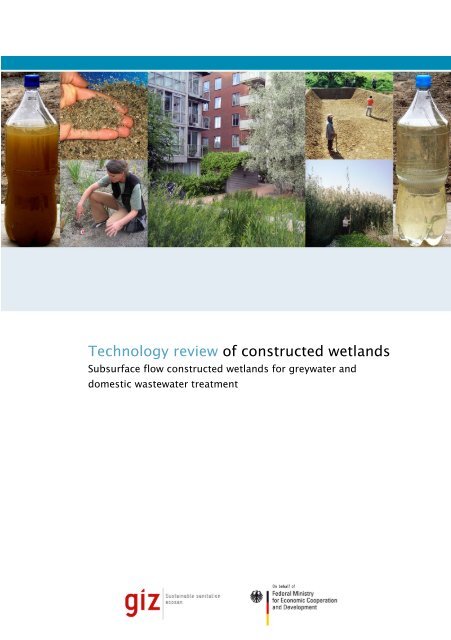
<strong>Technology</strong> <strong>review</strong> <strong>of</strong> <strong>constructed</strong> <strong>wetlands</strong>Subsurface flow <strong>constructed</strong> <strong>wetlands</strong> for greywater anddomestic wastewater treatment
Contents1 Summary ................................................................................................................................................................................. 82 Introduction .............................................................................................................................................................................. 82.1 Target audience ................................................................................................................................................................ 82.2 Scope <strong>of</strong> this document .................................................................................................................................................... 82.3 Definition and terminology ................................................................................................................................................ 92.4 Historical development ..................................................................................................................................................... 92.5 Classification <strong>of</strong> <strong>constructed</strong> <strong>wetlands</strong> .............................................................................................................................. 92.6 Range <strong>of</strong> applications ..................................................................................................................................................... 102.7 <strong>Technology</strong> selection ...................................................................................................................................................... 102.7.1 Space requirements as a selection criterion ......................................................................................................... 102.7.2 Comparison <strong>of</strong> subsurface flow CWs with high-rate aerobic treatment processes ................................................ 102.7.3 Comparison <strong>of</strong> subsurface flow CWs with ponds .................................................................................................. 102.7.4 Cost considerations .............................................................................................................................................. 112.8 Reuse aspects ................................................................................................................................................................ 112.8.1 Reuse for irrigation ................................................................................................................................................ 112.8.2 Hygiene aspects (pathogens) ............................................................................................................................... 112.8.3 Quantity aspects ................................................................................................................................................... 112.8.4 Colour aspects ...................................................................................................................................................... 123 Design criteria for subsurface flow CWs ................................................................................................................................ 123.1 Treatment principles ....................................................................................................................................................... 123.1.1 Overview <strong>of</strong> main processes ................................................................................................................................. 123.1.2 Pollutant removal ratios for greywater treatment ................................................................................................... 133.1.3 Nutrient removal .................................................................................................................................................... 133.1.4 Role <strong>of</strong> plants in subsurface flow CWs .................................................................................................................. 143.2 Basic design considerations ........................................................................................................................................... 143.2.1 Necessary conditions and basic setup .................................................................................................................. 143.2.2 Major components and design life ........................................................................................................................ 153.2.3 Design parameters ................................................................................................................................................ 153.2.4 Typical values for area requirements .................................................................................................................... 163.2.5 Design differences between CWs for domestic wastewater versus CWs for greywater ....................................... 163.3 Substrate used in subsurface flow CWs ......................................................................................................................... 163.4 Types <strong>of</strong> plants used ...................................................................................................................................................... 174 Pre-treatment <strong>of</strong> wastewater before subsurface flow CW treatment ...................................................................................... 184.1 Overview <strong>of</strong> processes ................................................................................................................................................... 184.2 Biogas emissions during pre-treatment .......................................................................................................................... 194.3 Grease trap .................................................................................................................................................................... 194.4 Septic tank ...................................................................................................................................................................... 194.5 Compost filter ................................................................................................................................................................. 204.6 Imh<strong>of</strong>f tank ...................................................................................................................................................................... 204.7 Baffled tank .................................................................................................................................................................... 214.8 UASB reactor ................................................................................................................................................................. 215 Design principles for subsurface flow CWs ............................................................................................................................ 215.1 Horizontal flow beds (HFBs)........................................................................................................................................... 225.2 Vertical flow beds (VFBs) ............................................................................................................................................... 235.2.1 Basic design recommendations ............................................................................................................................ 235.2.2 Soil clogging and soil aeration in VFBs ................................................................................................................. 245.3 The French System for combined primary and secondary treatment <strong>of</strong> raw wastewater ............................................... 245.4 Hybrid systems ............................................................................................................................................................... 264
5.5 Project examples ............................................................................................................................................................ 266 Operation and maintenance .................................................................................................................................................. 276.1 Operational tasks for HFBs and VFBs ............................................................................................................................ 276.2 Tasks for the operation <strong>of</strong> HFBs ..................................................................................................................................... 276.3 Tasks for the operation <strong>of</strong> VFBs ..................................................................................................................................... 286.4 Should wetland plants be harvested or not? ................................................................................................................... 286.5 Basic trouble-shooting .................................................................................................................................................... 297 References and further resources ......................................................................................................................................... 297.1 Documents cited ............................................................................................................................................................. 297.2 Further recommended reading ....................................................................................................................................... 317.2.1 Various publications on <strong>constructed</strong> <strong>wetlands</strong> ...................................................................................................... 317.2.2 Case Studies <strong>of</strong> the Sustainable Sanitation Alliance (SuSanA) ............................................................................ 327.3 Photos and technical drawings ....................................................................................................................................... 328 Appendix ................................................................................................................................................................................ 328.1 Appendix 1: Characteristics <strong>of</strong> domestic wastewater and greywater .............................................................................. 328.1.1 Domestic wastewater ............................................................................................................................................ 328.1.2 Greywater ............................................................................................................................................................. 338.2 Appendix 2: Further details on pathogens and their removal in <strong>constructed</strong> <strong>wetlands</strong> ................................................... 348.3 Appendix 3: Recommended grain size distribution <strong>of</strong> sand in subsurface flow CWs ...................................................... 35List <strong>of</strong> Tables:Table 1. Overview <strong>of</strong> pollutant removal processes in subsurface flow CWs. ............................................................................. 12Table 2. Removal ratios (in %) <strong>of</strong> HFBs and VFBs (subsurface flow CWs) for greywater treatment. The values aresimilar for domestic wastewater treatment. .................................................................................................................. 13Table 3. Approximate design values to estimate the area requirement for subsurface flow CWs in different climateconditions for domestic wastewater (after pre-treatment). ........................................................................................... 16Table 4. Overview <strong>of</strong> some possible plants which can be used in subsurface flow CWs in warm climates. All plantsshown below are macrophyte plants, except vetiver which is a perennial grass. Many other plants arepossible, see for example Brisson and Chazarenc (2009)........................................................................................... 17Table 5. Overview <strong>of</strong> available pre-treatment processes and their suitability for different wastewater types: GW standsfor greywater, WW stands for wastewater (X means: can be used). ............................................................................ 18Table 6. Example area requirements for VFBs (see SuSanA case studies for details). ............................................................ 26Table 7. Example <strong>of</strong> the load calculation <strong>of</strong> greywater and blackwater streams and the resulting area occupation <strong>of</strong>the two CWs for a school in Lima, Peru (design basis was 70 p.e.). Italic text in brackets provides thereduction rates. ............................................................................................................................................................ 27Table 8. Typical unit loading factors in raw wastewater for four countries. ................................................................................ 32Table 9. Typical microorganism and pathogen concentrations found in raw wastewater. ......................................................... 34Table 10. Log unit reduction <strong>of</strong> pathogens by selected treatment processes (from WHO (2006), volume 2). ............................. 34List <strong>of</strong> Figures:Figure 1. Classification <strong>of</strong> <strong>constructed</strong> <strong>wetlands</strong> (modified from Vymazal and Kroepfelová, 2008). The dashed ellipsesignifies the focus <strong>of</strong> this document. HFB and VFB are abbreviations for horizontal and vertical flow bed,respectively. Hybrid systems are also possible. “Emergent plants” are a type <strong>of</strong> macrophyte where the leavesare above the water level. .............................................................................................................................................. 9Figure 2. Urban decentralised greywater treatment with a subsurface flow CW in Klosterenga in Oslo, Norway (photoby L. Ulrich, 2008). ....................................................................................................................................................... 10Figure 3. The treated effluent (left) <strong>of</strong> the vertical flow <strong>constructed</strong> wetland in Haran Al-Awamied, Syria, is collected inthis storage tank (right) before its reuse for irrigation in agriculture (photos by E. von Muench, 2009; projectsupported by <strong>GIZ</strong>). ....................................................................................................................................................... 11Figure 4. Wastewater samples before and after treatment in a VFB. Left photo: pre-treated greywater (left bottle) andeffluent <strong>of</strong> the CW which is reused for irrigation <strong>of</strong> crops (right bottle). Right photo: pre-treated blackwater(left bottle) and effluent <strong>of</strong> the CW which has the typical brownish colouration caused by humic acid (rightbottle) (photos by: H. H<strong>of</strong>fmann, 2008). ....................................................................................................................... 125
Figure 5. Root and rhizome system <strong>of</strong> reed (Phragmites australis) (left picture) and arundo donax (right picture)(photos by M. Blumberg, 1995). ................................................................................................................................... 14Figure 6. VFB under construction, during influent pumping with greywater to test for uniform distribution in Lima, Peru.Note the small holes in distribution pipes. The entire surface is used as an inlet area, and the pipes are latercovered with gravel after completing the testing (photo by H. H<strong>of</strong>fmann, 2008). ......................................................... 15Figure 7. VFB under construction in Bayawan City, Philippines; the wetland will treat wastewater from a landfill (photoby J. Boorsma, 2009; project supported by <strong>GIZ</strong>). ........................................................................................................ 15Figure 8. Example <strong>of</strong> filter material used for VFBs for municipal wastewater treatment in Brazil: coarse sand from river,containing neither loam nor silt (photo by C. Platzer, 2008). ........................................................................................ 16Figure 9. Left: VFB during construction in Palhoça, Santa Catarina, Brazil; drain pipes situated on top <strong>of</strong> the PE linerare being covered with gravel. Right: VFB in Lima, Peru during filling with sand (photos by H. H<strong>of</strong>fmann,2007). ........................................................................................................................................................................... 17Figure 10. Reed after two years <strong>of</strong> growth in a VFB treating domestic wastewater at Haran Al-Awamied nearDamascus, Syria (photo by E. von Muench, 2009; project supported by <strong>GIZ</strong>). ............................................................ 18Figure 11. Papyrus after six months <strong>of</strong> growth in a VFB treating domestic wastewater in Florianópolis, Brazil (photo byC. Platzer, 2008). ......................................................................................................................................................... 18Figure 12. Simsen (Scirpus sp.) in a VFB treating domestic wastewater in the Olympic Forest Park in Beijing, China(photo by J. Germer, 2008). ......................................................................................................................................... 18Figure 13: Pumping <strong>of</strong> settled sludge from pre-treatment unit <strong>of</strong> subsurface flow CW in Tirana, Albania. The removedsludge will be taken to a local wastewater treatment plant by tanker (project supported by <strong>GIZ</strong>, photo by J.Nowak, 2010) ............................................................................................................................................................... 19Figure 14. Left: Grease trap schematic. Right: Opened grease trap used for effluent <strong>of</strong> a kitchen sink <strong>of</strong> a household inLima, Peru before wetland treatment. The inner bucket can be taken out to remove the grease (sources: H.H<strong>of</strong>fmann, 2010). ......................................................................................................................................................... 19Figure 15. Left: Septic tank schematic. Right: 3-chamber septic tank under construction at a house with 15 habitants inLima, Peru (sources: H. H<strong>of</strong>fmann, 2009). ................................................................................................................... 20Figure 16. Left: Imh<strong>of</strong>f tank schematic with three compartments. Right: Imh<strong>of</strong>f tank under construction in a rural area <strong>of</strong>Peru (sources: H. H<strong>of</strong>fmann, 2008). ............................................................................................................................ 21Figure 17. Schematic <strong>of</strong> baffled tank with six compartments (source: Gutterer et al., 2009). ....................................................... 21Figure 18. Schematic cross-section <strong>of</strong> a HFB (source: Morel and Diener, 2006). ........................................................................ 22Figure 19. Schematic cross-section <strong>of</strong> a HFB showing pre-treatment with a septic tank on the left (source: Fehr, 2003). ........... 22Figure 20. Inflow zone with stones in a HFB near Leiria, Portugal (photo by J. Vymazal, 2003). ................................................. 22Figure 21. Left: Side view <strong>of</strong> the liquid level in a HFB showing inlet dam to control clogging and prevent surface run-<strong>of</strong>f<strong>of</strong> the wastewater. Left vertical arrow is influent and right vertical arrow is effluent. Right: Top view <strong>of</strong> correctgeometry <strong>of</strong> larger HFBs where filter length (see vertical arrows) is 5-8 m, and bed width (see horizontalarrows) is maximum <strong>of</strong> 30 m (source: Platzer, 2000). .................................................................................................. 23Figure 22. Schematic cross-section <strong>of</strong> a VFB (source: Morel and Diener, 2006). The middle layer <strong>of</strong> coarse sandtypically has a height <strong>of</strong> 50 cm, the top gravel layer a height <strong>of</strong> 10 cm. ....................................................................... 24Figure 23. Schematic cross-section <strong>of</strong> a VFB showing pre-treatment with a septic tank on the left (source: Fehr, 2003). ........... 24Figure 24. French System, from left to right: three VFBs (filters) for pre-treatment and two VFBs for secondarytreatment in Albondón, Spain, with 800 inhabitants. The plant needs no electricity supply as it is built on aslope (photo by T. Burkard, 2005)................................................................................................................................ 25Figure 25. Pre-treatment <strong>of</strong> raw wastewater in the first stage (a VFB) <strong>of</strong> the French System (source: Molle et al., 2005).Wastewater flows out <strong>of</strong> the end <strong>of</strong> the distribution pipes (without small holes along the pipe length). ....................... 25Figure 26. Distribution pipes for raw wastewater in first stage (VFB) in French System in Albondón, Spain (photo by T.Burkard, 2007). ............................................................................................................................................................ 25Figure 27. Subsurface flow CW in Bayawan city, Philippines. The path in the middle separates the VFB and the HFB(photo by J. Boorsma, 2009; project supported by <strong>GIZ</strong>). ............................................................................................. 26Figure 28. Left: Malfunctioning grease trap with too much sludge accumulation. Right: the sludge from the grease trapobstructs the infiltration area <strong>of</strong> the CW which has become black because there is no oxygen transportanymore and it has become clogged (photo by H. H<strong>of</strong>fmann, 2009). .......................................................................... 27Figure 29. Left: cleaning the wastewater distribution pipes by opening and closing valves and caps during the pumpingphase (medium sized papyrus umbrella sedge plants just after re-planting). Right: opened cap on a blockeddistribution pipe (photos <strong>of</strong> VFB for blackwater treatment at school in Lima, Peru by H. H<strong>of</strong>fmann, 2009) ................. 28Figure 30. Constructed wetland in Dubai for wastewater treatment where the reed reached a height <strong>of</strong> 6 m (photo by W.Sievert, 2007). ............................................................................................................................................................. 29Figure 31. Cyperus papyrus after 12 months <strong>of</strong> growth in a VFB: Growth has occurred on the surface but withoutenough vertical roots. The plants may fall over and do not contribute to the treatment process anymore. Theyneed to be removed and replanted (photo by H. H<strong>of</strong>fmann, 2008). ............................................................................. 29Figure 32. Recommended grain size distribution <strong>of</strong> sand in subsurface flow CWs (Platzer, 1998). The sieving curve <strong>of</strong>the sand should lie between the two curves indicated in the graph. ............................................................................ 356
1 SummaryConstructed <strong>wetlands</strong> (CWs) can be used as part <strong>of</strong>decentralised wastewater treatment systems and are arobust and “low tech” technology with low operationalrequirements. CWs can be used for the treatment <strong>of</strong> varioustypes <strong>of</strong> wastewater, and play an important role in manyecological sanitation (ecosan) concepts.There are many different types <strong>of</strong> CWs designed for a variety<strong>of</strong> wastewater types. This publication deals only withsubsurface flow <strong>constructed</strong> <strong>wetlands</strong> with a substrate<strong>of</strong> coarse sand for treatment <strong>of</strong> greywater, domestic ormunicipal wastewater in developing countries and countriesin transition. Subsurface flow CWs are reliable treatmentsystems with very high treatment efficiencies for the removal<strong>of</strong> organic matter and pathogens, as well as for nutrients.The treatment process <strong>of</strong> CWs is based on a number <strong>of</strong>biological and physical processes such as adsorption,precipitation, filtration, nitrification, decomposition, etc. Themost important process is the biological filtration by a bi<strong>of</strong>ilmcomposed <strong>of</strong> aerobic and facultative bacteria. The efficiency<strong>of</strong> the aerobic treatment processes depends on the ratiobetween oxygen demand (i.e. load) and oxygen supply whichis determined by the design <strong>of</strong> the CW. Pr<strong>of</strong>essionals withknowledge <strong>of</strong> wastewater treatment systems are needed todesign these biologically complex systems.Furthermore the planning always has to consider the specificlocal circumstances, such as temperature, land availabilityand the intended reuse or disposal <strong>of</strong> the treated wastewater.Constructed <strong>wetlands</strong> can be considered as a secondarytreatment step since suspended solids, larger particlesincluding toilet paper and other rubbish as well as someorganic matter need to be removed before wastewater canbe treated in subsurface flow CWs. Pre-treatment isextremely important to avoid clogging <strong>of</strong> subsurface flowCWs, which is an obstruction <strong>of</strong> the free pore spaces due toaccumulation <strong>of</strong> solids.The main pre-treatment technologies which are usedupstream <strong>of</strong> the CW filter bed are:• Sand and grit removal• Grease trap• Compost filter (for small scale-systems)• Septic tank• Baffled tank (or anaerobic baffled reactor)• Imh<strong>of</strong>f tank• Upflow anaerobic sludge blanket (UASB) reactor (onlyused for large-scale systems)The issue <strong>of</strong> unintended biogas generation and lack <strong>of</strong>biogas capture from the pre-treatment units is discussed inthis document. While use or flaring <strong>of</strong> biogas is very desirablefor climate protection reasons, this is unfortunately <strong>of</strong>ten noteconomically feasible in practice for small-scale systems.CWs lose their treatment capacity when they are overloadedfor an extended period <strong>of</strong> time. Short loading peaks on theother hand do not cause performance problems. Overloadingmay occur if the pre-treatment system fails and suspendedsolids, sludge or fats pass into the CW.Subsurface flow CWs can be designed with vertical orhorizontal flow. Vertical flow beds (VFBs) have a highertreatment efficiency and less area requirement compared tohorizontal flow beds (HFBs), needing about half as muchspace. On the other hand VFBs require interval loading (4-8times per day) which needs more design know-how, whereasHFBs receive wastewater continuously. HFBs are easier todesign and are currently more common in developingcountries than VFBs.For municipal wastewater treatment the “French System” forcombined raw wastewater pre-treatment and secondarytreatment is an interesting option. This system uses VFBs intwo separate process stages and requires no additional pretreatmentstep.The apparent simplicity <strong>of</strong> CWs <strong>of</strong>ten leads to the falseassumption that this technology does not need specialiseddesign knowledge nor regular maintenance. In fact, mostCWs which show poor treatment performance had designflaws or lack <strong>of</strong> maintenance. The most importantmaintenance tasks include regular checking <strong>of</strong> the efficiency<strong>of</strong> the pre-treatment process, <strong>of</strong> pumps, <strong>of</strong> influent load anddistribution on the filter bed. The actions required to preventclogging <strong>of</strong> the filter bed are also explained in this document.This publication intends to spread awareness and knowledgeabout subsurface flow <strong>constructed</strong> <strong>wetlands</strong> in developingcountries and countries in transition.2 Introduction2.1 Target audienceThe target audience for this publication are people with somebasic technical background who:• want to obtain an overview <strong>of</strong> subsurface flow CWs, theirdesigns, performance and maintenance requirements;• want to understand whether subsurface flow CWs couldbe a possible option for a given wastewater treatmentproblem;• work with consultants who are designing CWs and thusneed to be able to ask the right questions;• have an interest in sustainable sanitation solutions fordeveloping countries and countries in transition.2.2 Scope <strong>of</strong> this documentThis document focuses on treating domestic/municipalwastewater or greywater with subsurface flow <strong>constructed</strong><strong>wetlands</strong> with coarse sand as a filter medium. The emphasisis on the application in developing countries and countries intransition (with a moderate to warm climate), although<strong>constructed</strong> <strong>wetlands</strong> can in principle be used in all types <strong>of</strong>countries and climates.This document is not a design manual. An experiencedexpert should always be consulted for the design <strong>of</strong><strong>constructed</strong> <strong>wetlands</strong>.Constructed <strong>wetlands</strong> are generally used as a decentralisedwastewater treatment process. They are used as asecondary treatment process which means that thewastewater is treated in a primary treatment step beforeentering the CW filter bed; except for the “French System”which works without primary treatment.8
This document provides an overview and basic guidance onthe design and maintenance <strong>of</strong> horizontal flow beds (HFBs),vertical flow beds (VFBs) and the “French System”. It alsoincludes a description <strong>of</strong> the most common pre-treatmentsystems due to their vital importance for the properfunctioning <strong>of</strong> CWs.2.3 Definition and terminologyConstructed <strong>wetlands</strong> (CWs) are ‘‘engineered systems,designed and <strong>constructed</strong> to utilise the natural functions <strong>of</strong>wetland vegetation, soils and their microbial populations totreat contaminants in surface water, groundwater or wastestreams” (ITRC, 2003).Synonymous terms <strong>of</strong> CWs include: Man-made, engineered,artificial or treatment <strong>wetlands</strong>.There are also a number <strong>of</strong> terms used for subsurface flowCWs, which can be confusing for novices:• Planted soil filters: Their vegetation is composed <strong>of</strong>macrophyte plants from natural <strong>wetlands</strong> and this setsthem apart from the unplanted soil filters, also calledsubsurface bi<strong>of</strong>ilters, percolation beds, infiltration beds orintermittent sand filters.• Reed bed treatment system: A term used in Europeresulting from the fact that the most frequently used plantspecies is the common reed (Phragmites australis).• Vegetated submerged beds, vegetated gravel-bed andgravel bed hydroponics filters.This great number <strong>of</strong> terms is confusing for novices who aresearching for information.In this document, the terms “bed”, “filter” or “filter bed” areused interchangeably, denoting the sand filled main body <strong>of</strong>the subsurface flow CWs.have to become better known there (Mohamed, 2004; Heers,2006; Kamau, 2009).2.5 Classification <strong>of</strong> <strong>constructed</strong> <strong>wetlands</strong>Constructed <strong>wetlands</strong> are classified according to the waterflow regime (see Figure 1) into either free water surface flow(FWS CWs) or subsurface flow CWs, and according to thetype <strong>of</strong> macrophyte plant as well as flow direction.Constructed <strong>wetlands</strong> used macrophyte plants which areaquatic plants that grow in or near water.Subsurface flow CWs are designed to keep the water leveltotally below the surface <strong>of</strong> the filter bed. They can even bewalked on. This avoids the mosquito problems <strong>of</strong> FWS CWs.Different types <strong>of</strong> <strong>constructed</strong> <strong>wetlands</strong> may be combinedwith each other to form hybrid systems in order to exploit thespecific advantages <strong>of</strong> the different systems.The coarse sand used in subsurface flow CWs contributes tothe treatment processes by providing a surface for microbialgrowth and by supporting adsorption and filtration processes.This results in a lower area demand and higher treatmentperformance per area for subsurface flow CWs, compared toFWS CWs. Subsurface flow CWs are the predominantwetland type in Europe.There are two different types <strong>of</strong> filtering material, i.e. sand orgravel. Gravel bed systems are widely used in North Africa,South Africa, Asia, Australia and New Zealand. The sand bedsystems have their origin in Europe and are now used allover the world.This publication only deals with subsurface flow CWs withcoarse sand as filter media.We use the term “pre-treatment” in this document to denotethe treatment step before the wastewater reaches thesubsurface flow CW filter bed. Other authors call this step“primary treatment”, and the treatment in the CW would inthat case be called “secondary treatment”.2.4 Historical developmentHistorically, natural <strong>wetlands</strong> have been used as convenientsewage and wastewater disposal sites. This led to many<strong>wetlands</strong>, such as marshes, being saturated with nutrientsand experiencing severe environmental degradation.The German scientist Dr. Seidel conducted the firstexperiments on the possibility <strong>of</strong> wastewater treatment withwetland plants in 1952 at the Max Planck Institute inGermany (Seidel, 1965). A major increase in the number <strong>of</strong>CWs took place in the 1990s as the application expanded totreat different kinds <strong>of</strong> wastewater such as industrialwastewater and storm water.The use <strong>of</strong> <strong>constructed</strong> <strong>wetlands</strong> for wastewater treatment isbecoming more and more popular in many parts <strong>of</strong> the world.Today subsurface flow CWs are quite common in manydeveloped countries such as Germany, UK, France,Denmark, Austria, Poland and Italy. Constructed <strong>wetlands</strong>are also appropriate for developing countries but they stillFigure 1. Classification <strong>of</strong> <strong>constructed</strong> <strong>wetlands</strong> (modified fromVymazal and Kroepfelová, 2008). The dashed ellipse signifies thefocus <strong>of</strong> this document. HFB and VFB are abbreviations forhorizontal and vertical flow bed, respectively. Hybrid systems arealso possible. “Emergent plants” are a type <strong>of</strong> macrophyte where theleaves are above the water level.9
2.6 Range <strong>of</strong> applicationsConstructed <strong>wetlands</strong> can be used for a variety <strong>of</strong>applications 1 :1. Municipal wastewater treatment2. Treatment <strong>of</strong> household wastewater or greywater3. Tertiary treatment <strong>of</strong> effluents from conventionalwastewater treatment plants4. Industrial wastewater treatment such as landfill leachate,petroleum refinery wastes, acid mine drainage,agricultural wastes, effluent from pulp and paper mills,textile mills.5. Sludge dewatering and mineralisation <strong>of</strong> faecal sludge orsludge from settling tanks.6. Storm water treatment and temporary storage7. Treatment <strong>of</strong> water from swimming pools withoutchlorineThis publication only deals with the first two applications <strong>of</strong>the list above. Note that pre-treatment <strong>of</strong> some form isrequired in most <strong>of</strong> the applications.2.7 <strong>Technology</strong> selectionSubsurface flow CWs <strong>of</strong>fer significant potential fordecentralised wastewater treatment, but they are not the onlyavailable technology. The right treatment technology for agiven application should be carefully selected taking intoaccount a whole range <strong>of</strong> aspects and sustainabilityindicators 2 .In warm climates, horizontal flow beds have approximatelythe same area requirement as facultative ponds which areanother “low tech” wastewater treatment option, whilstvertical flow beds need about 20% less space than ponds.In most urban situations neither HFBs nor ponds can beimplemented for wastewater treatment because <strong>of</strong> the spacerequirement. VFBs for decentralised applications mayhowever be small enough to fit into available urban spaces,especially in warm climates.In order to save space in urban applications, subsurface flowCWs could be <strong>constructed</strong> on ro<strong>of</strong>s <strong>of</strong> buildings. This is aninteresting research area for the future but currently has a lot<strong>of</strong> practical draw-backs.Further details on the required area <strong>of</strong> subsurface flow CWsare provided in Section 3.2.4.2.7.2 Comparison <strong>of</strong> subsurface flow CWs with highrateaerobic treatment processesHigh-rate aerobic treatment processes require less spacethan <strong>constructed</strong> <strong>wetlands</strong>. Process examples are: activatedsludge plants, trickling filters, rotating discs, submergedaerated filters or membrane bioreactor plants.The main argument in favour <strong>of</strong> subsurface flow CWscompared to high-rate aerobic treatment processes is theiroperational robustness which is very important in the case <strong>of</strong>developing countries and countries in transition.Another important aspect is the lack <strong>of</strong> secondary sludgeproduction in <strong>constructed</strong> <strong>wetlands</strong>, whereas excesssecondary sludge is produced in high-rate aerobic treatmentprocesses and needs to be managed. In developingcountries, this excess sludge is <strong>of</strong>ten discharged in anuncontrolled manner to the environment, leading to pollutionand health risks.Constructed <strong>wetlands</strong> are very effective as a tertiarytreatment system after activated sludge or trickling filterplants 3 :• The <strong>constructed</strong> wetland can serve to compensatetemporary variations <strong>of</strong> effluent quality.• Constructed <strong>wetlands</strong> achieve more pathogen removalthan conventional high-rate aerobic processes (seeSection 8.2 in the Appendix).Figure 2. Urban decentralised greywater treatment with asubsurface flow CW in Klosterenga in Oslo, Norway (photo by L.Ulrich, 2008).2.7.1 Space requirements as a selection criterionThe high space requirement compared to high-rate aerobictreatment processes can limit the use <strong>of</strong> subsurface flowCWs especially for urban applications.1For an overview <strong>of</strong> these applications see this presentation:http://www.susana.org/langen/library?view=ccbktypeitem&type=2&id=1035.2See vision document <strong>of</strong> Sustainable Sanitation Alliance (SuSanA)for a definition <strong>of</strong> sustainability indicators for sanitation(http://www.susana.org/lang-en/intro/156-intro/267-vision-document).2.7.3 Comparison <strong>of</strong> subsurface flow CWs with pondsConstructed <strong>wetlands</strong> and ponds both score high in terms <strong>of</strong>process reliability and simplicity since no special equipmentis required. The main arguments to choose subsurface flowCWs over ponds include:• Subsurface flow CWs do not have open water bodies;therefore they do not encourage mosquito breeding.• Subsurface flow CWs produce clear water, whereasponds have a high algae production which influences theeffluent quality.• Due to their open water surface, mosquitoes and odour,ponds are much more difficult to integrate in aneighbourhood, particularly an urban neighbourhood.3The lower organic load entering the CW in that case (aftersecondary treatment) significantly reduces the area requirement forthe CW.10
• Well-functioning <strong>constructed</strong> <strong>wetlands</strong> have no odourgeneration, whereas in most ponds odour generation iscommon.• Constructed <strong>wetlands</strong> do not produce sludge except forthe sludge produced from the pre-treatment stepupstream <strong>of</strong> the filter beds. In ponds on the other hand,sludge accumulates over time, and the sludge has to beremoved after about ten years. This is <strong>of</strong>ten neglected indeveloping countries and instead the ponds areabandoned.And what are the advantages <strong>of</strong> ponds over subsurface flowCWs? They are easier to design and construct, do not need asubstrate (sand) and have lower capital costs for large-scaleplants (see Section 2.7.4).2.7.4 Cost considerationsThe capital costs <strong>of</strong> subsurface flow CWs are highlydependent on the costs <strong>of</strong> sand since the bed has to be filledwith sand. Secondly the capital costs are also dependent onthe cost <strong>of</strong> land.Financial decisions on treatment processes should notprimarily be made on capital costs, but on net present valueor whole-<strong>of</strong>-life costs, which includes the annual costs foroperation and maintenance.The following points can be made when comparing costs for<strong>constructed</strong> <strong>wetlands</strong> and high-rate aerobic treatmentprocesses:• Constructed <strong>wetlands</strong> do not exhibit economies <strong>of</strong> scaleto the same degree that high-rate aerobic treatmentplants do. For small plants <strong>of</strong> up to 500 p.e., <strong>constructed</strong><strong>wetlands</strong> are usually cheaper to build than high-rateaerobic plants but for larger plants, they are usually moreexpensive in terms <strong>of</strong> capital costs.• Constructed <strong>wetlands</strong> have significantly lower operationand maintenance costs compared to high-rate aerobicprocesses for energy use and operator time.The most common type <strong>of</strong> reuse is irrigation, such as dripirrigation or subsurface irrigation, for lawns, green spaces orcrop production. In this case, utilisation <strong>of</strong> nutrients containedin wastewater rather than nutrient removal is desirable.Relevant guidelines must be followed to ensure this practiceis hygienically safe for the consumers <strong>of</strong> the crops as well asfor workers who can be in contact with treated wastewater.International standards for reuse and an explanation <strong>of</strong> theimportant multiple-barrier concept can be found in WHO(2006).2.8.2 Hygiene aspects (pathogens)Humans excrete many different types <strong>of</strong> disease causingpathogens if they are infected or carriers <strong>of</strong> a disease. Thehuman intestinal tract contains coliform bacteria which aredischarged with the faeces. These coliform bacteria are notpathogens but if present in environmental samples indicatethat intestinal pathogens may also be present.Greywater which has been treated in subsurface flow CWsusually meets the standards for pathogen levels for safedischarge to surface water without further treatment. In thecase <strong>of</strong> domestic wastewater, disinfection by tertiarytreatment might be necessary, depending on the intendedreuse application.For further information on pathogen types and pathogenremoval by various treatment processes please see theAppendix.For large scale treatment plants <strong>of</strong> more than 10 000 personequivalents (p.e.) in areas where land is available cheaply,ponds have lower capital costs than <strong>constructed</strong> <strong>wetlands</strong>.But there is a range <strong>of</strong> other aspects which have to be takeninto account when making the decision between the twodifferent treatment processes, as shown above.We argue that the capital costs argument should be lessimportant than the reliability and long-term sustainability <strong>of</strong>the treatment plant, including its financial sustainability whichis strongly influenced by annual operation and maintenancecosts.2.8 Reuse aspects2.8.1 Reuse for irrigationSubsurface flow CWs treat wastewater to a standard fit fordischarge to surface water or fit for various reuse applicationsaccording to WHO guidelines (WHO, 2006). The legalrequirements for the effluent quality vary depending on thespecific regulations <strong>of</strong> each country and also on the intendedreuse or disposal pathway. The design <strong>of</strong> the subsurface flowCW should be in line with the desired effluent quality fordisposal or reuse.Figure 3. The treated effluent (left) <strong>of</strong> the vertical flow <strong>constructed</strong>wetland in Haran Al-Awamied, Syria, is collected in this storage tank(right) before its reuse for irrigation in agriculture (photos by E. vonMuench, 2009; project supported by <strong>GIZ</strong>).2.8.3 Quantity aspectsHorizontal flow beds in warm climates can lose all thewastewater due to evapotranspiration. This needs to beconsidered in the water balance. The larger the surface area,the more significant are the effects <strong>of</strong> precipitation (rain) andevapotranspiration, especially in warm and dry climates.11
If water loss is regarded as a problem, VFBs are preferableto HFBs, because they have an unsaturated upper layer inthe bed and a shorter retention time than HFBs.2.8.4 Colour aspectsThe effluent from any biological wastewater treatmentprocess such as a <strong>constructed</strong> wetland can have a yellowishor brownish colour. This is caused by humic substances,such as humic acids or humins (Figure 4). The colourationmay reduce the social acceptance <strong>of</strong> wastewater reuse.Humic acids originate from the biological degradation <strong>of</strong>organic matter, being the unbiodegradable fraction <strong>of</strong> organicmatter. Humic acids are a natural compound <strong>of</strong> soil, lake andriver water. They are not harmful to the environment but theyhave a negative impact on disinfection processes withchlorine or UV radiation.When treated wastewater is used for toilet flushing, it iseasier to use coloured porcelain for the toilet bowl than toattempt to remove the coloration, since humic substancescan be only removed by advanced technologies such asactivated carbon, ozone, photo catalytic oxidation (Guylas etal., 2007; Abegglen et al., 2009).From the main authors’ experiences, greywater aftertreatment in a <strong>constructed</strong> wetland tends to have no colour.On the other hand, domestic wastewater or blackwater aftertreatment in a <strong>constructed</strong> wetland is <strong>of</strong>ten, but not always,slightly yellow or brown (see for example Figure 4).• Suspended solids measured as “total suspended solids”,TSS• Nutrients 4 , i.e. nitrogen and phosphorus• Pathogens, heavy metals and organic contaminants.Constructed <strong>wetlands</strong> are <strong>of</strong>ten referred to as “simple, lowtech systems”, but the biological, physical and chemicaltreatment processes involved are actually far from simple.They occur in different zones in the main active layer <strong>of</strong> the<strong>constructed</strong> wetland, the “filter bed”. These zones include:• Sediment, sand bed• Root zone, water in pores• Litter, detritus (non-living particulate organic material,such as leaf litter)• Water• Air• Plants and plant roots• Biomass zones, such as bacteria growing in sand andattached to rootsThe wastewater treatment in the filter bed <strong>of</strong> <strong>constructed</strong><strong>wetlands</strong> is the result <strong>of</strong> complex interactions between allthese zones. A mosaic <strong>of</strong> sites with different oxygen levelsexists in <strong>constructed</strong> <strong>wetlands</strong>, which triggers diversedegradation and removal processes.Table 1.flow CWs.PollutantOrganicmaterial(measured asBOD or COD)Suspendedsolids (TSS)Overview <strong>of</strong> pollutant removal processes in subsurfaceProcess• Particulate organic matter is removed bysettling or filtration, then converted tosoluble BOD.• Soluble organic matter is fixed by bi<strong>of</strong>ilmsand removed due to degradation byattached bacteria (bi<strong>of</strong>ilm on stems, roots,sand particles etc.).• Filtration• Decomposition by specialised soil bacteriaduring long retention timesNitrogen • Nitrification and denitrification in bi<strong>of</strong>ilm• Plant uptake (only limited influence)Figure 4. Wastewater samples before and after treatment in aVFB. Left photo: pre-treated greywater (left bottle) and effluent <strong>of</strong> theCW which is reused for irrigation <strong>of</strong> crops (right bottle). Right photo:pre-treated blackwater (left bottle) and effluent <strong>of</strong> the CW which hasthe typical brownish colouration caused by humic acid (right bottle)(photos by: H. H<strong>of</strong>fmann, 2008).3 Design criteria for subsurface flow CWs3.1 Treatment principles3.1.1 Overview <strong>of</strong> main processesSubsurface flow CWs achieve the removal <strong>of</strong> the followingpollutants (see Table 1 for details):• Organic matter measured as “biological oxygen demand”(BOD) or “chemical oxygen demand” (COD)Phosphorus • Retention in the soil (adsorption)• Precipitation with calcium, aluminium andiron• Plant uptake (only limited influence)Pathogens • Filtration• Adsorption• Predation (“feeding”) by protozoa• Die-<strong>of</strong>f due to long retention timesHeavy metals • Precipitation and adsorption• Plant uptake (only limited influence)Organiccontaminants• Adsorption by bi<strong>of</strong>ilm and clay particles• Decomposition due to long retention timesand specialised soil bacteria is possible4 Nutrient removal is not necessary when treated wastewater shall bereused for irrigation purposes (see Section 2.8).12
The filter bed acts as a mechanical and biological filter.Influent suspended solids and generated microbial solids aremainly retained mechanically, whereas soluble organicmatter is fixed or absorbed by a so-called bi<strong>of</strong>ilm. All organicmatter is degraded and stabilised over an extended period bybiological processes. The biological treatment in the filter bedis based on the activity <strong>of</strong> microorganisms, mainly aerobicand facultative bacteria. These microorganisms grow on thesurface <strong>of</strong> the soil particles and roots, where they create ahighly active bi<strong>of</strong>ilm.Subsurface flow CWs are designed for aerobic andfacultative treatment. Aerobic processes always need thepresence <strong>of</strong> oxygen (air). Facultative processes can occurunder temporary oxygen limited conditions or in the absence<strong>of</strong> oxygen, when nitrate (NO 3 - ) is used by specialised bacteriafor the oxidation <strong>of</strong> organic matter. This is then called ananoxic process.CWs are not designed for anaerobic treatment (which occursin absence <strong>of</strong> oxygen) but some small anaerobic zones maystill exist in CWs, particularly for free water surface flow CWsand HFBs. The possible biogas emissions due to theseanaerobic processes are however negligible compared toother sources.A low organic load to the CW allows for the degradation <strong>of</strong>less degradable organic matter (organic contaminants),which will be decomposed by specialised natural soilbacteria. These specialised bacteria have very low growthrates. All organic matter, suspended solids and alsogenerated microbial solids are finally reduced by aerobic andanoxic processes into CO 2, H 2O, NO 3 and N 2.The uptake <strong>of</strong> heavy metals by plants in <strong>constructed</strong><strong>wetlands</strong> has been reported. The physiological reasons forheavy metal uptake are not yet fully understood and probablydepend strongly on the plant species. Nevertheless it has tobe pointed out that heavy metals do not disappear, but stillremain in the plant tissues. In greywater and domesticwastewater heavy metals are usually not an issue, becausetheir concentration is low in such types <strong>of</strong> wastewater.3.1.2 Pollutant removal ratios for greywater treatmentThe removal efficiencies for greywater treatment with twotypes <strong>of</strong> subsurface flow CWs are summarised in Table 2. Itis obvious that different removal ratios exist for HFBs andVFBs as well as for the different parameters. The removalratios for BOD and TSS are up to 99%, while total nitrogenremoval ratios are only up to 40% (but higher for hybridsystems). The values can be expected to be similar fordomestic wastewater treatment.The effluent concentrations <strong>of</strong> pollutants can be calculated bymultiplying the influent concentrations in the flow to the filterbed (i.e. after pre-treatment) with the removal ratio.Table 2. Removal ratios (in %) <strong>of</strong> HFBs and VFBs (subsurfaceflow CWs) for greywater treatment. The values are similar fordomestic wastewater treatment.PollutantHFB(Morel and Diener,2006)VFB(Ridderstolpe,2004)BOD (biologicaloxygen demand)80-90 90-99TSS (totalsuspended solids)80-95 90-99TN (total nitrogen) 15-40 30TP (totalphosphorus)Phosphorus removal rates depend on theproperties <strong>of</strong> the filter material and on thelength <strong>of</strong> time the CW has been operatingfor.3.1.3 Nutrient removalPlant growth leads to removal <strong>of</strong> nutrients such as nitrogenand phosphorus: The reduction <strong>of</strong> ammonia and phosphatefrom domestic wastewater by growing plants is about 10-20%during the vegetation period. More important for nitrogenremoval are however the nitrification/denitrification processescarried out by bacteria.Nitrogen removal:• HFBs: As the oxygen transport into HFBs is limited,enhanced nitrification cannot be expected. On the otherhand denitrification can be very efficient, even at verylow carbon to nitrogen ratios (Platzer, 1999). Theproduced nitrate can be reduced under anoxic conditionsby heterotrophic bacteria to nitrogen (N 2); this is calleddenitrification.• VFBs: In VFBs with sufficient oxygen supply, ammoniacan be oxidised by autotrophic bacteria to nitrate; thisprocess is called nitrification. An almost completenitrification with 90% ammonia oxidation is commonlyreported for VFBs. Nevertheless nitrification dependsstrongly on the oxygen supply. For the dimensioning it isessential to calculate the oxygen consumption in theVFB (Platzer, 1999; Cooper, 2005; Platzer et al., 2007).On the other hand, since VFBs do not provide muchdenitrification, the nitrogen remains as nitrate in theeffluent and the total nitrogen removal ratio is thereforeonly around, 30%.• Combination: Often a combination <strong>of</strong> a VFB followed bya HFB and flow recirculation is used when nitrogenremoval is required. For details see Section 5.4.Phosphorus removal:Most CWs are not designed primarily for phosphorus removaland in developing countries they are practically neverdesigned for phosphorus removal since this is generally not arequirement there. Phosphorus removal is not such animportant issue in those countries compared to the otherhealth risks from untreated wastewater discharge. If excessphosphorus in receiving water bodies such as lakes andrivers became an important problem, a first step could be toban detergents which contain phosphorus, as has been donefor example in Switzerland.A reliable design for phosphorus removal has not yet beendeveloped although many subsurface flow CWs do present arelatively high phosphorus removal rate for a period <strong>of</strong> time13
(Rustige and Platzer, 2001). Phosphorus removal can beachieved in CWs by adsorption and precipitation, and a smallamount is also taken up by plant growth.The authors estimate that a phosphorus removal ratio byplant growth <strong>of</strong> up to 10% is possible depending on theclimate, plants, type <strong>of</strong> wastewater, etc. The capacity <strong>of</strong>chemical phosphorus binding, and thus the phosphorusremoval efficiency, decreases during the lifetime <strong>of</strong> asubsurface flow CW. This is due to limited adsorption sites <strong>of</strong>the sand.In summary, the effects <strong>of</strong> plants which contribute to thetreatment processes in subsurface flow CWs include:• The root system maintains the hydraulic conductivity <strong>of</strong>the coarse sand substrate.• The plants facilitate the growth <strong>of</strong> bacteria colonies andother microorganism which form a bi<strong>of</strong>ilm attached to thesurface <strong>of</strong> roots and substrate particles.• The plants transport oxygen to the root zone to allow theroots to survive in anaerobic conditions. Part <strong>of</strong> thisoxygen is available for microbial processes, although theexact contribution is still a point <strong>of</strong> discussion.If phosphorus removal is indeed required, a separateunplanted soil filter can be used downstream <strong>of</strong> thesubsurface flow CW, where the substrate can be replacedonce its phosphorus adsorption capacity has been reached.Exchange <strong>of</strong> substrate is theoretically also possible forsubsurface flow CWs but in practice it is not economicallyfeasible.3.1.4 Role <strong>of</strong> plants in subsurface flow CWsSubsurface flow CWs are planted with macrophyte plantswhich are commonly found in natural <strong>wetlands</strong> or nonsubmergedriverbanks in the region. The plants are anessential part <strong>of</strong> a <strong>constructed</strong> wetland 5 . They areaesthetically pleasing and add greenery to a built-up area.They serve as a habitat for animals like birds and frogs, andact as a local “green space”.Most significant in comparison to unplanted filters is theability <strong>of</strong> the subsurface flow CWs – which are by definitionwith plants – to maintain or restore the hydraulicconductivity <strong>of</strong> the filter bed. Unplanted soil filters on theother hand have to be treated to regain their hydraulicconductivity, for example by removing the top fewcentimetres <strong>of</strong> substrate.The plants also play an important role in the treatmentprocess. They provide an appropriate environment formicrobial growth and significantly improve the transfer <strong>of</strong>oxygen into the root zone, which is part <strong>of</strong> the filter bed.Furthermore, in cold climate zones dead plant materialprovides an insulation layer, which has a positive effect forthe operation <strong>of</strong> subsurface flow CWs in winter.For example, in the case <strong>of</strong> reed, there is a massive network<strong>of</strong> roots and rhizomes 6 , which maintain a high biologicalactivity in the <strong>constructed</strong> wetland, due to their ability totransport oxygen from the leaves to the roots (see Figure 5).For HFBs a uniform distribution <strong>of</strong> roots in the entire filter bedis important, whereas for VFBs only the uniform distribution<strong>of</strong> roots in the upper layer (the first 10 cm) is essential.The characteristics <strong>of</strong> plants such as papyrus or bamboo,which are adapted to growth conditions in temporarilysubmerged natural <strong>wetlands</strong>, are probably similar. In thecase <strong>of</strong> bamboo, its roots may however reach too far downand therefore destroy the liner at the base <strong>of</strong> the <strong>constructed</strong>wetland.5 There are other types <strong>of</strong> treatment systems which have somesimilarities with SSF CWs but work without plants; these systems arecalled “unplanted soil filters” – see relevant literature for more detailson those systems, as they are not included in this document.6A rhizome is a characteristically horizontal stem <strong>of</strong> a plant that isusually found underground, <strong>of</strong>ten sending out roots and shoots fromits nodes (source: www.wikipedia.org).Figure 5. Root and rhizome system <strong>of</strong> reed (Phragmites australis)(left picture) and arundo donax (right picture) (photos by M.Blumberg, 1995).3.2 Basic design considerations3.2.1 Necessary conditions and basic setupThe necessary conditions to be able to use <strong>constructed</strong><strong>wetlands</strong> for wastewater treatment are listed below:• Enough space must be available because it is a low-ratesystem with a higher space requirement than high-ratesystems (Section 2.7.1).• Climates without longer freezing periods are preferable,even though subsurface flow CWs with adjusted designsdo work in cold climates (Jenssen et al., 2008).• Full sunlight situation is preferable and full shadowconditions need to be avoided. Especially for subsurfaceflow CWs it is very important that the surface area canregularly dry out completely because otherwise the risk<strong>of</strong> clogging rises due to excessive bi<strong>of</strong>ilm growth in wetconditions.• Plants used must be adapted for growth under partiallysubmerged conditions, the local climate and thesunlight/shadow conditions <strong>of</strong> the respective wetlandlocation.• As for all biological treatment processes the wastewatershould not contain toxic substances, although the highretention time makes <strong>constructed</strong> <strong>wetlands</strong> more robustto toxic events compared to more highly loaded systems.• Well trained maintenance staff to carry out the basicmaintenance tasks is needed.Urbanisation and future population development have to beconsidered when calculating the expected wastewaterflowrate to the <strong>constructed</strong> wetland.14
There are some general considerations about constructingsubsurface flow CWs, which are usually adhered to:• A 15 cm freeboard for water accumulation isrecommended.• The surface must be flat and horizontal to preventunequal distribution or “surface run-<strong>of</strong>f” (which means inthe case <strong>of</strong> HFBs that wastewater is flowing across thesurface <strong>of</strong> the CW to the outlet but not infiltrating andhence not receiving treatment).• The design <strong>of</strong> the inlet area and distribution pipeshas to assure uniform distribution <strong>of</strong> the wastewater,without allowing short circuits <strong>of</strong> the flow.o The right selection <strong>of</strong> filter material is crucialo(see Section 3.3 for details).The wastewater is applied to the bed viadistribution pipes which have small holesequally distributed along the length <strong>of</strong> the pipes.• Drainage pipes collect treated wastewater at the basebelow the filter bed.• Liner at the base: Plastic PVC lining, a clay layer or aconcrete base is used to seal the filter bed at the base(see Figure 9). For HFBs this is always necessary. ForVFBs it is only necessary when the effluent will bereused or when the groundwater table is high andgroundwater is used for drinking water purposes.Sometimes the authorities also stipulate the sealing <strong>of</strong>the base.ooThe lining prevents contact <strong>of</strong> wastewater withgroundwater but otherwise does not improvethe effluent quality nor prevent clogging.Disadvantages <strong>of</strong> lining are the additional costs,the difficulties with finding a local supplier(especially in rural areas), environmentalpollution during production <strong>of</strong> PVC lining andthe need for specialists to lay the PVC sheetsproperly in the hole.years and these plants are still producing good treatmentresults.3.2.3 Design parametersThere are several design parameters for designingsubsurface flow CWs which are used at different points in thedesign calculations, depending on the type <strong>of</strong> wastewaterand climate:• Area per person in m 2 /p.e., where p.e. stands for “personequivalent”;• Organic loading per surface area in gBOD/(m 2·d) orgCOD/(m 2·d);• Hydraulic load in mm/d or m 3 /(m 2·d);• Oxygen input and consumption (kg/d).There is no commonly accepted design approach which usesthe retention time to size a subsurface flow CW.The best method to minimise the size <strong>of</strong> a <strong>constructed</strong>wetland is an efficient pre-treatment (see Section 4) and theprecise calculation <strong>of</strong> the actual load. The organic load to aCW (in g/d) equals the flowrate (in m 3 /d) multiplied by theBOD concentration in the pre-treated wastewater (in mg/L).Details on the design <strong>of</strong> subsurface flow CWs are given inSection 5. Special attention should always be paid to the pretreatment(see Section 4).3.2.2 Major components and design lifeThe major components <strong>of</strong> a <strong>constructed</strong> wetland are aninfluent pump (for VFBs; this is not required for HFBs), plasticpipes, plastic lining underneath the drainage pipes, graveland sand. Therefore, the design life is determined by thedesign life <strong>of</strong> these major components. The pumps andfeeding pipes can easily be replaced if necessary. The graveland sand is in practice never replaced. The design life <strong>of</strong> theplastic lining is difficult to predict and the condition <strong>of</strong> theplastic lining is unfortunately impossible to assess in a<strong>constructed</strong> wetland while it is in use.Figure 6. VFB under construction, during influent pumping withgreywater to test for uniform distribution in Lima, Peru. Note thesmall holes in distribution pipes. The entire surface is used as aninlet area, and the pipes are later covered with gravel aftercompleting the testing (photo by H. H<strong>of</strong>fmann, 2008).There are no theoretical reasons to indicate that <strong>constructed</strong><strong>wetlands</strong> would stop removing organic matter, nitrogen andpathogens after a certain length <strong>of</strong> time 7 . If a <strong>constructed</strong>wetland ever has to be abandoned, it is easy to use thespace for other purposes, or to just let the plants grow wild.Constructed <strong>wetlands</strong> can be expected to have a design lifeat least as long as other wastewater treatment systems, suchas high-rate aerobic processes or ponds. Some <strong>constructed</strong><strong>wetlands</strong> have now been in continuous operation for over 207The situation is different for phosphorus removal, seeSection 3.1.3.Figure 7. VFB under construction in Bayawan City, Philippines;the wetland will treat wastewater from a landfill (photo by J.Boorsma, 2009; project supported by <strong>GIZ</strong>).15
3.2.4 Typical values for area requirementsThe simplest design parameter for <strong>constructed</strong> <strong>wetlands</strong> isthe area required per person, but this design parameter on itsown is not sufficient for properly sizing <strong>constructed</strong> <strong>wetlands</strong>.This parameter can only be used for a basic assessment inorder to obtain a first indication <strong>of</strong> the space requirement (seeSection 5 for detailed design information).Table 3 shows how the climate and the type <strong>of</strong> <strong>constructed</strong>wetland (HFB versus VFB) influence the area requirement <strong>of</strong><strong>constructed</strong> <strong>wetlands</strong>. This table can be used as a guide andshould be read as follows: if a <strong>constructed</strong> wetland is smallerthan the recommended value in Table 3, then an overloadsituation can occur which would cause serious operationalproblems and reduced treatment performance. Oversized<strong>constructed</strong> <strong>wetlands</strong> on the other hand, do not haveproblems with treatment efficiency and are more robust, butare unnecessarily large and expensive.To give an example: a VFB to treat wastewater <strong>of</strong> 3 000people needs about 3 000 to 12 000 m² depending on theclimate and design. A HFB would need at least twice asmuch space.It should be noted that the required pre-treatment is the samefor HFBs and VFBs. But the pre-treatment for wastewater isdifferent than the pre-treatment <strong>of</strong> greywater, as thewastewater characteristics differ (see Section 4 for details).low in greywater, but it is an important consideration fordomestic wastewater.3.3 Substrate used in subsurface flow CWsThe selection <strong>of</strong> a suitably permeable substrate in relation tothe hydraulic and organic loading is the most critical designparameter for subsurface flow CWs. Most treatmentproblems occur when the permeability is not adequatelychosen for the applied load.This publication refers only to the use <strong>of</strong> coarse sand as asubstrate for filtration. In our view, this is the most suitablesubstrate for the application <strong>of</strong> subsurface flow CWs forwastewater or greywater treatment in developing countries orcountries in transition (with a warm to moderate climate).The drainage pipes at the base are covered with gravel. Ontop <strong>of</strong> this gravel layer, there is a sand layer <strong>of</strong> 40-80 cmthickness which contains the actual filter bed <strong>of</strong> thesubsurface flow CW. On top <strong>of</strong> this sand layer there isanother gravel layer <strong>of</strong> about 10 cm thickness, in order toavoid water accumulating on the surface. This top gravellayer does not contribute to the filtering process.Table 3. Approximate design values to estimate the arearequirement for subsurface flow CWs in different climate conditionsfor domestic wastewater (after pre-treatment) 8 .Design valueArea per person(m²/p.e.)Cold climate, annualaverage < 10°CWarm climate,annual average >20°CHFB VFB HFB VFB8 4 3 1.23.2.5 Design differences between CWs for domesticwastewater versus CWs for greywaterDomestic wastewater and greywater have differentcharacteristics and these have to be considered whendimensioning a CW. The characterisation <strong>of</strong> domesticwastewater and greywater is outlined in the Appendix.The main differences between the design <strong>of</strong> <strong>constructed</strong><strong>wetlands</strong> for treating greywater compared to treatingdomestic or municipal wastewater include:• Nitrogen and phosphorus removal are much easier toachieve for greywater than for domestic wastewatertreatment since the nutrient loads and concentrations aremuch lower in greywater due to the lack <strong>of</strong> urine andfaeces.• Pathogen removal is not a design consideration forgreywater treatment since the pathogen levels are very8The values are the same for greywater treatment if the pretreatmentunit has resulted in the same effluent concentrations (thepre-treatment unit can be smaller for greywater treatment when thecalculation is done on a per person basis).Figure 8. Example <strong>of</strong> filter material used for VFBs for municipalwastewater treatment in Brazil: coarse sand from river, containingneither loam nor silt (photo by C. Platzer, 2008).It is not recommended to construct layers with different grainsizes such as larger grains on top, smaller grain sizes at thebase – as this design approach has led to poorly performing<strong>constructed</strong> <strong>wetlands</strong> in the past.It is also not recommended to use a layer made <strong>of</strong> fabricbetween the lower gravel layer and the sand layer. This hadbeen included in some <strong>constructed</strong> <strong>wetlands</strong> in Germany andled to clogging in deeper zones <strong>of</strong> the VFBs which wasimpossible to revert. Also in the case <strong>of</strong> HFBs such a fabricseparation layer would have a negative impact on thehydraulic conductivity.Design recommendations regarding the substrate to be usedin subsurface flow CWs are listed below:• The sand should have a hydraulic capacity (k f value) <strong>of</strong>about 10 -4 to 10 -3 m/s.• The filtration sand layer needs to have a thickness <strong>of</strong> 40to 80 cm.• The recommended grain size distribution for thesubstrate is shown in Figure 32.16
• The substrate should not contain loam, silt nor other finematerial, nor should it consist <strong>of</strong> material with sharpedges. Figure 8 illustrates the visual appearance <strong>of</strong>suitable sand.Table 4. Overview <strong>of</strong> some possible plants which can be used insubsurface flow CWs in warm climates. All plants shown below aremacrophyte plants, except vetiver which is a perennial grass. Manyother plants are possible, see for example Brisson and Chazarenc(2009).Plant name Characteristics DisadvantagesPapyrus sedge(Cyperus papyrus)Decorative(see Figure 11).3 m high, forms a layeron the CW surface, rootsare only formed from themother plant.Umbrella sedge(Cyperusalbostriatus andCyperusalternifolius)Very robust plants,excellent also forhighly concentratedor salt containingwastewater.Dwarf papyrus(Cyperus haspens)Excellent when it isthe only plant.Does not survive in theshadow <strong>of</strong> larger plants.Bamboo, smallerornamentalspeciesDecorative.Slow growth especially inthe first 3 years and if theplant is not well adaptedto the climate.Figure 9. Left: VFB during construction in Palhoça, SantaCatarina, Brazil; drain pipes situated on top <strong>of</strong> the PE liner are beingcovered with gravel. Right: VFB in Lima, Peru during filling with sand(photos by H. H<strong>of</strong>fmann, 2007).3.4 Types <strong>of</strong> plants usedFor the selection <strong>of</strong> plants to be used in <strong>constructed</strong> <strong>wetlands</strong>(mostly macrophyte plants i.e. aquatic plants which grow in ornear water), the following recommendations can be made:• Use local, indigenous species and do not import exotic,possibly invasive species.• Use plant species which grow in natural <strong>wetlands</strong> orriverbanks because their roots are adapted to growing inwater saturated conditions.• Plants with an extensive root and rhizome system belowground are preferable (see Figure 5).• Plants should be able to withstand shock loads as wellas short dry periods.• Plants should not require permanent flooding but be ableto cope with temporary flooding and water logged soils.Whether the wetland plants should be harvested or not isdiscussed in Section 6.4 as part <strong>of</strong> the operational tasks.Plants used in subsurface flow CWs in cold climates <strong>of</strong>Europe, Southern Australia and North America include forexample:• Common reed (Phragmites australis): this is the mostcommon plant used in Europe and in countries with acold climate.• Broad-leaved cattail (Typha latifolia), reed sweet grass(Glyceria maxima), reed canary grass (Phalarisarundinacea) and yellow iris (Iris pseudacorus).The types <strong>of</strong> plants used in subsurface flow CWs in warmclimates <strong>of</strong> South America, Africa, and Asia are summarisedin Table 4.Broad-leavedcattail (Typhalatifolia)Species <strong>of</strong> genus– Heliconia:lobster-claws,wild plantains– Canna: Cannalily– Zantedeschia:Calla lilyNapier grass orElephant grass(Pennisetumpurpureum)Vetiver(Chrysopogonzizanioides,previously calledVetiveriazizanioides orcuscus grass)Is <strong>of</strong>ten moreresistant in warmconditions thancommon reed.DecorativeSpecies <strong>of</strong> grassnative to the tropicalgrasslands in Africa.It has a very highproductivity, both asforage for livestockand as a bi<strong>of</strong>uelcrop.It can grow up to1.5 m high andforms an efficientroot system. Thisgrass is used inwarm climates forerosion control andfor producingessential oil whichis distilled from itsroots. The grass isalso used as fodderplant or forhandicraft material.Some plants <strong>of</strong> thesespecies prefer halfshadow, others fullsunlight conditions.The roots do not grow sowell when the plant isused for wastewatertreatment in <strong>constructed</strong><strong>wetlands</strong>, but the rootsare still sufficient tomaintain the functionality<strong>of</strong> a VFB.Hence, vetiver is onlyrecommended for VFBs,but not for HFBs.17
4 Pre-treatment <strong>of</strong> wastewater beforesubsurface flow CW treatment4.1 Overview <strong>of</strong> processesConstructed <strong>wetlands</strong> can be called a secondary treatmentstep since suspended solids, larger particles including toiletpaper and other rubbish as well as some organic matter needto be removed before wastewater can be treated insubsurface flow CWs. The technology used for pre-treatment(also called primary treatment) depends on the type andquantity <strong>of</strong> wastewater. Table 5 provides a general overview.Figure 10. Reed after two years <strong>of</strong> growth in a VFB treating domesticwastewater at Haran Al-Awamied near Damascus, Syria (photo by E.von Muench, 2009; project supported by <strong>GIZ</strong>).Pre-treatment is extremely important to avoid clogging <strong>of</strong>subsurface flow CWs, which is an obstruction <strong>of</strong> the free porespaces due to accumulation <strong>of</strong> solids (see Section 5.2.2 fordetails).This section provides only general guidance on pre-treatmentprocesses. Specialised literature or local experts should beconsulted to design the pre-treatment process. See forexample Gutterer et al. (2009) for design equations for septictanks, baffled tanks and Imh<strong>of</strong>f tanks.Small household treatment plants (less than 1 000 p.e.) areusually designed without screens. In this case septic tanks,baffled tanks or compost filters carry out the screeningfunction.About 60% <strong>of</strong> suspended solids in the wastewater is removedin the pre-treatment step. As a basic rule, the aim is to haveless than 100 mg/L TSS in the influent to a SSF CW (i.e.after pre-treatment).Figure 11. Papyrus after six months <strong>of</strong> growth in a VFB treatingdomestic wastewater in Florianópolis, Brazil (photo by C. Platzer,2008).Figure 12. Simsen (Scirpus sp.) in a VFB treating domesticwastewater in the Olympic Forest Park in Beijing, China (photo by J.Germer, 2008).Table 5. Overview <strong>of</strong> available pre-treatment processes and theirsuitability for different wastewater types: GW stands for greywater,WW stands for wastewater (X means: can be used).PretreatmentprocessGW withloworganicloadDomesticWW or GWwith highorganicloadScale (p.e.)BiogasproductionScreens(mechanically X X > 1 000 Nooperating)Sand and gritremovalX X > 1 000 NoGrease trap X XAthousehold NolevelCompost filter – X Up to 70 NoSeptic tank – X 5-200 YesBaffled tank – X 200-2 500 YesImh<strong>of</strong>f tank – X 500-20 000 YesUASB – X > 5 000 Yes18
downstream <strong>of</strong> the kitchen sink before this wastewater ismixed with other wastewater streams. The outlet in the sinkand/or the inlet to the grease trap should be equipped with aremovable screen which retains pieces <strong>of</strong> food and sand.The floating scum layer has to be removed periodicallybefore it gets so thick that it would mix with the grease trapeffluent. The frequency for the removal depends on the use<strong>of</strong> fat in the kitchen.For household units, commercial plastic traps with removablebuckets can be bought (see Figure 14) which simplify thecleaning. Larger grease traps (as a guideline: for more than20 p.e.) must be cleaned with a pump.Figure 13: Pumping <strong>of</strong> settled sludge from pre-treatment unit <strong>of</strong>subsurface flow CW in Tirana, Albania. The removed sludge will betaken to a local wastewater treatment plant by tanker (projectsupported by <strong>GIZ</strong>, photo by J. Nowak, 2010)4.2 Biogas emissions during pre-treatmentIn most <strong>of</strong> the pre-treatment facilities, anaerobic degradationprocesses occur in the accumulated sludge (see Table 5).These anaerobic processes lead to the emission <strong>of</strong> biogas,which contains typically around 66% methane 9 . Methane(CH 4) in the earth's atmosphere is an important greenhousegas with a global warming potential <strong>of</strong> 25 times highercompared to CO 2 over a 100-year period 10 .Unfortunately the organic load in communal wastewater is inmost cases not high enough for the economical usage <strong>of</strong>biogas for cooking, lighting or heating. Sometimes thedistance between the point <strong>of</strong> biogas generation and thepoint <strong>of</strong> possible biogas use is also too large. In these casesthe biogas should at least be burnt (also called “flared”).Further recommendations regarding grease traps include:• Common pre-treatment methods for municipalwastewater (for instance septic tanks) also eliminate afraction <strong>of</strong> FOGs, but at least for restaurants and largekitchens it is important to have a grease trap becauseconcentrated fats cause problems in the pre-treatmentas well as blockages in the sewer. The grease traps areinstalled downstream <strong>of</strong> the kitchen sink.• If the grease trap is the only pre-treatment step forgreywater before it enters a <strong>constructed</strong> wetland, it maybe necessary to combine it with a sedimentation tank orto have an outlet in the bottom <strong>of</strong> the trap. This enablesremoval <strong>of</strong> sludge/sediments which can be formed bysand, soap and pieces <strong>of</strong> food which would otherwisepass onto the wetland.• The removed scum has to be treated, for instance bycomposting or by transporting it by tanker to acentralised treatment plant if there is one nearby. Thehigh energetic value <strong>of</strong> FOGs means that the removedscum could also be used for anaerobic digestion (biogasgeneration).When biogas needs to be burnt, there are additional costs forsafety equipment. The flare for a household plant has nearlythe same costs as a flare for a large plant <strong>of</strong> 20 000inhabitants – thus the specific costs per person are relativelyhigh for flares implemented in small systems.Due to the fact that septic tanks, baffled tanks, Imh<strong>of</strong>f tanksand UASBs lead to biogas emissions and since flares areneither economical nor practical at the small scale, thedesigner should be aware <strong>of</strong> the negative impact on climatechange <strong>of</strong> these pre-treatment methods.It is recommended to always check the possibility <strong>of</strong> flaring <strong>of</strong>biogas or <strong>of</strong> using other available pre-treatment methodswhich do not produce biogas. Whilst the greenhouse gas(methane) emissions from anaerobic processes within pretreatmentprocesses are relatively small compared to othersources <strong>of</strong> greenhouse gases, they should still be minimisedas much as possible.4.3 Grease trapFats, oil and grease (FOG) are removed by floating thismaterial, which is lighter than water, in a container9 See also <strong>GIZ</strong> technology <strong>review</strong> on biogas sanitation:http://www.gtz.de/en/themen/umwelt-infrastruktur/wasser/9397.htm10 Source: http://en.wikipedia.org/wiki/Methane.Figure 14. Left: Grease trap schematic. Right: Opened grease trapused for effluent <strong>of</strong> a kitchen sink <strong>of</strong> a household in Lima, Perubefore wetland treatment. The inner bucket can be taken out toremove the grease (sources: H. H<strong>of</strong>fmann, 2010).4.4 Septic tankSome basic facts about septic tanks are listed below:• Widely used for decentralised (“on-site”) domesticwastewater treatment due to their simple construction.Many countries have standards for septic tank design.• Common in many developing countries but also insparsely populated regions <strong>of</strong> developed countries.• Can be used for pre-treatment <strong>of</strong> wastewater from 5 to200 inhabitants.19
• Consist <strong>of</strong> two or three chambers (see Figure 14) whichhave a depth <strong>of</strong> 1.4 m or more from the point <strong>of</strong> the inletpipe.• Chambers are made <strong>of</strong> concrete or are installed asprefabricated plastic tanks.• Removal ratio for organic matter, measured as BOD, istypically 30%.• In warm climates, septic tanks are designed with 1-2days hydraulic retention time. In cold climates up to 5days may be required.• The treatment process is based on sedimentation andflotation <strong>of</strong> scum, with partial anaerobic degradation <strong>of</strong>the sludge. This process leads to undesired biogasemissions (see Section 4.2).In a three-chamber system the first chamber is designed with50% <strong>of</strong> the total volume. It is connected to the secondchamber from a level <strong>of</strong> 60-80 cm above the bottom <strong>of</strong> thetank. With this arrangement, settled solids and floated scumare mainly retained in the first chamber. The third chamber isused as reservoir for the pre-treated wastewater.Septic tanks have to be desludged regularly when the sludgein the first chamber almost overflows. The duration betweenemptying events varies with the design and number <strong>of</strong> usersbut may be in the range <strong>of</strong> 1-5 years.The removed faecal sludge should be properly managed andtreated but is unfortunately <strong>of</strong>ten simply dumped anywhere inthe environment. The faecal sludge from the septic tankcannot be reused without further treatment.Figure 15. Left: Septic tank schematic. Right: 3-chamber septic tankunder construction at a house with 15 habitants in Lima, Peru(sources: H. H<strong>of</strong>fmann, 2009).4.5 Compost filterA “compost filter” 11 is a novel pre-treatment method particularlywhen there is a desire to avoid biogas emissions. Up tonow this aerobic process has only been used for singlehouseholds or up to 70 p.e. for example in ecologicalsanitation projects where concentrated blackwater 12 requirespre-treatment (Gajurel et al., 2004; H<strong>of</strong>fmann, 2008;H<strong>of</strong>fmann et al., 2009).11For further information on composting <strong>of</strong> faecal matter see also<strong>GIZ</strong> technology <strong>review</strong> on composting toilets:http://www.gtz.de/en/themen/umwelt-infrastruktur/wasser/9397.htm).12Blackwater is only the toilet discharge (i.e. urine, faeces andflushwater).The process functions as follows:• The raw wastewater passes through a filter bag which ismade <strong>of</strong> plastic material into a chamber with a ventilationpipe.• The liquid effluent from the compost filter is collectedbelow the filter bags and normally needs to be pumpedto the <strong>constructed</strong> wetland, as the hydraulic head loss incompost filters is about 1.5 m.• The solid components <strong>of</strong> the wastewater, i.e. faeces,food and toilet paper, are retained in the straw bedwhich is contained in the filter bag. Once a week drystraw has to be added to obtain a suitable carbon tonitrogen (C/N) ratio and also to act as a filtering andbulking material for better aeration <strong>of</strong> the compost.• 2-4 filter bags are used in an alternating mode in twoseparate chambers. The dimensions <strong>of</strong> the chambersdepend on the number <strong>of</strong> users. The retained solids arecomposted during the resting phase <strong>of</strong> six months,during which time the second bag is being used. Duringthis time the volume reduction can be up to 75%.The final product, after it has been fully aerated and leftwithout addition <strong>of</strong> new material for six months, is black,compact material which looks and smells like black soil orhumus. Nevertheless, the material still needs furthertreatment in another composting unit as it still containspathogens such as helminth eggs (see Section 2.8.2).Advantages <strong>of</strong> the compost filters include:• The effluent or filtrate from a compost filter has noobjectionable odours – at least not in warm climates –according to extensive experience <strong>of</strong> the main authors.• There is no biogas production since it is an aerobicprocess. This is an advantage for the reasons describedin Section 4.2.Disadvantages <strong>of</strong> compost filters include:• They need more “hands-on” maintenance than other pretreatmentmethods.• Their use is limited to small units.• Compost filters only work with highly concentratedwastewater (such as blackwater from low-flush toilets),because otherwise too much solids may be washed fromthe filter bags.• Blockages may occur, although this is usually due tohaving selected the wrong filter bags where the filterpores are too small.Overall, the process appears to work reliably in warmclimates, but possibly less so in cold climates, based onexperiences in Linz, Austria and Berlin, Germany.4.6 Imh<strong>of</strong>f tankThe Imh<strong>of</strong>f tank is a two-stage anaerobic system where thesludge is digested in a separate compartment and is notmixed with incoming sewage 13 . It can be used in moderate tocold climates. It is a compact and efficient communal systemfor pre-treatment <strong>of</strong> municipal wastewater from 500 up to20 000 habitants. It removes about 30-40% <strong>of</strong> the organicmatter <strong>of</strong> the raw wastewater.13In the German wastewater literature, the term “Emscherbrunnen”is used for this type <strong>of</strong> tank.20
The Imh<strong>of</strong>f tank is designed with three compartments:1. Upper compartment for sedimentation2. Lower section for sludge digestion3. Gas vent and scum sectionThe sludge which is settled and stored in an Imh<strong>of</strong>f tank hasto be removed periodically by a pump. It is stabilised and canbe dried, composted or used directly in agriculture, as long ashygienic aspects are considered and relevant safetyprecautions taken (see Section 2.8.2).Also, a <strong>constructed</strong> wetland treating wastewater which hasbeen pre-treated in a baffled tank needs only about 60% <strong>of</strong>the area <strong>of</strong> a <strong>constructed</strong> wetland which is treatingwastewater after pre-treatment in a septic tank. Therefore,the higher costs <strong>of</strong> pre-treatment for the baffled tank arepartially or fully <strong>of</strong>fset by the lower cost for the <strong>constructed</strong>wetland.There is more biogas production than in septic tanks, butunfortunately the organic load in communal wastewater isusually not high enough for the economical usage or flaring<strong>of</strong> biogas.Figure 17. Schematic <strong>of</strong> baffled tank with six compartments (source:Gutterer et al., 2009).Figure 16. Left: Imh<strong>of</strong>f tank schematic with three compartments.Right: Imh<strong>of</strong>f tank under construction in a rural area <strong>of</strong> Peru(sources: H. H<strong>of</strong>fmann, 2008).4.7 Baffled tankThe baffled tank is an improved septic tank and is used forinstance by BORDA 14 for primary wastewater treatment incommunities with 200 to 2 500 inhabitants as part <strong>of</strong> their“DEWATS - decentralised wastewater treatment systems”(see Gutterer et al. (2009) for details). This type <strong>of</strong> system isalso called anaerobic baffled reactor.Characteristics <strong>of</strong> the baffled tank are:• The baffled tank has 4-6 compartments instead <strong>of</strong> the 2or 3 compartments <strong>of</strong> septic tanks. The total retentiontime is much shorter than in a septic tank: in warmclimates 10-12 hours are used compared to 24-48 hoursfor septic tanks.• The removal ratio for organic matter measured as BODis about 40% in cold climates and 60% in warm climates;consequently the biogas production is higher than inseptic tanks and the biogas should be burnt or used.Again, this is unfortunately not commonly done inpractice due to the additional costs <strong>of</strong> the flare or gaspipework and biogas burner.• The sludge is stabilised and can be used in agricultureas long as hygienic aspects are considered and relevantsafety precautions are taken (see Section 2.8.2).Baffled tanks have a higher removal ratio for organic matter(40-60% BOD removal) compared to septic tanks (typically30%) due to the more efficient clarification and sludgeretention in the baffled tank.14 BORDA is a German non-pr<strong>of</strong>it organisation: http://www.bordanet.org/4.8 UASB reactorThe upflow anaerobic sludge blanket (UASB) reactor is atechnology for anaerobic treatment <strong>of</strong> wastewater developedby Mr. Lettinga from the Netherlands (van Haandel andLettinga, 1995). It is <strong>of</strong>ten used in warm climates formunicipal wastewater treatment and for industrial effluentswith high organic loads such as bakery or brewery effluent.There are also many applications in Brazil for municipalwastewater.The influent enters at the base <strong>of</strong> the UASB reactor and flowsupwards. Due to the high loading and special design, theanaerobic bacteria form sludge granules, which filter thewastewater biologically and mechanically. The outlet for thetreated wastewater and biogas caption is in the upper part <strong>of</strong>the reactor.The UASB reactor is a very compact technology whichachieves up to 80% organic matter reduction (measured asBOD). UASB reactors are only suitable for larger plants (>5 000 p.e.) as they have a relatively high technicalcomplexity. They have a low sludge production and theintegrated biogas capture allows utilisation or flaring <strong>of</strong>biogas.Sludge can be lost from the UASB reactor with the pretreatedwastewater and enter the CW filter bed. Therefore,the proper dimensioning <strong>of</strong> the decantation section in theUASB reactor is very important. The high efficiency <strong>of</strong> thepre-treatment with UASBs allows relatively small <strong>constructed</strong>wetland areas.5 Design principles for subsurface flowCWsThis section explains general design principles for horizontalflow beds (HFBs) and vertical flow beds (VFBs), which aretwo types <strong>of</strong> subsurface flow <strong>constructed</strong> <strong>wetlands</strong> (SSFCWs). The filter bed consists primarily <strong>of</strong> sand and plantroots. The gravel in the bed does not have a filtering function,but is there to cover the influent distribution pipes and thedrainage pipes, and to avoid puddles on the surface.21
5.1 Horizontal flow beds (HFBs)As the initial designs <strong>of</strong> subsurface flow CWs were for HFBs,these are still the most common type <strong>of</strong> subsurface flow CW.In the beginning HFBs <strong>of</strong>ten had poor effluent quality mainlydue to inlet areas which were too small, but nowadays welldesignedHFBs are widely accepted as a robust treatmentsystem with low maintenance requirements. HFBs are aninteresting option especially in locations without energysupply and low hydraulic gradient, whereas VFBs requirepumps.In HFBs the wastewater flows slowly through the porousmedium under the surface <strong>of</strong> the bed in a horizontal path untilit reaches the outlet zone (see Figure 18). At the outlet thewater level in the HFB is controlled with an adjustablestandpipe. For continuous operation the submerged height <strong>of</strong>the bed should be less than one third <strong>of</strong> the total height <strong>of</strong> thefilter bed to avoid anaerobic conditions in the bed.The organic matter in the wastewater is removed by bacteriaon the surface <strong>of</strong> soil particles and roots <strong>of</strong> the plants.Oxygen supply plays an important role for the efficiency <strong>of</strong>the treatment process. Unlike for VFBs, the HFBs have verylittle additional external oxygen transfer. This is one <strong>of</strong> thereasons for the larger area requirement <strong>of</strong> HFBs.2006). However, the limiting factor is the organic load,which means that greywater with low organic load (fromshowers or laundry) can probably be applied to the HFBwith even higher hydraulic loads.Figure 18. Schematic cross-section <strong>of</strong> a HFB (source: Morel andDiener, 2006).The second reason is the smaller available inlet area: theinlet area consists <strong>of</strong> the width <strong>of</strong> the bed multiplied by thebed depth, whereas in VFBs the entire surface area is usedas an inlet area.Even in warm climates, there is little scope for area reduction<strong>of</strong> HFBs. They are thus less suitable than VFBs for urbanapplications where space is expensive.Figure 19. Schematic cross-section <strong>of</strong> a HFB showing pre-treatmentwith a septic tank on the left (source: Fehr, 2003).If wastewater reuse is an objective, HFBs are notrecommended in hot climates due to their very highevaporation rates in such climates.Basic design recommendations for HFBs treating domesticwastewater are:• While the surface <strong>of</strong> the filter is kept level to preventerosion, the bottom slope should be 0.5-1% from inlet tooutlet to achieve good drainage (Morel and Diener,2006).• The depth <strong>of</strong> filter beds is normally around 60 cm with anadditional 15 cm freeboard for water accumulation.• The required specific surface area is about 3-10 m²/p.e.depending on temperature and other factors 15 . In warmclimates less area is required due to the higher biologicalactivity. In cold climates the minimum design valueshould not be below 5 m²/p.e. (for example in Germany).• The organic loading per surface area should not exceed4-10 gBOD/(m²·d) in cold climates (Wood, 1995; Moreland Diener, 2006) or 16 gCOD/(m²·d) (DWA, 2006). Nodata is available for warm climates with coarse sandsubstrate.• The hydraulic loading should be 60-80 mm/d forgreywater (Wood, 1995; Ridderstolpe, 2004; Morel andDiener, 2006) and 40 mm/d for wastewater (DWA,15 In general, the design parameter “area requirement per person” islower when treating greywater from an average person. But sincegreywater characteristics vary widely (e.g. kitchen greywater versusshower greywater), it is better to use the BOD loading as a designparameter. For greywater with low BOD concentrations, the hydraulicloading can be used for the design.Figure 20. Inflow zone with stones in a HFB near Leiria, Portugal(photo by J. Vymazal, 2003).HFBs are simpler to design and build than VFBs,nevertheless they can still fail because <strong>of</strong> design errors. Themost important point for proper design is the inlet zone whichacts as a filter and removes a significant portion <strong>of</strong>suspended solids.In HFBs clogging mostly occurs as an obstruction <strong>of</strong> the inletarea by suspended solids or accumulation <strong>of</strong> a bi<strong>of</strong>ilm(sludge). It is caused by insufficient pre-treatment, highloading, an undersized inlet area or filter material which is to<strong>of</strong>ine.22
Incorrectly designed HFBs may also exhibit “surface run-<strong>of</strong>f”.This occurs if the inlet area is too small or clogged, and thewastewater accumulates at the inlet area, floods the wetlandand flows to the outlet without infiltration and hence withouttreatment.To prevent clogging and surface run-<strong>of</strong>f the following actionsare recommended:• The best method to avoid clogging and infiltrationproblems is to optimise the efficiency <strong>of</strong> the pretreatment.• The inlet zone can be filled with small rocks or coarsegravel and should have multiple vertical riser pipes toensure that the wastewater is distributed evenly over theentire width and depth.• Another possibility is to introduce a small dam after 2 m<strong>of</strong> the bed so that the first part <strong>of</strong> the HFB’s surfaceserves as an inlet zone (Figure 21).• It is absolutely necessary to carry out a hydraulicdimensioning by Darcy’s law to ensure a sufficienthydraulic gradient in the filter bed 16 .The following points provide basic guidance for the design <strong>of</strong>HFBs with filter material <strong>of</strong> coarse sand:• An efficient use <strong>of</strong> the filter area is given by a filter length(distance <strong>of</strong> inlet to outlet) <strong>of</strong> about 5-8 m (DWA, 2006).Longer filter lengths would lead to hydraulic problems.• An inlet length (or bed width) <strong>of</strong> more than 15 m isuncommon in Germany; other design approaches uselengths up to 25 m. Certainly an inlet length <strong>of</strong> more than30 m is not recommended as it leads to uneven flowdistribution. Rather, the inlet area should be divided intoseveral compartments with separate inlets.• The grain size <strong>of</strong> the filter media should be large enoughto allow continuous flow <strong>of</strong> the wastewater withoutclogging, but it should not be too large to reduce theefficiency <strong>of</strong> treatment.Figure 21. Left: Side view <strong>of</strong> the liquid level in a HFB showing inletdam to control clogging and prevent surface run-<strong>of</strong>f <strong>of</strong> thewastewater. Left vertical arrow is influent and right vertical arrow iseffluent. Right: Top view <strong>of</strong> correct geometry <strong>of</strong> larger HFBs wherefilter length (see vertical arrows) is 5-8 m, and bed width (seehorizontal arrows) is maximum <strong>of</strong> 30 m (source: Platzer, 2000).5.2 Vertical flow beds (VFBs)5.2.1 Basic design recommendationsVFBs are more suitable than HFBs when there is a spaceconstraint as they have higher treatment efficiency andtherefore need less space.In VFBs wastewater is intermittently pumped onto thesurface and then drains vertically down through the filter layertowards a drainage system at the bottom. The treatmentprocess is characterised by intermittent short-term loadingintervals (4 to 12 doses per day) and long resting periodsduring which the wastewater percolates through theunsaturated substrate and the surface dries out. Theintermittent batch loading enhances the oxygen transfer andleads to high aerobic degradation activities. Therefore, VFBsalways need pumps or at least siphon pulse loading, whereasHFBs can be operated without pumps.Basic design recommendations for VFBs treating domesticwastewater are:• The top surface <strong>of</strong> the filter has to be kept level and thedistribution pipes are <strong>of</strong>ten covered with gravel toprevent open water accumulation during the pumpingperiods.• The distribution pipes should be designed in such waythat they achieve an even distribution <strong>of</strong> the pre-treatedwastewater on the entire <strong>constructed</strong> wetland bed (seeFigure 6). This is ensured by selecting the right diameter<strong>of</strong> the distribution pipes, length <strong>of</strong> pipes, diameter <strong>of</strong>holes and spacing between holes in the distributionpipes.• The distance between drainage pipes is based on thedetailed design but may be around 5 m. The drainagepipes are covered with gravel to enable good drainage.• A bottom slope <strong>of</strong> 0.5-1% in direction to the outlet isimportant for large VFBs.• The depth <strong>of</strong> the sand filter beds should be at least50 cm, with an additional 20 cm <strong>of</strong> gravel at the base tocover the drainage pipes, 10 cm gravel on the top <strong>of</strong> thebed and 15 cm freeboard for water accumulation. Thegravel on top prevents free water accumulation on thesurface, and could in fact be omitted if there is no accessto the CW for members <strong>of</strong> the public.• The required specific surface area is usually 3-4 m²/p.e.in cold regions and 1-2 m²/p.e. in warm regions 17 .However, this may also vary depending on the reuseoption and local legislation. The authors have goodexperiences with designing VFBs in warm climates withabout 1.2 m²/p.e. (Platzer et al., 2007).• The organic loading per surface area should be limited to20 gCOD/(m²·d) in cold climates (DWA, 2006; ÖNORM,2009). This applies to greywater and wastewater. Theauthors have made good experiences with designingVFBs in warm climates with about 60-70 gCOD/(m²·d),corresponding to approximately 30-35 gBOD/(m²·d).• The hydraulic loading for VFBs in cold climates shouldnot exceed 100-120 mm/d (DWA, 2006). The authors’experiences showed that in warm climates hydraulicrates up to 200 mm/d <strong>of</strong> pre-treated wastewater could beapplied without negative influence. During rain events, ashort-term hydraulic loading <strong>of</strong> up to 500 mm/d can beapplied.• The key factor in warm climates is dimensioningaccording to oxygen availability, see Section 5.2.2.16In fluid dynamics and hydrology, Darcy's law is aphenomenologically derived equation that describes the flow <strong>of</strong> afluid through a porous medium (source: www.wikipedia.org). Seedesign manuals for details, such as Metcalf and Eddy (2003).17 In general, the design parameter “area requirement per person” islower when treating greywater from an average person. But sincegreywater characteristics vary widely (e.g. kitchen greywater versusshower greywater), it is better to use the BOD loading as a designparameter. For greywater with low BOD concentrations, the hydraulicloading can be used for the design.23
Figure 22. Schematic cross-section <strong>of</strong> a VFB (source: Morel andDiener, 2006) 18 . The middle layer <strong>of</strong> coarse sand typically has aheight <strong>of</strong> 50 cm, the top gravel layer a height <strong>of</strong> 10 cm.The experiences with soil clogging in <strong>constructed</strong> <strong>wetlands</strong>differ widely since the problem depends on many factors.Sufficient soil (or bed) aeration is the main factor for theproper functioning <strong>of</strong> VFBs, and therefore the followingdesign aspects are very important:• Wastewater needs to be pumped onto the VFBsintermittently (4-12 times per day).• VFBs treating municipal wastewater should have at least4 beds in order to be able to rest the beds on a regularbasis: 6 weeks in operation and 2 weeks <strong>of</strong> rest.• A uniform distribution <strong>of</strong> the wastewater is required.• The filterable solids loading should be less than5 g/(m²·d) and this requires efficient pre-treatment.• Adequate plants with well developed rhizome/rootsystems play an important role in maintaining andrestoring soil conductivity.• The hydraulic and organic load to the VFBs need to bechecked regularly and should not exceed the designvalues given in the previous section.In VFBs oxygen supply is the key consideration for efficientdegradation <strong>of</strong> organic matter, for nitrification and to avoidclogging. That is why the commonly used design parameter“area per person equivalent” is not sufficient to guaranteegood treatment results.Figure 23. Schematic cross-section <strong>of</strong> a VFB showing pre-treatmentwith a septic tank on the left (source: Fehr, 2003).The development <strong>of</strong> VFBs has been very rapid since thepublication <strong>of</strong> first results at the IAWQ conference inCambridge, UK (Cooper and Findlater, 1990). Due to theirhigh treatment capacity for organic matter removal andnitrification, VFBs became “state <strong>of</strong> the art” during the past 20years (Platzer, 1999; Philipi et al., 2006, Platzer et al., 2007).Suspended solids and organic matter removal is around 90-99%. Almost complete nitrification with 90% ammoniaoxidation is commonly reported. More information on nitrogenremoval is provided in Section 3.1.3.5.2.2 Soil clogging and soil aeration in VFBsAn extremely important aspect <strong>of</strong> VFBs is the potential risk <strong>of</strong>soil clogging which results in a general failure <strong>of</strong> the system(Cooper and Green, 1994; Platzer and Mauch, 1997; Winterand Goetz, 2003). “Temporary” soil clogging occurs regularlyin VFBs and is part <strong>of</strong> the process. Regular resting <strong>of</strong> thebeds reverses the temporary soil clogging.In VFBs clogging occurs as an obstruction <strong>of</strong> the surfacearea by suspended solids or due to a fast growing bi<strong>of</strong>ilm(sludge). It is caused by poor pre-treatment, high loading ortoo fine filter sand. The term used in the literature is “soilclogging” even if the term “bed clogging” may be better.Clogging is a normal reaction caused by the biological activity<strong>of</strong> the microorganisms. Therefore the system has to bedesigned large enough so that resting periods in parts <strong>of</strong> thefilter bed can occur. Another possibility to avoid clogging is tokeep the load low enough so that it does not occur due to thenatural degradation processes.18 Note about this schematic: The distribution pipes are commonly inthe top gravel layer.The dimensioning <strong>of</strong> VFBs based on oxygen demand wasfirst developed by Platzer (1999). The design depends on theoxygen demand for oxidation <strong>of</strong> organic matter and fornitrification as well as the oxygen input (loading frequency,loading volume, roots and surface area).The intermittent batch loading is most significant for oxygeninput: an adequate oxygen transfer in VFBs is onlyguaranteed when application and infiltration occur in a shorttime with sufficient time lag to the next application.There is still a lack <strong>of</strong> knowledge about the total impact <strong>of</strong> allthe factors which can influence the treatment efficiency <strong>of</strong> the<strong>constructed</strong> wetland: The climate conditions, wastewatercharacteristics, plant influences and microbial degradationprocesses. Their interactions between each other are not yetfully understood. Every well planned, operated and monitored<strong>constructed</strong> wetland can give us important information to gaina better understanding <strong>of</strong> the treatment process.5.3 The French System for combined primaryand secondary treatment <strong>of</strong> raw wastewaterSince around 1990, a special vertical flow subsurface flowCW for treating raw wastewater has been used in Francecalled the “French System”. A very interesting aspect aboutthis system is that it does not require a pre-treatment step,hence it avoids the associated problems <strong>of</strong> sludge productionand unintentional biogas generation. The pre-treatment isinstead performed within the first stage <strong>of</strong> the French System,which is also a VFB.The following description <strong>of</strong> this two-stage VFB system ismainly based on a publication by Molle et al. (2005).The first stage <strong>of</strong> the French System is a VFB filled withgravel and is designed for pre-treatment <strong>of</strong> raw wastewater.The raw wastewater, after screening or even withoutscreening, is pumped onto this bed through pipes <strong>of</strong> typically100 mm diameter. These distribution pipes have no holesalong the pipe length, unlike those <strong>of</strong> conventional VFBs24
which have small holes. The pre-treated effluent then passesthrough the second stage for further treatment, which is aVFB filled with coarse sand.layer (d 10 <strong>of</strong> 0.25 mm to 0.4 mm) 20 . In France all the filterbeds are usually planted with common reed (Phragmitesaustralis).Molle et al. (2005) recommend dividing the first stage for rawwastewater treatment into three VFBs, and the second stagefor secondary treatment into two VFBs as can be seen inFigure 24.Figure 26. Distribution pipes for raw wastewater in first stage (VFB)in French System in Albondón, Spain (photo by T. Burkard, 2007).Figure 24. French System, from left to right: three VFBs (filters) forpre-treatment and two VFBs for secondary treatment in Albondón,Spain, with 800 inhabitants. The plant needs no electricity supply asit is built on a slope (photo by T. Burkard, 2005).The first stage is operated in alternating phases to control thegrowth <strong>of</strong> biomass and maintain aerobic conditions in theVFB. Each VFB receives all raw wastewater for 3-4 days,and then is rested for 6-8 days while the other filter beds areused.The raw wastewater is treated (or “filtered”) in the first stagein vertical flow: it passes first through a 30 cm fine gravellayer (2-8 mm particle size), then through a 10-20 cmtransition gravel layer (5-20 mm particle size) and thenreaches the drainage layer (gravel with 20-40 mm particlesize or even 30-60 mm particle size) in the bottom <strong>of</strong> the filterbed (see Figure 25). The solids are retained on the surfacewhere they are mineralised 19 (see Figure 26).For dimensioning <strong>of</strong> the French System for municipalwastewater treatment, Molle et al. (2005) recommend:• For the first stage: 1.2 m²/p.e. (equivalent to an averageloading <strong>of</strong> 100 gCOD/(m²·d); 50 gTSS/(m²·d);10 gTKN/(m²·d) and 120 L/(m²·d) divided over threeidentical alternately fed units.• For the second stage: 0.8 m²/p.e. divided over twoparallel or alternately fed filter beds. This results in avery low average load <strong>of</strong> 25 gCOD/(m²·d).Molle et al. (2005) reported for the very highly loaded gravelbed (first stage) a removal efficiency <strong>of</strong> 80% COD, 86% TSSand 50% TKN, which is more efficient than any conventionalpre-treatment process. In some countries these results wouldeven be sufficient for river discharge. The retained solidsform a sludge layer, which limits the infiltration and improvesthe water distribution on the surface.The sludge accumulation on the filter bed <strong>of</strong> the first stage isabout 1.5 cm per year. The sludge mineralises on the surface<strong>of</strong> the filter bed and has to be removed after 10-15 years,when a layer <strong>of</strong> up to 20 cm has accumulated. The reuse <strong>of</strong>the sludge for agricultural purposes is possible but, asalways, depends also on the heavy metals content <strong>of</strong> thewastewater.The second stage is needed to complete nitrification and toachieve pathogen removal and for further reduction <strong>of</strong> CODand TSS (this is called “polishing”). The French system forraw wastewater treatment typically removes 90% <strong>of</strong> COD,96% <strong>of</strong> TSS and 85% <strong>of</strong> TKN.Figure 25. Pre-treatment <strong>of</strong> raw wastewater in the first stage (a VFB)<strong>of</strong> the French System (source: Molle et al., 2005). Wastewater flowsout <strong>of</strong> the end <strong>of</strong> the distribution pipes (without small holes along thepipe length).The two VFBs used in the second stage can be operated inparallel with the option to rest one filter or to alternate theoperation. The VFBs <strong>of</strong> the second stage have a 30 cm sand19In biology, mineralisation refers to the process where an organicsubstance is converted to an inorganic substance.This system is an interesting option for small communities asit is simple and low-cost. It avoids the disadvantages <strong>of</strong>conventional pre-treatment, namely primary sludgeproduction and biogas emissions (see Section 4.2). TheFrench System has been used since over 20 years, andapproximately 500 <strong>constructed</strong> <strong>wetlands</strong> <strong>of</strong> this type exist inFrance. Some plants are now also in use in Germany,Portugal and Spain.In general the space requirement <strong>of</strong> the French System incomparison to conventional VFBs and HFBs is as follows (asthe French system already includes the pre-treatment, the20 The d 10 is the grain diameter which corresponds to the grain sizewhere 10% <strong>of</strong> the grains are smaller than that grain size (seeAppendix for further details).25
area requirement for pre-treatment would still need to beadded in the case <strong>of</strong> VFBs and HFBs):• for warm climates:HFB > French system > VFB (meaning VFBs requirethe least space)• for cold climates:HFB > VFB > French system (meaning the FrenchSystem requires the least space)Disadvantages <strong>of</strong> the French System include:• Due to the necessity <strong>of</strong> intermittent loading for each <strong>of</strong>the two stages, two pumping stations are necessary. Aself priming siphon for the intermittent batch loading <strong>of</strong>the filter beds can sometimes be used to avoid pumping.Siphons need sufficient difference in height between thelevel <strong>of</strong> influent and the surface area.• The French System is not suitable for small householdlevel systems due to potential hygienic problems <strong>of</strong>having open access to raw wastewater in the garden ornear the house.• Many experts hesitate to build the French Systembecause they fear lack <strong>of</strong> acceptance due to rawwastewater application onto the filter beds. The systemshould therefore not be built in densely populated areasin order to avoid problems with the social acceptance.Table 6. Example area requirements for VFBs (see SuSanAcase studies for details 21 ).Specificarea(m 2 /p.e.)0.40.91.71.71.9CW sizeparameters(measured values)7 000 p.e.;2 992 m 2 ; 300 m 3 /d;(43 L/(cap∙d))3 000 people;2 680 m 2 ; 150 m 3 /d;(50 L/(cap∙d))140 people;240 m 2 ; 10-13 m 3 /d;(82 L/(cap∙d))460 p.e.; 771 m 2 ;flowrate not known270 p.e.;500 m 2 ; 25-30 m³/d;(102 L/(cap∙d))Location andtype <strong>of</strong> wastewaterHaran Al-Awamied, Syria(domestic wastewater aftersettling tanks)Bayawan City, Philippines(domestic wastewater afterseptic tanks) 22Hamburg Allermoehe,Germany (greywater aftersettling tank)SolarCity Pichling Linz, Austria(greywater and filtrate frombrownwater 23 compost filter)Dubai, United Arab Emirates(greywater after settling)In our view, the French System has significant potential forthe future for domestic wastewater treatment plants atcommunity level which are fenced <strong>of</strong>f to avoid uncontrolledaccess.5.4 Hybrid systemsVarious types <strong>of</strong> subsurface flow CWs can be combined inorder to achieve higher treatment efficiencies especially fornitrogen and pathogen removal. In these systems, theadvantages <strong>of</strong> the HFB and VFB systems are combined tocomplement each other. There has been a growing interest inhybrid systems, although they are more expensive to buildand more complicated to operate than non-hybrid systems.5.5 Project examplesTable 6 contains examples <strong>of</strong> <strong>constructed</strong> <strong>wetlands</strong> fortreating greywater and domestic wastewater. In hot climates,the specific area can be relatively low, as the biologicalactivity is high. It is however risky to build <strong>wetlands</strong> that aretoo aggressively designed with a low specific area, as thereis a higher risk <strong>of</strong> process failure.Figure 27. Subsurface flow CW in Bayawan city, Philippines. Thepath in the middle separates the VFB and the HFB (photo by J.Boorsma, 2009; project supported by <strong>GIZ</strong>) 24 .Table 7 shows how the separated loads from greywater andblackwater were calculated for a school in Lima (H<strong>of</strong>fmann,2008; H<strong>of</strong>fmann et al., 2009). Both wastewater streams aretreated separately in two <strong>constructed</strong> <strong>wetlands</strong> and aresubsequently used for irrigation purposes 25 .The school uses about 200 m³ potable water per month. 18persons are constantly living in the school area and some 40persons come from outside. The daily occupation wascalculated with 70 p.e. As all sanitary installations alreadyexisted, greywater separation was only possible for thecommercial school bakery, laundry and two kitchens (theschool kitchen and a private one). In the school´s kitchenaround 60 meals per day are prepared.21 http://www.susana.org/lang-en/case-studies22 Wetland type: VFB followed by HFB23 Brownwater is a mixture <strong>of</strong> faeces and water.24 See SuSanA case study for more information:http://www.susana.org/lang-en/casestudies?view=ccbktypeitem&type=2&id=5125For more information about this project in English please seeSuSanA Case Study: http://www.susana.org/lang-en/casestudies?view=ccbktypeitem&type=2&id=7026
The effluent from all bathrooms (with toilets, showers andsinks) and from two private kitchens is mixed together andcalled “blackwater”. The specific blackwater load per personhad to be estimated in advance, which is a commonchallenge in sustainable sanitation projects. It is alwaysrecommended to use adequate safety factors in thecalculations in order to avoid overload situations.Table 7. Example <strong>of</strong> the load calculation <strong>of</strong> greywater andblackwater streams and the resulting area occupation <strong>of</strong> the twoCWs for a school in Lima, Peru (design basis was 70 p.e.). Italic textin brackets provides the reduction rates.Greywater BlackwaterUnits Total a Separationtrap tion filterGrease Separa-CompostbL/d7 000(100%)2 100(30%)N/A3 500gBOD/d(100%) 700 (20%) 630(-10%)m² for VFB inwarm climate with30 g BOD/(m²∙d)4 900(70%)2 800(80%)N/A2 100(-25%)N/A 21 N/A 70Notes: N/A = no effecta Wastewater flowrate was calculated by the known potable wateruse per month, BOD was based on Peruvian norm (see Table 8).b Blackwater is pre-treated in a compost filter (see Section 4.5),25% BOD reduction was estimated.Results after two years <strong>of</strong> operation:• The BOD removal in the VFBs for greywater (21 m²) andblackwater (70 m²) is about 95%.• The removal <strong>of</strong> suspended solids is about 90% in thegreywater VFB, and 86% in the blackwater VFB.• The number <strong>of</strong> thermotolerant coliform bacteria is in theeffluent less than 1 000 per 100 ml.• All treated water is used for irrigation <strong>of</strong> crops, trees andgreen areas (H<strong>of</strong>fmann, 2008).Figure 28. Left: Malfunctioning grease trap with too much sludgeaccumulation. Right: the sludge from the grease trap obstructs theinfiltration area <strong>of</strong> the CW which has become black because there isno oxygen transport anymore and it has become clogged (photo byH. H<strong>of</strong>fmann, 2009).The operational tasks required for the <strong>constructed</strong> wetlandfilter bed includes regular checking <strong>of</strong>:• pumps• inlet structures for obstructions and for the water level• outlet structures for the water level• hydraulic loading rate and pollutant loads, i.e. influentand effluent concentrations <strong>of</strong> BOD and SS as well asinfluent flowrate• wetland vegetation for disease, insects, etc. (removeweeds and predatory plants until the wetland vegetationis fully established).If maintenance is ignored, the following consequences willoccur sooner or later:• uneven flow distribution• local overloading and odour• deterioration <strong>of</strong> treatment efficiency.6 Operation and maintenance6.1 Operational tasks for HFBs and VFBsWhilst <strong>constructed</strong> <strong>wetlands</strong> are “low tech” systems they stillrequire adequate maintenance by a trained person with basicskills.The pre-treatment unit requires maintenance as indicated inSection 4 depending on the type <strong>of</strong> technology. Theefficiency <strong>of</strong> the pre-treatment units has to be checked on aregular basis. The larger the system, the higher the requiredfrequency. The effluent from the pre-treatment system shouldbe analysed for settleable solids by using an “Imh<strong>of</strong>f cone” inorder to know the quantity <strong>of</strong> solids being transferred to thewetland. The sludge <strong>of</strong> the pre-treatment systems has to beremoved regularly.6.2 Tasks for the operation <strong>of</strong> HFBsIt is very important to check the filter bed for clogging.Clogging occurs for example in HFBs which were built toolong, i.e. where the horizontal distance between inlet andoutlet is too long. Such HFBs have a high hydraulic load in arelatively short inlet zone.A possible refurbishment step for such HFBs is to split theHFB in the middle after half <strong>of</strong> the horizontal length, bydigging a trench and placing drainage pipes there. The newtrench will thus become an inlet or “feeding” trench as well.With this modification, the inlet zone doubles and the flowdistance is halved.Another possibility is to introduce a small dam after 2 m <strong>of</strong>the inlet to the bed (see Figure 21). With this measure, thefirst part <strong>of</strong> the HFB serves as an inlet zone.Further tasks for the operator and thus considerations for thedesigner include:• When sludge accumulates in the inlet zone <strong>of</strong> the HFB,the filter bed has to be taken out <strong>of</strong> operation so that itcan dry out. In the worst case, all affected filter materialin the inlet area has to be exchanged. Until the filter27
material is exchanged, the CW cannot operate and treatwastewater.• Especially in the case <strong>of</strong> HFBs it is recommended tohave the possibility to occasionally dam up the filter bedcompletely in order to be able to control the growth <strong>of</strong> thewetland plants.• In order to guarantee sufficient aeration <strong>of</strong> the filter bed itis recommended to have the option to lower the waterlevel down to the bottom <strong>of</strong> the HFB.6.3 Tasks for the operation <strong>of</strong> VFBsVFBs need more operation and maintenance than HFBs. Thefollowing operation and maintenance activities should beperformed for VFBs:• The even distribution <strong>of</strong> pre-treated effluent on the entiresurface is important for VFBs and has to be monitored.Valves at the front <strong>of</strong> the distribution pipes andremovable caps at the end allow the cleaning <strong>of</strong> thepipes during the pumping phases (see Figure 29). Incase a filter bed, or areas <strong>of</strong> the filter bed, is affected byclogging and has to rest, the valves can be closed.• Wastewater feeding intervals have to be maintained byan automatic system with pumps or siphons. However,VFBs for the treatment <strong>of</strong> greywater <strong>of</strong> households canbe designed without a pump or siphon, if the production<strong>of</strong> greywater has suitable and regular intervals.• The surface has to have the possibility to dry outbetween each charging with wastewater.• Immediate action has to be taken in the case <strong>of</strong> clogging(see Section 5.2.2 for details). A VFB can recover wellafter a resting period <strong>of</strong> two weeks where the filter bedcan dry out. However, in cold climate zones with lowtemperature and freezing periods (temperature 0-8°C) aVFB cannot recover so quickly. That is why VFBs haveto be designed much larger in cold climate zones (seeTable 3).• It is better to overload one part <strong>of</strong> the filter bed in order togive the other part a rest than to expect the entiresystem to recover at the same time. Once clogged, thesystem does not recover without resting periods. It hasbeen shown that a VFB can almost completely regain itsefficiency after longer resting periods (Platzer andMauch, 1997). Such a resting period is needed tocompletely dry out the clogged layer and may be asshort as three weeks in a dry, sunny climate to about sixmonths in a cold, wet climate.Figure 29. Left: cleaning the wastewater distribution pipes byopening and closing valves and caps during the pumping phase(medium sized papyrus umbrella sedge plants just after re-planting).Right: opened cap on a blocked distribution pipe (photos <strong>of</strong> VFB forblackwater treatment at school in Lima, Peru by H. H<strong>of</strong>fmann, 2009)6.4 Should wetland plants be harvested or not?Whether plants from <strong>constructed</strong> <strong>wetlands</strong> should beharvested or not is a question <strong>of</strong> debate. A general answercannot be given, but plants need to be harvested if theyaffect the operation or the maintenance activities.Experiences in warm climate zones showed that in VFBsplants should be removed every two years to enable a visualcheck <strong>of</strong> the distribution system.Also, there is a difference between a “hot and dry” and a “hotand humid” climate. For example, in Dubai with a hot and dryclimate, the decay rate <strong>of</strong> the accumulated dead reed on thesurface is very slow while in Brazil with a hot and wet climateit is very fast. Hence, a <strong>constructed</strong> wetland in Dubai willneed more frequent harvesting than one in Brazil (see Figure30 and Sievert and Schlick (2009)).Benefits <strong>of</strong> harvesting plants from <strong>constructed</strong> <strong>wetlands</strong>include:• Nutrients which have been taken up by the plants will beremoved from the system.• Less plant biomass can make maintenance tasks easierin the case <strong>of</strong> VFBs.• It might be possible to use the plant material as foddercrop or straw.Benefits <strong>of</strong> not harvesting plants from <strong>constructed</strong> <strong>wetlands</strong>include:• Creation <strong>of</strong> an isolating layer <strong>of</strong> dead plant material – thisis only important for moderate climate zones.• Provision <strong>of</strong> a carbon source for denitrification if nitrogenremoval is important.• No alteration <strong>of</strong> the ecological functioning <strong>of</strong> <strong>wetlands</strong>.• Less work for the maintenance staff.28
• Oily matter in the effluent sometimes occurs especially inHFBs; this effect can also be caused by humicsubstances.If possible, effluent samples should also be analysedpr<strong>of</strong>essionally in a water laboratory from time to time,especially when the effluent is reused for irrigation.7 References and further resourcesNote: For all documents which are copyright-free, a URL linkis provided. For journal articles use the websiteswww.sciencedirect.com or www.iwaponline.com to view theabstract and to see instructions for purchasing the article.Figure 30. Constructed wetland in Dubai for wastewater treatmentwhere the reed reached a height <strong>of</strong> 6 m (photo by W. Sievert, 2007).Articles from the “Water Science and <strong>Technology</strong>” journal canbe viewed using www.sciencedirect.com up to volume 40,and from volume 40 onwards they are available onwww.iwaponline.com.7.1 Documents citedAbegglen, C., Joss, A., Boehler, M., Buetzer, S. and Siegrist,H. (2009) Reducing the natural colour <strong>of</strong> membranebioreactor permeate with activated carbon or ozone. WaterScience and <strong>Technology</strong> 60(1), 155-165,www.iwaponline.com.Brisson, J. and Chazarenc, F. (2009) Maximizing pollutantremoval in <strong>constructed</strong> <strong>wetlands</strong>: should we pay moreattention to macrophyte species selection? Science <strong>of</strong> theTotal Environment 407(13), 3923-3930,www.sciencedirect.com.Figure 31. Cyperus papyrus after 12 months <strong>of</strong> growth in a VFB:Growth has occurred on the surface but without enough verticalroots. The plants may fall over and do not contribute to the treatmentprocess anymore. They need to be removed and replanted (photo byH. H<strong>of</strong>fmann, 2008).6.5 Basic trouble-shootingAn indication <strong>of</strong> the performance <strong>of</strong> the filter bed can beobtained by checking the effluent <strong>of</strong> the <strong>constructed</strong> wetlandfor visual appearance and odour:• Turbidity and/or greyish colour is an indicator forinsufficient oxygen supply. The reaction should be:o In the case <strong>of</strong> VFBs, a uniform distribution should beensured. It might be that the intervals between theinfluent pumping events are too short. Thus thesurface cannot dry out and this may lead toclogging.o In case <strong>of</strong> HFBs the effluent drainage should belowered in order to allow more oxygen supply withinthe filter bed.• An unpleasant smell like foul eggs indicates anaerobicconditions within the filter bed. This is a very criticalsituation. The filter bed should be rested and the load tothe filter bed should be lowered in order to increase theoxygen supply (see Section 5.2.2).• Clear effluent but slightly yellowish or brownish colourdue to humic acids is a normal situation in biologicaltreatment systems, especially <strong>wetlands</strong> (see Figure 4).Carden, K., Armitage, N., Winter, K., Sichone, O. and Rivett,U. (2007) Understanding the use and disposal <strong>of</strong> greywater inthe non-sewered areas in South Africa. Report to the WaterResearch Commission WRC Report No 1524/1/07, SouthAfrica, http://www2.gtz.de/Dokumente/oe44/ecosan/en-useand-disposal-greywater-2007.pdfCooper, P. (2005) The performance <strong>of</strong> vertical flow<strong>constructed</strong> wetland systems with special reference to thesignificance <strong>of</strong> oxygen transfer and hydraulic loading rates,Water Science and <strong>Technology</strong> 51(9), 81-90,www.iwaponline.com.Cooper, P. and Findlater, B. C. (1990) Proceedings <strong>of</strong> theInternational Conference on the Use <strong>of</strong> Constructed <strong>wetlands</strong>in Water Pollution Control, ISBN 978-0080407845, PergamonPress, Cambridge, UK.Cooper, P. and Green, B. (1994) Reed bed treatmentsystems for sewage treatment in the United Kingdom - thefirst 10 years experience. Water Science and <strong>Technology</strong>32(3), 317–327, www.iwaponline.com.DWA (2000) Bemessung von einstufigen Belebungsanlagen(Design <strong>of</strong> single stage aeration plants, in German). ATV-DVWK-A 131, ISBN 978-3-933707-41-3, DWA Hennef,Germany, www.dwa.de.DWA (2006) Arbeitsblatt DWA-A 262: Grundsätze fürBemessung, Bau und Betrieb von Pflanzenkläranlagen mitbepflanzten Bodenfiltern zur biologischen Reinigungkommunalen Abwassers (Principles for the dimensioning,29
construction and operation <strong>of</strong> <strong>constructed</strong> <strong>wetlands</strong> formunicipal wastewater, in German). DWA A 262, ISBN 978-3-939057-12-3, DWA Hennef, Germany, www.dwa.de.Fehr, G. (2003) Welcome to the cooperative research project"Constructed Wetlands", website <strong>of</strong> F & N UmweltconsultGmbH, Hannover, Germany (company is not existinganymore). www.bodenfilter.de/engdef.htm.Gajurel, D. R., Benn, O., Li, Z., Behrendt, J. and Otterpohl, R.(2004) Pre-treatment <strong>of</strong> domestic wastewater with precompostingtanks: evaluation <strong>of</strong> existing systems. WaterScience and <strong>Technology</strong> 48(11), 133-138,www.iwaponline.com.Gulyas, H. (2007) Greywater reuse – Concepts, benefits,risks and treatment technologies. International Conferenceon Sustainable Sanitation – Food and Water Security forLatin America, Fortaleza, Ceará, Brazil, www.tuharburg.de/aww/publikationen/pdf/Gulyas.pdf.Gutterer, B., Sasse, L., Panzerbieter, T. and Reckerzuegel,T. (2009) Decentralised wastewater treatment systems(DEWATS) and sanitation in developing countries - apractical guide. Ulrich, A., Reuter, S. and Gutterer, B. (eds.)WEDC, Loughborough University, UK in association withBORDA, Germany. www.lboro.ac.uk/wedc, partial p<strong>review</strong>here: http://www2.gtz.de/Dokumente/oe44/ecosan/ensample-only-borda-dewats-2009.pdf.Guylas, H., Choromanski, P., Furmanska, M., Muelling, N.and Otterpohl, R. (2007) Photocatalytic oxidation <strong>of</strong>biologically treated greywater in presence <strong>of</strong> powderedactivated carbon. International Conference on SustainableSanitation, Food and Water Security for Latin America,Fortaleza, Brazil, www.tuharburg.de/aww/publikationen/pdf/Gulyas_etal.pdf.Hagendorf, U., Diehl, K., Feuerpfeil, I., Hummel, A., Lopez-Pila, J. and Szewzyk, R. (2005) Microbial investigations forsanitary assessment <strong>of</strong> wastewater treated in <strong>constructed</strong><strong>wetlands</strong>. Water Research 39(20), 4849-4858,www.sciencedirect.com.Heers, M. (2006) Constructed <strong>wetlands</strong> under differentgeographic conditions: Evaluation <strong>of</strong> the suitability andcriteria for the choice <strong>of</strong> plants including productive species.Master thesis, Faculty <strong>of</strong> Life Sciences, Hamburg University<strong>of</strong> Applied Sciences, Germany,http://www2.gtz.de/Dokumente/oe44/ecosan/en-<strong>constructed</strong><strong>wetlands</strong>-under-different-geographic-conditions-2006.pdf.H<strong>of</strong>fmann, H. (2008) Ejemplo para un saneamientosostenible con reuso total de efluentes y biosólidos tratados,aplicado en el Colegio San Christ<strong>of</strong>erus – Lima, ConferenciaPeruano de Saneamiento, PERUSAN, Perú (Example for asustainable sanitation system with total reuse <strong>of</strong> the effluentand treated sludge – case study at Colegio San Christ<strong>of</strong>erus– Lima, PERUSAN conference; in Spanish),http://www2.gtz.de/Dokumente/oe44/ecosan/essaneamiento-ecoeficiente-coleio-lima-2008.pdf.H<strong>of</strong>fmann, H., Rued, S. and Schoepe, A. (2009) Blackwaterand greywater reuse system, Chorrillos, Lima, Peru. Casestudy <strong>of</strong> sustainable sanitation projects, SuSanA, available inEnglish:http://www.susana.org/lang-en/casestudies?view=ccbktypeitem&type=2&id=70.ITRC (2003) Technical and regulatory guidance document for<strong>constructed</strong> treatment <strong>wetlands</strong>, The Interstate <strong>Technology</strong>Regulatory Council Wetlands Team, USA,www.itrcweb.org/guidancedocument.asp?TID=24.Jenssen, P., Krogstad, T., Vråle, L. and Mæhlum, T. (2008)High performance <strong>constructed</strong> <strong>wetlands</strong> for cold climates,powerpoint presentation,http://www2.gtz.de/Dokumente/oe44/ecosan/en-highperformance-<strong>constructed</strong>-<strong>wetlands</strong>-2008.pdf.Jordão, P. E. and Pessoa, C. (2009) Tratamento de esgotosdomésticos (treatment <strong>of</strong> domestic wastewater, inPortuguese), 5ª edição ISBN 978-85-70221605, Brazil.Kamau, C. (2009) Constructed <strong>wetlands</strong>: potential for theiruse in treatment <strong>of</strong> grey water in Kenya. MSc thesis,Christian-Albrechts University, Kiel, Germany,http://www2.gtz.de/Dokumente/oe44/ecosan/en-<strong>constructed</strong><strong>wetlands</strong>-potential-for-use-2009.pdf.Kraft, L. (2009) Characterisation <strong>of</strong> greywater from peri-urbanareas in Nakuru, Kenya. Diploma thesis, University <strong>of</strong> AppliedSciences Weihenstefan, Germany (FachhochschuleWeihenstephan Abteilung Triesdorf),http://www2.gtz.de/Dokumente/oe44/ecosan/en-characterisation-<strong>of</strong>-greywater-from-peri-urban-areas-2009.pdf.Metcalf and Eddy (2003) Wastewater Engineering.International Edition: Treatment and Reuse, Fourth Edition.ISBN 978-0071122504, published by Mc Graw-Hill HigherEducation, New York, USA.Mohamed, A. (2004) Planung, Bau und Betrieb einerPflanzenkläranlage in Syrien (Planning, construction andoperation <strong>of</strong> a <strong>constructed</strong> wetland in Syria, in German). PhDthesis, University Flensburg, Germany,http://www2.gtz.de/Dokumente/oe44/ecosan/depflanzenklaeranlage-syrien-2004.pdf.Molle, P., Liérnard, A., Boutin, C., Merlin, G., Ivema, A.(2005) How to treat raw sewage with <strong>constructed</strong> <strong>wetlands</strong>,an overview <strong>of</strong> the French system. Water Science and<strong>Technology</strong> 51(9), 11-21, www.iwaponline.com.Morel, A. and Diener, S. (2006) Greywater management inlow and middle-income countries, <strong>review</strong> <strong>of</strong> differenttreatment systems for households or neighbourhoods. SwissFederal Institute <strong>of</strong> Aquatic Science and <strong>Technology</strong>(Eawag). Dübendorf, Switzerland.http://www2.gtz.de/Dokumente/oe44/ecosan/en-greywatermanagement-2006.pdf.Mungai, G. (2008) Impacts <strong>of</strong> long-term greywater disposalon soil properties and reuse in urban agriculture in aninformal settlement - a case study <strong>of</strong> Waruku, Nairobi. MScthesis MWI 2008/10, UNESCO-IHE Institute for WaterEducation, Delft, The Netherlands,http://www2.gtz.de/Dokumente/oe44/ecosan/en-impacts-<strong>of</strong>long-term-greywater-disposal-on-soil-properties-2008.pdf.ÖNORM (2009) B 2505: Bepflanzte Bodenfilter(Pflanzenkläranlagen) – Anwendung, Bemessung, Bau undBetrieb (Subsurface flow <strong>constructed</strong> <strong>wetlands</strong> – Application,design, construction and operation, in German).Österreichisches Normungsinstitut, Vienna, Austria (inGerman), www.bdb.at/.30
Philipi, L. S., Sezerino, P. H., Bento, A. P. and MagriI, M. E.(2006) Vertical flow <strong>constructed</strong> <strong>wetlands</strong> for nitrification <strong>of</strong>anaerobic pond effluent in Southern Brazil under differentloading rates. Proceedings <strong>of</strong> 10 th International Conferenceon Wetland Systems for Water Pollution Control. Almada,Portugal: IWA - MAOTDR, Vol. 1, 631-639,www.gesad.ufsc.br/download/Philippi%20et%20al.%20WV%20-%2010th%20IWA.pdf.Platzer, C. (1998) Entwicklung eines Bemessungsansatzeszur Stickst<strong>of</strong>felimination in Pflanzenkläranlagen(Development <strong>of</strong> a design approach for nitrogen removal in<strong>constructed</strong> <strong>wetlands</strong>, in German). Berichte zurSiedlungswasserwirtschaft Nr. 6, TU Berlin, Fb. 6, PhDthesis, Technical University <strong>of</strong> Berlin, Germany (can beobtained from chr@rotaria.net)Platzer, C. (1999) Design recommendation for subsurfaceflow <strong>constructed</strong> <strong>wetlands</strong> for nitrification and denitrification.Water Science and <strong>Technology</strong> 40(3), 257-263,www.iwaponline.com.Ottosson, J. (2003). Hygiene aspects <strong>of</strong> grey water and greywater reuse. Royal Institute <strong>of</strong> <strong>Technology</strong>/SMI, TRITALWRLIC 2011, http://kth.divaportal.org/smash/get/diva2:7469/FULLTEXT01.Platzer, C. (2000) Development <strong>of</strong> reed bed systems - aEuropean perspective. Proceedings <strong>of</strong> the 7 th IAWQConference on Wetland Systems for Water Pollution Control,Orlando,USA,http://www2.gtz.de/Dokumente/oe44/ecosan/en-reed-bedsystems-2000.pdf.Platzer, C. and Mauch, K. (1997) Soil clogging in vertical-flowreed beds - mechanisms, parameters, consequences and....solutions? Water Science and <strong>Technology</strong> 35(5), 175-181,www.iwaponline.com.Platzer, C., H<strong>of</strong>fmann, H., Cardia, W., Costa, R. H. R. (2007)Dimensionamento de wetland de fluxo vertical comnitrificação - Adaptação de modelo europeu para ascondições climáticas do Brazil. 24. Congresso Brazileiro deEngenharia Sanitária Ambiental (ABES), Belo Horizonte,Brazil. (Dimensioning <strong>of</strong> vertical flow <strong>wetlands</strong> for nitrification– adaptation <strong>of</strong> the European model to the climatic conditions<strong>of</strong> Brazil. 24 th Brazilian conference <strong>of</strong> sanitary andenvironmental engineering (ABES); in Portuguese),http://www2.gtz.de/Dokumente/oe44/ecosan/es-wetland-defluxo-vertical-2007.pdf.Raude, J., Mutua, B., Chemelil, M. and Sleytr, K. (2009)Characterisation <strong>of</strong> urban and peri-urban greywater <strong>of</strong>Nakuru municipality, Kenya. 34 th WEDC conference in AddisAbaba,Ethiopia,http://www2.gtz.de/Dokumente/oe44/ecosan/en-greywaternakuru-kenya-2009.pdf.Ridderstolpe, P. (2004) Introduction to greywatermanagement, Stockholm Environment Institute, Sweden,Report 2004-4,http://www2.gtz.de/Dokumente/oe44/ecosan/en-greywatermanagement-2004.pdf.Rustige, H. and Platzer, C. (2001) Nutrient removal insubsurface flow <strong>constructed</strong> <strong>wetlands</strong> for application insensitive regions, Water Science and <strong>Technology</strong> 44(11-12),149-155, www.iwaponline.com.Seidel, K. (1965) Neue Wege zur Grundwasseranreicherungin Krefeld - Teil II: Hydrobotanische Reinigungsmethode(New methods for groundwater recharge in Krefeld – Part 2:hydrobotanical treatment method, in German). GWF WasserAbwasser 30, 831-833.Sievert, W. and Schlick, J. (2009) Three examples <strong>of</strong>wastewater reuse after reed bed treatment, Dubai, IndustrialZone. Case study <strong>of</strong> sustainable sanitation projects, SuSanA,www.susana.org/lang-en/casestudies?view=ccbktypeitem&type=2&id=74.van Haandel, A. and Lettinga, G. (1995) Anaerobic sewagetreatment: a practical guide for regions with a hot climate.ISBN 978-0471951216, John Wiley & Sons, Chichester, UK.Vymazal, J. and Kroepelová, L. (2008) Wastewater treatmentin <strong>constructed</strong> <strong>wetlands</strong> with horizontal sub-surface flow.ISBN 978-1-4020-8579-6 Springer Science + BusinessMedia B.V.WHO (2006) WHO guidelines for the safe use <strong>of</strong> wastewater,excreta and greywater. Volume 4: Excreta and greywater usein agriculture. World Health Organisation, Geneva,Switzerland,http://www.who.int/water_sanitation_health/wastewater/gsuweg4/en/index.html.Winker, M. and von Muench, E. (2009) <strong>Technology</strong> <strong>review</strong> onurine diversion components. Overview <strong>of</strong> urine diversioncomponents such as waterless urinals, urine diversion toilets,urine storage and reuse systems. German TechnicalCooperation (<strong>GIZ</strong>) GmbH, Eschborn, Germany,http://www.gtz.de/en/dokumente/gtz2009-en-technology<strong>review</strong>-urine-diversion.pdf.Winter, K.-J. and Goetz, D. (2003) The impact <strong>of</strong> sewagecomposition on the soil clogging phenomena <strong>of</strong> vertical flow<strong>constructed</strong> <strong>wetlands</strong>. Water Science and <strong>Technology</strong> 48(5),9-14, www.iwaponline.com.Wood, A. (1995) Constructed <strong>wetlands</strong> in water pollutioncontrol: fundamentals to their understanding. Water Scienceand <strong>Technology</strong> 32(3), 21-29, www.iwaponline.com.7.2 Further recommended reading7.2.1 Various publications on <strong>constructed</strong> <strong>wetlands</strong>Blumberg, M. (2009) Introduction to ecological engineering,case studies and solutions - <strong>constructed</strong> <strong>wetlands</strong> forwastewater treatment; powerpoint presentation with manyphotos and schematics, http://www.susana.org/langen/library?view=ccbktypeitem&type=2&id=1035.FLL/IÖV (2008) Empfehlungen für Planung, Bau, Pflege undBetrieb von Pflanzenkläranlagen (Recommendations fordesign, construction, care and maintenance <strong>of</strong> <strong>constructed</strong><strong>wetlands</strong>, in German). ISBN 3-934484-88-3,ForschungsgesellschaftLandschaftsentwicklungLandschaftbau e. V., Ingenieurökologische Vereinigung e. V.,Bonn, Germany.Geller, G. and Hoener, G. (2003) AnwenderhandbuchPflanzenkläranlagen (User manual for <strong>constructed</strong> <strong>wetlands</strong>,in German). ISBN-13: 978-3540401353, Springer, Berlin,Germany.31
GTZ (2008) FAQs Constructed Wetlands. A sustainableoption for wastewater treatment in the Philippines, GTZ-Philippines and Bayawan City, Philippines,http://www2.gtz.de/Dokumente/oe44/ecosan/en-FAQs<strong>constructed</strong>-<strong>wetlands</strong>-2008.pdf.Kadlec, R. and Wallace, S. (2009) Treatment <strong>wetlands</strong>. 2 ndedition, CRC press, Boca Raton, FL, USA. ISBN-978-1-56670-526-4.Kivaisi, A. K. (2001) The potential for <strong>constructed</strong> <strong>wetlands</strong>for wastewater treatment and reuse in developing countries:a <strong>review</strong>. Ecological Engineering 16(4), 545-560,www.sciencedirect.com.Proceedings <strong>of</strong> the IWA Specialist Group Conferences on the"Use <strong>of</strong> Macrophytes for Water Pollution Control":• Vienna, Austria, 1996• Aguas de São Pedro, Brazil, 1998• Orlando, FL, USA, 2000• Arusha, Tanzania, 2002• Avignon, France, 2004• Lisbon, Portugal, 2006• Indore, India, 2008• Venice, Italy, 2010• Perth, Australia, 2012 (planned)For updated information see the IWA Water Wiki site <strong>of</strong> theSpecialist Group at www.iwawaterwiki.org/.Selected papers <strong>of</strong> the IWA Specialist Group Conferenceshave been published in:• Water Science and <strong>Technology</strong> 35(5), 1997• Water Science and <strong>Technology</strong> 40(3), 1999• Water Science and <strong>Technology</strong> 44(11-12), 2001• Water Science and <strong>Technology</strong> 48(5), 2003• Water Science and <strong>Technology</strong> 51(9), 2005• Water Science and <strong>Technology</strong> 56(3), 2007Proceedings <strong>of</strong> the "Wetland Pollution Dynamics and Control(WETPOL)" conferences: www.wetpol.org• Ghent, Belgium, 2005• Tartu, Estonia, 2007• Barcelona, Catalonia (Spain), 2009• Prague, Czech Republic, 2011Selected papers <strong>of</strong> the WETPOL Conferences have beenpublished in:• Science <strong>of</strong> the Total Environment 380(1-3), 2007• Science <strong>of</strong> the Total Environment 407(13), 2009• Ecological Engineering 35(2), 2009• Ecological Engineering 35(6), 2009Website <strong>of</strong> a large research project in Germany which wascompleted in 2003 and contains important reports (in Germanand English): www.bodenfilter.de/engdef.htm(design <strong>of</strong> website: K. Tempel and H. Kolster, 2003;owner: G. Fehr)7.2.2 Case Studies <strong>of</strong> the Sustainable SanitationAlliance (SuSanA)Case studies <strong>of</strong> sustainable sanitation projects with<strong>constructed</strong> <strong>wetlands</strong> are listed here (select by technology):http://www.susana.org/case-studies7.3 Photos and technical drawings<strong>GIZ</strong> and partners have compiled a large collection <strong>of</strong><strong>constructed</strong> wetland photos on the photo sharing websiteFlickr.com, see here (or use the search word “<strong>constructed</strong>wetland”):http://www.flickr.com/photos/gtzecosan/sets/72157622652353912/Technical drawings are available here:http://www.susana.org/lang-en/library/rm-technical-drawings8 Appendix8.1 Appendix 1: Characteristics <strong>of</strong> domesticwastewater and greywater8.1.1 Domestic wastewaterDomestic wastewater is a mixture <strong>of</strong> all effluents in ahousehold, i.e. from bathrooms, toilets, laundry and kitchen.Municipal wastewater contains domestic wastewater plusindustrial wastewater, storm water run<strong>of</strong>f and infiltrationwater.Table 8.countries.Typical unit loading factors in raw wastewater for fourLoadg/(capita·d)Brazil a Peru b Germany c USA dBOD 54 50 60 85COD 120 198TSS 90 90 70 95TKN 10 12 11 13Total P 3 1.8 3Oil andgrease15 e 31Flowrate in100-300 f 150-250 100-150 f 190-460L/(capita·d)Notes:aJordão and Pessoa (2009)bIn Spanish: Norma de Saneamiento S.090 (1997) ResoluciónMinisterial Nº 048-97-MTC/15 VC del 27/01/97 – ReglamentoNacional de Construcciones, PerúcDWA (2000), 85%-ile valuedMetcalf and Eddy (2003)eBased on concentration values <strong>of</strong> oil and grease in BrazilfBased on concentration values <strong>of</strong> BOD in Brazil/GermanyThe characterisation <strong>of</strong> domestic wastewater is usuallyexpressed as load per capita, and the typical values are welldocumented for industrialised countries but less so fordeveloping countries. The mass <strong>of</strong> BOD discharged byindividuals varies in a relatively narrow range (see Table 8)and this variation is primarily due to the differences in diet aswell as socio-economic status. In developing countries suchas Egypt, India, Palestine, Zambia or Kenya, the BOD loadsare only around 30 g per person per day (Metcalf and Eddy(2003); Jordão and Pessoa (2009)).The flowrate and concentration <strong>of</strong> the wastewater is a result<strong>of</strong> the potable water consumption. The per capital waterconsumption can vary immensely between countries or evenwithin a country due to different income levels.32
The Peruvian capital Lima for instance is situated in a desert,but wealthy households use up to 400 L water per person perday, whereas people who live in informal settlements withoutpublic water supply use only 20 L per person per day 26 .In contrast to the situation in Lima, the lower waterconsumption in Germany is due to more conscious use <strong>of</strong>water and due to higher water prices. Lower waterconsumption results in wastewater which is moreconcentrated but the mass loads per capita (such asgCOD/(person·d)) stay the same regardless <strong>of</strong> the respectivewater consumption.The characterisation <strong>of</strong> domestic wastewater is not completewithout discussing the presence <strong>of</strong> pathogens. This aspect isdiscussed separately in Section 8.2.8.1.2 GreywaterGreywater is defined as household wastewater without toiletdischarge. It should thus not contain urine and faeces but inpractice it can contain traces <strong>of</strong> both, and thus traces <strong>of</strong>pathogens. For an estimate <strong>of</strong> the quantity, see Ridderstolpe(2004) and Ottoson (2003). The pathogens in greywateroriginate mainly from the following contamination pathways:• Washing a person’s anal area in the shower or bath.• Washing nappies or underwear.• Re-growth <strong>of</strong> pathogens (in particular bacteria) in thegreywater collection tank.Greywater is the wastewater from sources such as showers,baths, hand washing sinks, laundry, cleaning <strong>of</strong> floors,kitchen sinks and alike. Compared to domestic wastewater,greywater has significantly lower per capita loads <strong>of</strong> organicmatter, nutrients (nitrogen and phosphorus) and pathogens.Standard values for these loads do not exist becausegreywater characteristics vary widely, depending on thesources <strong>of</strong> the greywater.The concentration <strong>of</strong> organic matter in greywater may differsignificantly from domestic wastewater: the organic matterconcentration is much lower when the greywater is just fromshowers/laundries, but is higher when the greywater is fromkitchens and restaurants.A detailed analysis <strong>of</strong> greywater characteristics waspublished by Ridderstolpe (2004) for Swedish conditions andby Gulyas (2007) for German conditions. Greywatercharacteristics in South Africa and Kenya have beenanalysed by Carden et al. (2007), Mungai (2008), Kraft(2009) and Raude et al. (2009).Greywater treatment and reuse for example as part <strong>of</strong>ecological sanitation (ecosan) concepts, is a relatively newconcept which is <strong>of</strong>ten considered as a more simple form <strong>of</strong>wastewater treatment, but there is still a lack <strong>of</strong> experience.Most greywater treatment technologies are derived fromconventional wastewater treatment and were not developedspecifically for greywater treatment.The quantity <strong>of</strong> greywater generated depends on the incomelevel <strong>of</strong> the household. As a general rule: the richer thepeople, the more greywater they produce. Householdswithout in-house water connection produce greywater whichis more concentrated than wastewater from wealthy areas,due to the lower water consumption and existing reusepractices: Water is first used for personal hygiene, then forwashing clothes and then for washing the floor.For households with dry toilets such as pit latrines, urinediversion dehydration toilets 27 or composting toilets, thegreywater production equals the total wastewater production<strong>of</strong> the household. On the other hand, for households withflush toilets, the greywater production is equal to the totalwastewater flow minus the amount used for toilet flushing.Wastewater from toilet flushing is called “blackwater” and itsquantity depends on the flush toilet type. Normally thevolume varies between 40-60 L/(cap·d).The following greywater quantities were measured atsustainable sanitation projects in Peru and Brazil by the mainauthors:• Hand washing in public toilet: 0.5-1 L water perhandwashing event• Having a 5-minute shower: 40 L water• Preparing a basic three-course meal in a restaurant andwashing dishes afterwards: 5-25 L water.The specific water use depends on the region and theappliances, and also the composition <strong>of</strong> these effluents isdifferent and sometimes difficult to predict. Some examplesare given below.Greywater from showers or laundry:• This greywater contains detergents, the degradability <strong>of</strong>which depends on the product; it is recommended to usebiodegradable detergents. Textile fibres and human hairare <strong>of</strong>ten only poorly retained in greywater screens, andcan cause problems in pumps and valves. Regularcleaning <strong>of</strong> the pumps and valves is required.• Unexpected habits, such as urinating in the shower,could lead to odour problems when shower effluent istreated on its own (at hostels, sporting grounds orcamping places) or when the effluent is stored beforetreatment.Greywater from kitchens, bakeries or restaurants:• This type <strong>of</strong> greywater can have a very high organic loadfrom food scraps and oil and grease which can result ina high concentration <strong>of</strong> organic matter <strong>of</strong> more than 500mgBOD/L. In this case anaerobic pre-treatment with use<strong>of</strong> biogas can be a suitable option, especially in warmclimates.• Greywater from kitchen sinks can have a high amount <strong>of</strong>sand from washing <strong>of</strong> vegetables, but most conventionalgrease traps are not designed for sand removal. SeeSection 4.3 for a solution <strong>of</strong> this problem.• Furthermore the use <strong>of</strong> ash for dishwashing can causeproblems with soil clogging in subsurface flow CWs,especially when the effluent is mixed with soap fromlaundry wastewater: Ash and soap form a coagulantwhich can pass grease traps but remains on the surface<strong>of</strong> the subsurface flow CW. Therefore, use <strong>of</strong> ash fordishwashing is not recommended here.2620 L water per person per day is regarded as the absoluteminimum water consumption for staying healthy by the World HealthOrganisation (see “Water, health and human rights”, 2003,http://www.who.int/water_sanitation_health/humanrights/en/).27For more details on UDDTs (urine diversion dehydration toilets),see Winker and von Muench (2009).33
8.2 Appendix 2: Further details on pathogensand their removal in <strong>constructed</strong> <strong>wetlands</strong>Pathogens which are transmitted by wastewater orcontaminated water (waterborne diseases) are for instance(WHO, 2006):• Bacteria: Escherichia coli, Salmonella typhi, Vibriocholera, Shigella, Legionella, Leptospira, Yersinia.• Protozoa: Entamoeba, Giardia and Cryptosporidium.• Helminths (intestinal worms): Ascaris, Enterobios,Taenia, Schistosoma, Trichuris, Fasciola.• Viruses: Adeno-, Entero-, Hepatitis A-, Polio-, Rota-,Norwalk Virus. 28Typical diseases are unspecific diarrhoeas with cramps andvomiting, nausea, dehydration or typhoid fever, cholera,poliomyelitis or also respiratory diseases (such asadenovirus). Concentrations <strong>of</strong> pathogens in raw wastewaterare shown in Table 9.Table 9. Typical microorganism and pathogen concentrationsfound in raw wastewater.Concentration(Number/100ml)ThermotolerantcoliformsBrazil 29 30 Typical valuesUSAworldwide 3110 6 -10 10 10 6 -10 8 10 8 -10 10Helminth eggs 10-10 3 10-10 3 10-10 3Giardia cysts 10 2 -10 4 10 3 -10 4 10 2 -10 5Cryptosporidiumoocysts10-10 2 10-10 3 10-10 4Bacteria:Most <strong>of</strong> the thermo-tolerant coliform bacteria types are notpathogens, but the probability that pathogenic bacteria aretransmitted can only be minimised by reducing all <strong>of</strong> thebacteria. It is important to mention that bacteria survive in hotclimates for longer periods (WHO, 2006) 32 .Helminth eggs:The prevalence <strong>of</strong> helminth infections in the world correlateclearly with sanitation coverage. The infections rates <strong>of</strong> thepopulation, particularly children, in developing countries canbe very high. Helminths are transmitted by eggs, which areresistant against chlorine disinfection and are relative large(10-100 µm) (Metcalf and Eddy, 2003). Therefore,sedimentation in a pond with a long residence time as pretreatment,followed by filtration in <strong>constructed</strong> <strong>wetlands</strong> showgood elimination results.The eggs persist in the sludge <strong>of</strong> waste stabilisation pondsand other sedimentation processes, and can survive for morethan 10 years (Metcalf and Eddy, 2003). The eggs should bedeactivated before this sludge is used in agriculture.Helminth eggs are not affected by lime (calcium carbonate),mesophilic digestion nor by vermi-composting (composting28There is no evidence that HIV, the virus that causes AIDS, istransmitted by wastewater (Metcalf & Eddy, 2003).29 Jordao and Pessoa (2005)30 Metcalf and Eddy (2003)31 WHO (2006), volume 232 This could lead to more problems with waterborne diseases as aresult <strong>of</strong> climate change in those regions where wastewater is nottreated.with earthworms). Possible treatment methods to inactivatehelminth eggs in faeces include thermophilic composting orlong-term storage (WHO, 2006, volume 4).Protozoa and viruses:Protozoa like Giardia and Cryptosporidium have a significantimpact on persons with compromised immune systems. Theinfection is caused by ingestion <strong>of</strong> contaminated water, andthe cysts and oocysts are excreted with the faeces and aretherefore common in wastewater. The elimination rate <strong>of</strong>these small particles (3-14 µm) is the same as for viruses.Every stage <strong>of</strong> treatment eliminates some pathogens.Generally speaking, highly loaded systems eliminate fewerpathogens than low loaded systems with long retention times(see Table 10).Table 10. Log unit reduction <strong>of</strong> pathogens by selected treatmentprocesses (from WHO (2006), volume 2).Treatment Bacteria Helminths Protozoa VirusPrimary settling 0-1 0-
8.3 Appendix 3: Recommended grain size distribution <strong>of</strong> sand in subsurface flow CWsIt is important to pay attention to the grain size <strong>of</strong> the sand used as filter material in subsurface flow CWs. The most importantaspect is a sufficiently coarse grain size. The d 10 (see in the figure below), which corresponds to the grain size where 10% <strong>of</strong> thegrains are smaller than that grain size, should be between 0.1 mm and 0.4 mm. Ideally, the d 10 should be closer to 0.4 mm. Thesand should not have a d 10 coarser than 0.4 mm as the filtration effect in the filter bed would deteriorate. The steeper the sievingcurve the better.grain size distribution100siltsandgravelfine middle coarse fine middle coarse fine middle coarse90mass <strong>of</strong> grain < d - %807060504030d 10recomendedsands201000,001 0,002 0,006 0,02 0,06 0,2 0,63 2,0 6,3 20 63 100grain diameter in mmFigure 32. Recommended grain size distribution <strong>of</strong> sand in subsurface flow CWs (Platzer, 1998). The sieving curve <strong>of</strong> the sand should liebetween the two curves indicated in the graph.35
Published by:Deutsche Gesellschaft fürInternationale Zusammenarbeit (<strong>GIZ</strong>) GmbHDag-Hammarskjöld-Weg 1-565760 Eschborn / GermanyT +49 6196 79-0F +49 6196 79-1115W info@giz.deI www.giz.de