


Create successful ePaper yourself
Turn your PDF publications into a flip-book with our unique Google optimized e-Paper software.
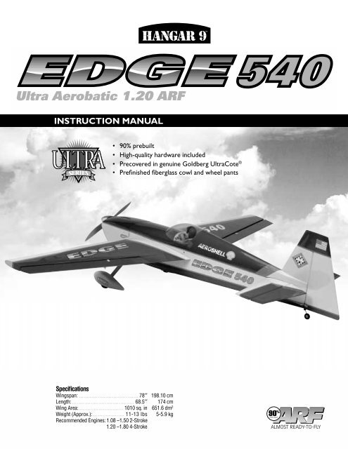
TMEDGE<strong>540</strong>Ultra Aerobatic 1.20 ARFINSTRUCTION MANUAL• 90% prebuilt• High-quality hardware included• Precovered in genuine Goldberg UltraCote ®• Prefinished fiberglass cowl and wheel pantsSpecificationsWingspan: . . . . . . . . . . . . . . . . . . . . . . . . . . . . . . . . . . . . . . 78′′ 198.10 cmLength: . . . . . . . . . . . . . . . . . . . . . . . . . . . . . . . . . . . . . . . . 68.5′′ 174 cmWing Area:. . . . . . . . . . . . . . . . . . . . . . . . . . . . . 1010 sq. in 651.6 dm 2Weight (Approx.): . . . . . . . . . . . . . . . . . . . . 11-13 lbs 5-5.9 kgRecommended Engines: 1.08 –1.50 2-Stroke1.20 –1.80 4-Stroke90 %PRE-BUILT
IntroductionThank you for purchasing the <strong>Hangar</strong> 9 <strong>Edge</strong> <strong>540</strong>. This is the latest aerobatic line of fine ARFs (Almost-Ready-to-Fly) produced by<strong>Hangar</strong> 9. The <strong>Edge</strong> <strong>540</strong> is a high-performance aircraft best suited for the more experienced flyer and modeler. Although this is anARF, it does have some construction features that can be challenging for a new modeler. If you encounter difficulty in any constructionsequence, please contact one of our technicians. We provide any assistance we can concerning the construction of your <strong>Edge</strong> <strong>540</strong>.Please feel free to contact us at:Horizon Hobby, Inc.4105 Fieldstone RoadChampaign, IL 61822(877) 504-0233www.horizonhobby.comWarningAn R/C aircraft is not a toy! If misused, it can cause serious bodily harm and damage to property. Fly only in open areas, preferablyAMA (Academy of Model Aeronautics) approved flying sites, following all instructions included with your radio and engine.Additional Required EquipmentRadio Equipment4 channels minimum5 servos (50 in/oz plus servo for standard flyingand 90 in/oz plus servos for 3-D flying)1100mAh Receiver Battery (JRPB4240)Y-Harness (if not using a computer radio) (JRP133)12” Aileron Extensions (2) (JRPA098)Recommended JR Radio Systems:JR400EX JR XP783JR 421EX JR XP8103JR XP652 JR PCM10XEngine Requirements:1.08 – 1.48 2-cycle engines1.20 – 1.80 4-cycle enginesRecommended 2-Cycle Engines Recommended 4-Cycle EnginesWebra 1.20 Saito 1.20 – 1.80Moki 1.35Saito 1.20 GK – 1.80 GKMDS 1.48MDS 1.48Saito 1.80Additional Items12” Aileron Extension (2) (JRPA098)3” Tru-Turn Spinner (TRU 3002)True Turn Adapter for specific enginePropeller:MDS 1.48 = 16” x 8” (recommended)Saito 1.80 = 16” x 8” (recommended)Fuel tubingFuel Dot (HAN115)Pitts style muffler forspecific engine (if using MDS 1.48)Fuel Filter (HAN143)Foam for cushioning radio and fuel tank(DUB513)Antenna Tube (HAN112)Optional ItemsPilot figure (HAN8272 or HAN8275)Instrument Panel (HAN186)3
Tools and Supplies RequiredAdhesivesThin CA (Cyanoacrylate) glueThick CA (Cyanoacrylate) glue6-Minute Epoxy (HAN8000)30-Minute Epoxy (HAN8002)Masking tapeThreadlock Z-42 (Pacer)Canopy Glue (Pacer PAAPT56)Silver Solder (Staybrite)ToolsDrillDrill bits: 1/16'', 1/18'', 5/32'', 1/14''Soldering ironPhillips screwdriverZ-bend pliersCA remover/debonderStandard pliersMixing sticks5/32” hex wrenchMedium sandpaperMoto-tool with sanding drum and cut-off wheelHobby knife with #11 bladeEpoxy brushesScissorsStraight edgeRubbing alcohol1/16” hex wrenchSanding stick (medium)Small round filePaper towelsFelt-tipped pen or pencil90-degree triangleMeasuring device (36”)4
Contents of KitLarge PartsFuselage (HAN1351)Left Wing Half with Aileron (HAN1352)Right Wing Half with Aileron (HAN1352)Vertical Stabilizer with Rudder (HAN1353)Horizontal Stabilizer with Elevator(s) ( HAN1353)Cowl (HAN1354)Wheel Pants (HAN1355)Hatch (HAN1358)Other PartsMain landing gear (HAN1356)Wheels (2) (HAN2027)Fuel tank and hardware (HAN1460)Trim sheets (HAN1359)Metal motor mount and hardware (HAN2033)Tail wheel assembly (HAN2026)Canopy (HAN1357)Note: Instrument Panel (HAN186) is optional.1/4 scale pilot optional (HAN8272 or HAN8275)5
Section 1: Hinging the AileronsParts Needed• Right wing panel with aileron and hinges• Left wing panel with aileron and hingesTools and Adhesives Needed• Instant thin CA glue• CA remover/debonder• Paper towels• T-pin (one for each hinge)(optional procedure)Note: The control surfaces, including the ailerons, elevators,and rudder, are prehinged with hinges installed, butthe hinges are not glued in place. It is imperative thatyou properly adhere the hinges in place per the stepsthat follow using a high-quality thin CA glue.Step 1. Carefully remove the aileron from one of the wingpanels. Note the position of the hinges. The <strong>Edge</strong> <strong>540</strong> comeswith high-quality CA-type hinges.Step 2. Remove each hinge from the wing panel and aileronand place a T-pin in the center of each hinge. Slide each hingeinto the aileron until the T-pin is snug against the aileron. Thiswill help ensure an equal amount of hinge is on either side ofthe hinge line when the aileron is mounted to the wing panel.Step 4. Deflect the aileron and completely saturate each hingewith thin CA glue. The aileron’s front surface should lightlycontact the wing during this procedure. Ideally, when the hingesare glued in place, a 1/64” gap or less will be maintainedthroughout the length of the aileron to the wing panel hinge line.Note: The hinge is constructed of a special material thatallows the CA to wick or penetrate and distributethroughout the hinge, securely bonding it to thewood structure of the wing panel and aileron.Step 3. Slide the aileron on the wing panel until there is only aslight gap. The hinge is now centered on the wing panel andaileron. Remove the T-pins and snug the aileron against the wingpanel. A gap of 1/64” or less should be maintained between thewing panel and aileron.Step 5. Turn the wing panel over and deflect the aileron in theopposite direction from the opposite side. Apply thin CA glue toeach hinge, making sure that the CA penetrates into both theaileron and wing panel.6
Section 1: Hinging the AileronsCONTINUEDSealing the Hinge GapsIt’s imperative that the aileron and elevator hinge lines be sealedairtight to prevent flutter. Sealing the hinge line has severaladvantages. A sealed hinge line gives a greater control responsefor a given control deflection. It also offers more precise,consistent control response and makes trimming easier.Sealing the aileron and elevator hinge line ismandatory. Failure to do so may cause control surfaceflutter, resulting in a crash.Step 6. Using CA remover/debonder and a paper towel,remove any excess CA glue that may have accumulated on thewing or in the aileron hinge area.Step 9. Cut a piece of clear or blue UltraCote ® (not included)for sealing the ailerons to approximately 3'' x 28''. Fold theUltraCote ® down the center with the adhesive side to the outsidemaking a sharp crease at the fold.Step 7. Repeat this process with the other wing panel, securelyhinging the aileron in place.Step 10. Using a ruler, measure 3/8'' from the folded creaseand mark two places with a pen.Step 8. After both ailerons are securely hinged, firmly graspthe wing panel and aileron to make sure the hinges are securelyglued and cannot be pulled out. Do this by carefully applyingmedium pressure, trying to separate the aileron from the wingpanel. Use caution not to crush the wing structure.Note: Work the aileron up and down several times to “workin” the hinges and check for proper movement.7
Section 1: Hinging the AileronsCONTINUEDSealing the Hinge Gaps (continued)Step 11. Using a sharp #11 blade and a straight edge, carefullycut through both layers of UltraCote ® covering at the 3 /8'' pointmarked in Step 2.Step 14. Fully deflect the aileron in the up position. Place thestraight edge over the hinge line covering that you just ironeddown in Step 5 with the edge of the straight edge placed firmly atthe bottom of the hinge line as shown. Iron down this side of thecovering, making sure the aileron is fully deflected.Step 12. Mark and cut the folded covering to an overall lengthof 25 5 /6''. This piece will be inserted and ironed down into thehinge bevel on the bottom of the aileron.Step 13. Remove the backing from the UltraCote ® . Place thefolded crease side into the center of the hinge line on the bottomof the wing. Using a straight edge as shown, hold one side of theovering in place while ironing down theopposite side with asealing iron. We recommend setting the iron temperature to320° for this operation.8
Section 2: Joining the Wing HalvesParts Needed• Right/left wing panels• Dihedral brace• Plywood wing dowel plate• Wooden dowels• Wing bolt plates• Wing trim tapeTools and Adhesives Needed• 30-minute epoxy• 6-minute epoxy• Mixing stick• Epoxy brush• Masking tape• Hobby knife w/#11 blade• Rubbing alcohol• Paper towels• Wax paper• Ruler• Felt-tipped pen or pencil• Medium sandpaperStep 1. Locate the plywood wing joiner. Using the ruler,determine the center of the wing joiner and mark it with a felttippedpen or pencil.Step 4. Mix approximately 1 ounce of 30-minute epoxy.Note: It is extremely important to use plenty of epoxy whenjoining the wing panels together. It will also be helpfulto use wax paper under the wing center when epoxyingthe wing panels together.Step 5. Using an epoxy brush or a scrap piece of wood, apply agenerous amount of epoxy into the wing dihedral cavity in onewing panel.Step 2. Trial fit the wing joiner into one of the wing panels. Itshould insert smoothly up to the center line marked in Step 1.Now slide the other wing panel onto the wing joiner until thewing panels meet. If the fit is overly tight, it may be necessary tosand the wing joiner.Step 6. Coat one half of the wing joiner with epoxy up to theline marked in Step 1. Install the epoxy-coated side of thedihedral brace into the wing panel cavity up to the markedcenter line.Step 3. The correct dihedral angle for the wing is 0 degrees (atthe center line). Place the wing on a large flat surface one wingpanel resting on the flat surface. The other wing tip should be at1 1 /8'' in height from the surface (see illustration below). Ifnecessary, sand the wing joiner until this is achieved. Thereshould be no gaps in the wing center. Once you are satisfiedwith the fit, remove the wing joiner from the wing panels.0 °Flat Surface1 1 /8''9
Section 2: Joining the Wing HalvesCONTINUEDStep 7. Apply a generous amount of epoxy into the other wingpanel cavity.Note: You may need to mix up more epoxy to complete thejoining process.Step 9. Carefully slide the two wing halves together and firmlypress them together, allowing the excess epoxy to run out. Thereshould not be any gap in the wing halves. Use rubbing alcoholand a paper towel to clean up any excess epoxy.Step 8. Now apply epoxy to all sides of the exposed wingjoiner and uniformly coat both wing roots with epoxy.Step 10. Apply masking tape at the wing joint to hold the winghalves together securely. Place the wing on a flat surface. Withthe center wing panels firmly supported to lay flat on the surface,the wing tips should be propped up so it is 1 1 /8'' from the surface.Apply more masking tape the center wing joint and recheck the1 1 /8'' measurement. Allow the wing joint to dry overnight.Note: It is useful to use wax paper underneath the wingcenter while the epoxy is curing. This will help preventexcess epoxy from adhering to the work surface.10
Section 2: Joining the Wing HalvesCONTINUEDStep 14. Locate the yellow and blue center trim tape. Apply aportion to the center of the top and bottom of the wing centerafter the epoxy has cured from Step 13.Step 11. Allow the wing center joint to completely cure, thenremove the masking tape.Step 12. You can mount the two yellow-covered plywood rearwing bolt plates next.Note: The covering will have to be trimmed away fromthe area of the top of the wing so the pieces can beepoxied to the wing. Use care not to cut into the woodstructure of the wing.Trial fit the pieces, marking their location. Use a sharp hobbyknife to trim away the covering over the bolt holes..Step 13. Mix 1/4 ounce of 6-minute epoxy and epoxy the wingbolt plates to the top of the wing. The wing bolt plate holes willbe drilled out later.11
Section 3: Installing the Aileron ServosParts Needed• Left/right wing halves• Servos (2)• Servo extension(s) (2-12” recommended)• Y-harness (if using a non-computer radio)• String and a weight to run servo extensionsthrough the wingTools and Adhesives Needed• Hobby knife• Phillips screwdriver• Drill• Drill bit: 1/16”• Masking tape• Electrical tape• Pencil or felt-tipped penStep 1. Locate the servo opening in one of the wing halves.Install the recommended servo hardware supplied with your radiosystem onto your servos (grommets and eyelets). Install a servoextension lead to the servo (a 12” extension is recommended).Secure the connectors by tying a knot in the leads and wrappingwith electrical tape. This will prevent the connectors frombecoming accidentally disconnected inside the wing.Step 3. With the servo in place, mark the location of the servoscrews used to mount the servo to the plywood servo rail insidethe wing servo opening.Step 4. Using a 1/16”drill bit, drill the servo screw locationsmarked in the previous step.Step 2. Trial fit the servo into the servo opening.Trimmingmay be required, depending on the type of servo installed.Step 5. Before mounting the servo, run the servo lead andextension through the wing and out the opening provided nearthe wing center. The servo lead exit is located on the top of thewing. Turn the wing over and look for an opening near the centerof the wing close to where the wing joiner slot is.12
Section 3: Installing the Aileron ServosCONTINUEDStep 6. Use a piece of string with a small weight (bolt fromengine mounting hardware) attached as a device to attach to oneend of the servo lead extension and thread through the servoopening, through the wing, and out the servo lead exit. Othermethods can be used to thread the servo leads through the wing,but we have found this method is the quickest.Step 9. Repeat the procedure for the other wing half .Note: If you are using a non-computer radio, it will benecessary to use a Y-harness to connect both aileronservos to the aileron channel of the receiver.Step 10. Insert the servo into the cutout in the bottom of thewing. Make sure the output shaft of the servo is orientatedclosest to the leading edge of the wing.Step 7. Once you have threaded the string and weight throughthe wing, attach the string to one end of the servo lead andcarefully thread it through the wing. Once you have threaded thelead through the wing, remove the string so it can be used forthe other servo lead.Step 11. Use the screws included with the servos to fasten theaileron servos in place.Step 8. To prevent the lead from falling back into the wing, usemasking tape to temporarily hold it in place by taping the lead tothe top of the wing.13
Section 4: Installing the Aileron LinkagesParts Needed• Wing assembly from Section 2• Left control horn• Right (reversed) control horn• Plastic plate (2)• Screws (8)• Short (3-3/4” x 4-40) threaded rod (both ends)(2)• 4/40 metal clevis (4)• Locking clips for clevis (4)• 4/40 nuts (4)• Heavy duty servo arm (JRPA215) (Optional for 3-D throws)Tools and Adhesives Needed• Phillips screwdriver• Drill• Drill bits: 1/16”, 3/32”• Felt-tipped pen or pencil• Moto-tool (optional)Step 1. For this assembly, you will be using two 3-3/4”threaded rods, four clevis, four 4-40 nuts, and a regular and areverse metal control horn. Use the 4-40 nuts as locking devicesto keep the clevis from turning. There is also a locking clip thatkeeps the clevis from opening. The reverse control horn has an“R” marked on its base; the standard horn has no marking. Forillustration purposes, we will describe the installation of theaileron linkage on the right wing panel (bottom).Step 4. The servo arm should be positioned so it is pointing tothe wing tip. When installing the control horn, the holes in thecontrol horns (where the pushrod attaches) should be in linewith the control surface hinge line.Note: If using 3-D throws, use a heavy duty servo arm(JRPA215 for JR Servos.)Step 2. Thread a 4-40 nut and clevis on each end of thethreaded rod. Next locate the standard horn. The link assemblygoes on the 2nd outer hole from the end as shown below.Step 5. Once you are satisfied with the metal control hornlocation (it should be a straight line from the servo arm to thehorn), mark the location of the screw holes with a felt-tipped penor pencil. The hinge line and the control rod should be at90-degree angle to achieve proper mechanical efficiency.Step 3. The metal clevis will attach to the servo arm that pointsto the wing tip. If you wish, the other three arms can be trimmedoff. To establish the position of each of the clevis on the threadedrod, trial fit the horn and linkage to the servo arm. Adjustmentsin length are made by screwing one or both clevises in or out.14
Section 4: Installing the Aileron LinkageCONTINUEDStep 6. Use a 3/32” drill bit to drill the screw holes formounting the control horn. We suggest you apply a thin coat ofCA into the aileron through the drilled holes help stiffen thebalsa in the mounting area.Step 8. Repeat the process for the other aileron on the otherwing panel.Note: The control horn mounting screws may beexcessively long on some control surfaces, and youmay wish to cut off the excess using a Moto-tool andcut-off wheel. Leave a minimum of 1/8” of mountingscrew above the plastic plate.Step 7. Attach the control horn to the aileron using four screwsand the plastic plate. Be careful not to accidentally puncture thecovering with the screwdriver. We suggest putting masking tapearound the horn area to help protect it from dents or scrapes.15
Section 5: Mounting the Wing to the FuselageParts Needed• Wing• Fuselage• Wing hold down hardwareTools and Adhesives Needed• Hobby knife with #11 blade• 30-minute epoxy• Epoxy brush• Mixing stick• Rubbing alcohol• Felt-tipped pen or pencil• Pliers• Ruler• Drill• Drill bit, 1 /4”• Round fileStep 1. Locate the forward mounting bolt holes in the wing.Trim the covering from the mounting bolt holes with a sharphobby knifeStep 2. Place the wing onto the fuselage. Use care as the firstfew times the wing is inserted, the fit is snug. Note the tolerancebetween the wing and the fuselage. There is little movement ofthe wing once it is in the fuselage wing saddle area. You cancheck the alignment of the wing to the centerline of the fuselageby making a reference mark at the tail of the fuselage, thenmeasuring each wing tip to make sure the wing is aligned.Step 3. With the wing centered in the fuselage wing saddlearea, secure it with masking tape so it will not move from side toside. Measure from wing-tip to the center of the fuselage at therear. When you are satisfied with the alignment then proceed.Step 5. Use the holes in the top wing bolt plates at the trailingedge of the wing as a guide to drill two holes into the plywoodwing support at the rear of the hatch area in the fuselage. Again,drill at 90 degrees to the wing chord line.Step 6. Remove the wing from the fuselage. Trial fit the blindnuts into position under the fuselage plywood wing supports atthe front and back of the fuselage hatch opening. Use pliers withan adjustable opening to squeeze the blind nuts into position sothe “teeth” penetrate the wood and stay in place.Note: It is a good idea to place a piece of scrap wood on thetop side of the plywood wing hold down blocks whenpressing the blind nuts into place.EDGE <strong>540</strong>EDGEUltra Aerobatic 1.20 ARF<strong>540</strong>Ultra Aerobatic 1.20 ARFStep 4. Using the front wing bolt holes as a guide, drill throughthe wing and plywood wing support in the fuselage with a 1 /4”drill bit. Drill 90 degrees to the centerline of the wing chord.16
Section 5: Mounting the Wing to the FuselageCONTINUEDStep 7. Once the blind nuts are in place, trial fit the wing ontothe fuselage and insert the nylon mounting bolts. Tightenenough to hold the wing in place but do not completely tighten.Check the alignment of the wing to the reference point on thefuselage again as done in Step 2. When you are satisfied withthe alignment, tighten securely. Remove the bolts and wing.Apply some 30-minute epoxy to the blind nuts to secure them.Section 6: Installing the TailFuselage Parts Needed• Fuselage• Wing• Horizontal stabilizer with elevators• Vertical stabilizer with rudderTools and Adhesives Needed• Thin CA glue• CA Remover/debonder• 30-minute epoxy• Epoxy brush• Mixing stick• Hobby knife with #11 blade• Straight edge (36”)• Felt-tipped pen or pencil• Masking tape• Rubbing alcohol• Paper towels• Ruler• 90-degree triangleStep 1. On the rear of the fuselage, carefully remove the tapeholding the shaped fairing blocks onto the fuselage. Note theyare in two separate pieces and fit over the horizontal stabilizerand around the vertical stabilizer.17
Section 6: Installing the TailCONTINUEDStep 2. Trim away the covering over the elevator and rudderlinkage openings on both sides of the fuselage at the tail. Lookcarefully, and you will see the slots. Trim away the coveringusing a sharp hobby knife.Step 5. Attach the wing and measure from the front tips of thehorizontal stabilizer to the wing tips. Each should be the samedistance from the wing. Make any adjustments necessary tomake sure the horizontal stabilizer is aligned with the wing.Step 3. Carefully remove any the tape holding the elevators tothe horizontal stabilizer and remove the elevators. Measure thecenter of the fuselage at the forward bulkhead where the front ofthe horizontal stabilizer will rest, and the plywood plate at therear or the fuselage. Using a ruler, mark the center line of thehorizontal stabilizerEDGE <strong>540</strong>EDGEUltra Aerobatic 1.20 ARF<strong>540</strong>Ultra Aerobatic 1.20 ARFStep 6. When you are satisfied with the position of thehorizontal stabilizer, use a felt- tipped pen or pencil to mark thebottom of the horizontal stabilizer next to the fuselage. Removethe horizontal stabilizer and trim away the covering 1/8” insidethe marks you made. Being very careful no to cut or evenscore the balsa wood below the covering. This willprovide for a more secure epoxy joint when the horizontalstabilizer is epoxied to the fuselage.Step 4. Trial fit the horizontal stabilizer onto the rear of thefuselage. Install the elevators to check the distance between themand the rear of the fuselage to make sure there is no binding.Note that the fit is very close. Use masking tape to hold thehorizontal stabilizer in place while making measurements. Checkto see if the elevators will function without binding when thehorizontal stabilizer is centered on the marks made in Step 3.Step 7. Reinstall the wing and mix approximately 2 ounces of30-minute epoxy. Apply the epoxy to the tail where the horizontalstabilizer will be mounted and to the bare wood of the horizontalstabilizer. Reposition the horizontal stabilizer to the fuselage,18
Section 6: Installing the Tailmaking sure you align it with the reference marks madepreviously. Then align the stab so that it is square with the wingwhen sighted from the front. Wipe away any excess epoxy withrubbing alcohol and a paper towel. Be sure there is no epoxy inthe area where the two tail pieces will go. Hold in position withmasking tape. Allow the epoxy to cure.CONTINUEDCaution: Do not cut into the wood below the covering.This will weaken the structure.Step 9. Mix approximately 1 ounce of 30-minute epoxy andapply to the vertical stabilizer and tail post where it contacts thefuselage and horizontal stabilizer. Be sure to apply epoxy to thebase of the vertical stabilizer. Insert the vertical stabilizer into thefuselage tail area and wipe away any excess epoxy with rubbingalcohol and a paper towelStep 10. Mix approximately 1 ounce of 30-minute epoxy.Apply epoxy to both fairing blocks and mount to the horizontaland vertical stabilizers. Wipe away any excess epoxy. Usemasking tape to hold the two fairing blocks in place.Step 8. Carefully remove the tape holding the rudder to thevertical stabilizer. Trial fit the vertical stabilizer to the fuselageand trial fit the two fin fairing blocks. Some trimming of thefairing blocks may be necessary to obtain a good fit. Hold inplace with masking tape.Mark the position where the vertical stabilizer meets thetailpieces with a felt-tipped pen or pencil. The mark should leavea slight indentation in the covering. Carefully remove the verticalstabilizer and tail pieces. Remove the covering 1/8” from whereyou made the marks, using the procedure as described in Step 6.19
Section 6: Installing the TailCONTINUEDStep 11. Carefully check the alignment of the vertical stabilizerto the horizontal stabilizer. A 90-degree triangle is helpful here.Use masking tape to hold the components in alignment. Allowthe epoxy to dry completely cured.Section 7: Hinging the Horizontal Stabilizerand Elevator(s)Fuselage Parts Needed• Fuselage with Vertical and horizontal stabilizers attached• Elevators (2)Tools and Adhesives Needed• Thin CA glue• CA remover/debonder• Paper towels• T-pinsStep 1. Locate the elevator and hinges. Carefully remove thetape holding the elevators in place. Fit the elevators into theproper position on the horizontal stabilizer, using the samehinging techniques learned in Section 1. Check to make surethere is no binding of movement.Step 2. With one elevator half properly aligned (left and right),apply thin CA glue to the hinges on both sides (be sure toremove the t-pins first). Wipe away any excess CA with CAdebonder and a paper towel.20
Section 7: Hinging the Horizontal Stabilizerand Elevator(s)CONTINUEDStep 3. After the hinges are dry, check that they are securely inplace by trying to pull the elevator from the horizontal stabilizer.Caution: Use care not to crush the structure.Step 4. Repeat steps 1-3 for the other elevator halfStep 5. Work the elevators up and down several times to “workin” the hinges and check for freedom of movement.Section 8: Hinging the Rudder and Installingthe Tail WheelFuselage Parts Needed• Rudder• Fuselage• Tail wheel assemblyStep 1. Trial fit the rudder in position on the Vertical Stabilizerwith the hinges in place.Tools and Adhesives Needed• Thin CA glue• CA remover/debonder• Threadlock Z-42• 30-minute epoxy• Mixing stick• Epoxy brush• Drill• Drill bits: 1/16”, 3/32”• Needle-nose pliers• Hobby knife with #11 blade• Felt-tipped pen or pencil• Paper towels• Rubbing alcohol• Masking tapeStep 2. Insert the tail wheel wire into the pivot bushing. Withthe pivot bushing resting against the bend in the tail wheel wire,use a needle-nose pliers to make a 90-degree bend in thedirection shown below in step 3, 1/8” above the top of the pivotbushing.Note: The part of the tail wheel wire that inserts into therudder must go into the wood in the rudder. To insureadequate strength, the bend of the wire must be keptas low as possible.21
Section 8: Hinging the Rudder and Installingthe Tail WheelCONTINUEDStep 5. Using a hobby knife or a Moto-tool, cut a slot orgroove into the back of the fuselage vertical stabilizer as markedin Step 3. This groove will be used to accept the tail wheel pivotbushing.Step 3. Hold the tail wheel assembly up to the fuselage in aposition where it’s flush with the fuselage bottom. Note wherethe wire rests in reference to the rudder. Use a felt- tipped pen orpencil to mark the position where the hole for the wire is to bedrilled into the rudder. Also mark the position of the slot for thepivot bushing will be located in the rear of the fuselage.Step 6. Trial fit the tail wheel assembly and rudder in placewith the hinges. Deflect the rudder, making sure the tail wheelturns freely with the rudder and there is no binding.Step 4. Remove the rudder from the vertical stabilizer. Use a3/32” drill bit to drill a hole in the exact center of the rudder asmarked for the tail wheel wire to be inserted in the rudder. Drill a1/16” pilot hole first.Step 7. When you are satisfied with the fit, disassemble therudder and tail wheel assembly. Mix approximately 1 oz of30-minute epoxy and apply to both the pivot bearing, the slot forthe pivot bearing and in the hole for the tail wheel wire to beinserted into the rudder. You can use masking tape to hold inplace while the epoxy cures. With the hinges in place,reassemble the tail wheel assembly and rudder. Wipe away anyexcess epoxy with alcohol and a paper towel. Allow the epoxy tocure completely before gluing the rudder hinges with CA.22
Section 8: Hinging the Rudder and Installingthe Tail WheelCONTINUEDStep 8. With the rudder aligned (up and down), apply thin CAglue to the rudder hinges on both sides of the rudder, using thesame technique used in Section 1. Wipe away any excess CAwith CA remover/debonder. After the hinges are dry, check thatthey are securely in place by trying to pull the rudder from thevertical stabilizer and fuselage. There should be a minimal gap( 1 /64”) between the rudder and the vertical stabilizer.Step 9. Work the rudder right and left. Check for free movementand ensure that the tail wheel tracks accordingly.Step 10. Slide the tail wheel onto the wire. Next, slide the wheelcollar onto the wire and tighten the screw in the wheel collarusing the hex wrench provided. Use Locktitej® Z-42 to securethe wheel collar screw in place.Note: The wheel must rotate freely with only a small amountof side play. It may be necessary to drill out the tailwheel slightly so the wheel will spin freely on the axle.Section 9: Installing the Control HornsFuselage Parts Needed• Standard/reverse control horns (2 each, 4 total)• Plastic plates (3)• Screws (12)• Fuselage with rudder and elevators installedTools and Adhesives Needed• Standard screwdriver• Thin CA glue• CA debonder/remover• Paper towel• Drill• Drill bits, 1/16”, 3/32”• Ruler• Felt-tipped pen or pencil• Masking tapeStep 1. Locate a standard and reverse control horn and theassociated hardware. Note that on the bottom of the controlhorn, the one with no markings is the standard horn and the onewith the “R” is the reverse control horn. The right (as relates tothe pilot sitting in the cockpit) elevator uses the standard horn,the left elevator uses the reverse horn.Step 2. It will be helpful to turn the aircraft upside down. Forillustration purposes we will describe installing the control hornon the right elevator first (as relates to the pilot sitting in thecockpit). Measure 1/2'' out from the fuselage and mark.23
Section 9: Installing the Control HornsCONTINUEDStep 3. Locate the standard control horn. Trial fit the horn onthe elevator with the flat part towards the tip of the elevator andthe part that connects to the clevis being closer to the fuselage.Step 4. Line up the inside edge of the horn with the edge of theelevator and the mark you made in step 2. Make sure the horn iscentered on the wood frame of the elevator. Mark the screw holeswith a felt-tipped pen or pencil.Step 6. Carefully install the screws and engage the plastic plateon the other side. We suggest you cover the area with maskingtape around the horn to prevent damage to the covering if thescrewdriver slips. Once the right elevator control horn isinstalled, repeat the process for the left elevator.Step 7. Locate a standard and reverse control horn, fourscrews, and one plastic plate. The reverse “R” control horn isinstalled on the right side of the rudder (as if you were sitting inthe cockpit). The standard control horn will be mounted on theleft. These make up the rudder pull-pull control horns. They arelocated up from the bottom of the rudder along the edge of thered trim and the front edge is flush with the bevel. Mark thelocation with a felt-tipped pen or pencil. Trial fit one horn andmake sure the location does not interfere with the tail wheel wirethat was inserted into the rudder.Step 8. Once you are satisfied with the location, mark the screwholes with a felt-tipped pen or pencil.Step 5. Using a 1/16” drill bit, drill four holes for the horn.After the pilot holes are drilled, you can use the 3/32” bit tocomplete the process. After the holes are drilled, apply thin CAglue to the holes and area around the holes to help strengthenthe balsa of the elevator. Allow the CA to dry, then re-drill toclear any obstruction caused by the glue. Caution: The balsa issoft so be sure to use CA to strengthen the mounting of thecontrol horn.24
Section 9: Installing the Control HornsCONTINUEDStep 9. Drill the holes using the same technique as describedin step 5. Use caution not to damage the covering.Step 10. Mount the two horns on the rudder, one on eitherside, with the standard horn on the left side and the reverse hornon the right side. The plastic plate will be used as a retainer onone side. Use caution when screwing in the screws so that thecovering is not damaged if the screwdriver slips.25
Section 10: Installing the Main Landing GearParts Needed• Fuselage• Main landing gear• Mounting hardwareTools and Adhesives Needed• Hobby knife with #11 blade• Phillips screwdriver• Felt-tipped pen or pencil• Locktite ® Z-42Step 1. Locate the three mounting holes for the landing gear onthe forward part of the bottom of the fuselage. Look carefully asthe covering may make it difficult to find them. The blind nuts arealready mounted inside the fuselage. Use a hobby knife andremove the covering from the mounting holes.Step 3. Using the hardware provided, mount the main landinggear to the fuselage. Apply Locktite Z-42 to the threads of thescrews to help secure them to the blind nuts in the fuselage.Step 2. Trial fit the aluminum main landing gear over the holesin the fuselage.26
Section 11: Assembling and Mountingthe Wheel PantsParts Needed• Wheel pants• Wheels (2)• Main landing gear• Mounting hardware packageTools and Adhesives Needed• Ruler• Phillips screwdriver• Drill bits: 1/4'', 3/32'', 1/8'', 1/2''• Drill• 30-minute epoxy• Epoxy brush• Mixing stick• Rubbing alcohol• Paper towel• Round file (fine)• Sandpaper (medium)• Felt-tipped pen orpencilStep 1. Locate the two wheel pants and associated hardware,including the two 1 1 /8'' square plywood pieces that go inside thewheel pants. Slide one wheel onto an axle and position them sothey are centered over the wheel opening in one of the wheelpants. Use a felt-tipped pen or pencil to mark the center locationof the wheel on each of the wheel pants. This mark will be usedas the reference point for marking the mounting holes for thelanding gear on the wheel pant.Note: It is sometimes helpful to remove the main landinggear from the fuselage to make these markings andadjustments called for in the following steps.Step 3. Trial fit the wheel pant on the landing gear and note thelocation of the main axle. Note the aluminum landing gear has alarge hole (for the axle) and a smaller hole above it. This smallerhole will be used to secure the wheel pant in the proper positionrelative to the fuselage. Do not mark the small hole yet.Step 4. Drill the main axle hole using a 1/2'' drill bit. It ishelpful to start with a 1/8'' pilot hole first. Once the hole is drilled,trial fit the axle to the opening again. You may have to enlargethe hole further. Use a fine round file to make final adjustmentsto the opening. Repeat the process for the other wheel pant. Besure to drill on the opposite side of the other wheel pant.Step 2. Locate the hole for the wheel axle 5/8'' measured upfrom the bottom of the wheel pant centered on the mark madein Step 1. Mark with a felt-tipped pen or pencil. Repeat the procedurefor the other wheel pant. Notice which side of the wheelpant goes against the landing gear before making your mark.Step 5. Locate the two plywood square pieces included with thewheel pants. These will be epoxied inside the wheel pants as areinforcement for mounting the wheel pant to the landing gear.Using the landing gear as a template, mark the plywood squares:one for the large axle hole and the other small hole that will beused by the 4-40 bolt and blind nut to hold the wheel pant inposition.27
Section 11: Assembling and Mountingthe Wheel PantsCONTINUEDStep 9. The wheel pant can be trial fitted to the landinggear/axle. You may find you will have to open up the large axlehole a bit with a round file due to epoxy seeping into theopening. Adjust the wheel pant in reference to the bottom of thefuselage so the bottom of the wheel pant is parallel to the bottomof the fuselage. When you are satisfied with the alignment, markthe small hole opening onto the wheel pant.This mark can bemade by passing a small drill bit through the hole and markingthe surface of the wheel pant. Remove the wheel pant and drill a3/32” hole in the wheel pant as marked.Step 6. Use a 1/4” drill bit and a 1/8” drill bit to drill out theholes in the plywood squares for the axle and 4-40 bolt. Usecaution that you do not split the wood.Step 10. Repeat Step 9 for the other wheel pant.Step 11. Epoxy a 4-40 blind nut into the small hole drilled in thewheel pant /plywood brace inside the wheel pant. Allow the epoxyto cure completely before attempting to tighten the bolt down.Step 12. Mount the wheel pant to the axle and screw in the4-40 bolt into the small hole above the axle, so that it screwsinto the blind nut. Before tightening the 4-40 bolt, slide on awheel collar, the wheel, and another wheel collar onto the axle.Step 13. Tighten down the 4-40 bolt to secure the wheel pant tothe landing gear. Position the wheel in the center of the wheelpant opening, and retain it there by positioning the two wheelcollars (on either side of the wheel) so that the wheel is kept inthe center of the wheel pant opening. Tighten both wheel collarscrews snugly once the wheel is properly positioned.Step 7. Mix approximately 1 ounce of 30-minute epoxy. Epoxyboth plywood pieces to the inside of each wheel pant, makingsure the epoxy does not clog the openings in the wheel pant thatwere drilled. The smaller hole will have to be drilled out later.Note: A drop of Locktite ® Z-42 on the wheel collar screwswill help keep them from coming lose duringoperation. Repeat the process for the other wheel.Step 8. Locate the axle, lock nut, wheel, and two wheel collars.Mount both axles to the landing gear using the large lock nuts.Once mounted, you will have to trim each axle using a Moto-tooland a cut-off wheel. Use caution when cutting the axles and wearprotective goggles.28
Section 12: Installing the EngineParts Needed• Fuselage• Metal motor mounts• Mounting hardware• Engine• Spacer Plate (If using MDS 1.48)Step 1. Mix approximately 1 ounce of 30-minute epoxy and anequal amount of rubbing alcohol. Brush the mixture on thefirewall (and spacer plate) to seal it to make it fuelproof. Allowthe epoxy to cure completely.Step 2. Locate the two metal motor mounts and associatedmounting hardware. Note the motor mount screw holes areshaped like slots in the firewall. This is to allow moving themotor mounts closer or further apart so engines of differentwidth crankcases can be mounted. Note also that the motormount can only be installed so the engine cylinder faces to theright side of the aircraft, as seen from the cockpit of the model.Tools and Adhesives Needed• Phillips screwdriver• 30-minute epoxy• Rubbing alcohol• Epoxy brush• Mixing stick• Paper towel• Locktite ® Z-424 nuts provided. Adjust the distance between the metal motormounts until the engine crankcase fits the motor mount. Checkthe metal motor mount position on the firewall, making sure themounts are parallel to the bottom of the firewall. Once the properdistance between the motor mounts is determined and they areparallel to the bottom of the firewall, tighten the bolts mountingthe motor mount to the firewall securely. A drop of Locktite Z-42on the bolt threads will help prevent loosening in flight.Step 5. Position the engine along the metal motor mount untilyou measure 6 1 /4” from the firewall to the front end of the propdrive hub.Note: If a shorter engine is used, such as MDS 1.48, the3/8'' plywood spacer plate must be used behind themotor mounts.Once the engine is in proper position, tighten down the motormounting bolts securely. Again, a drop of Locktite Z-42 will helpprevent loosening of the bolts in flight. The engine should bepositioned so there is ample clearance in the cowling for thespinner backplate mounted to the prop drive shaft. If you removethe engine and reinstall it, make sure the engine is mounted at thedistance previously mentioned. Remember, the key distance is fromthe prop drive hub to the firewall.Step 3. Mount the metal motor mounts on the firewall using thebolts and washers provided. The blind nuts are installed on theinside of the fuselage. Do not over tighten the bolts at this time,as the width of the mount will vary with the size of the enginecrankcase used.Step 4. Trial fit your engine on the motor mount by mounting itloosely to metal motor mount with the 4 bolts, 8 washers, and29
Section 13: Assembling and Installingthe Fuel TankParts Needed• Clunk (Fuel Pickup)• Tube (vent)• Tube (fuel )• Silicon fuel tubing• Fuel tank• Plastic cap (large)• Plastic cap (small)• Rubber stopper• 3 mm screw• 3 mm nutTools and Adhesives Needed• Hobby knife with #11 blade• Phillips screwdriver• Tubing bender (optional)• Tubing cutter (optional)Step 1. Locate the fuel tank parts.Step 3. Locate the other tube. This will be the vent tube. Bendone end up about 60 degrees but no more than 90 degrees.Caution: You can use your fingers to bend the tubing, but becareful not to kink the tubing. If you have access to a smalltubing bender, use it to make the bend. Refer to photo below.Step 2. Locate the rubber stopper. Insert on of the tubes into anopen hole in the stopper so an equal amount of tubing extendsfrom each side of the stopper. This tube will be the fuel pickuptube that provides fuel to the engine. Slide the smaller plasticcap onto the tube at one end, so that the three tabs will faceinside the tank. (These tabs will hold the 3mm nut in place later.)Slide the large plastic cap over the tube and against the rubberstopper. It should be orientated so that the “raised center” facesaway from the stopper.Step 4. Slide the vent tube into the other open hole in thestopper and caps.Note: An option is to trim the length of the vent and fuel pickuptubes with a tubing cutter. This makes a neater job.30
Section 13: Assembling and Installingthe Fuel TankCONTINUEDStep 5. Locate the piece of silicone fuel tubing and metal clunk.This tubing will be attached to the clunk making up the fuelpickup inside the tank. Insert the metal clunk into one end of thefuel tubing.Step 8. Carefully insert the stopper into the fuel tank. Positionthe stopper so the vent tube is pointing to the top of the fuel tank.The vent tube must point to the top of the tank for the fuel systemto function properly. Also, move the tank around and up anddown to observe the movement of the clunk. It should movefreely, and not hit the back of the fuel tank. The fuel clunk mustbe free to move, regardless of what attitude the aircraft takes,thus ensuring it is in the fuel at all times. If the clunk does notmove freely, trim a portion of the fuel tubing to shorten thelength and try again.TopStep 6. Install the open end of the fuel tubing onto the fuelpickup tube.Step 7. Insert the 3 mm screw into the raised portion of thelarge plastic cap. Place the 3mm nut into the raised slots on thesmall plastic cap. Compress the caps/stopper together andscrew the 3 mm screw into the nut. Tighten just enough to holdthe assembly together.Step 9. When you are satisfied with the movement of the clunk,and the vent tube is properly positioned to point to the top of thetank, tighten the 3 mm screw so the caps move toward eachother and compress the rubber stopper in the tank stopperopening. This compression will help seal the stopper into thetank opening.Important: You should mark which tube is the vent and which isthe fuel pickup when you attach fuel tubing to the tubes in thestopper. Once the tank is installed inside the fuselage, it may bedifficult to determine which is which.Step 10. Wrap the fuel tank in foam. This is done to providesupport for the fuel tank, and help reduce vibration. Attach fueltubing the tank tubes and feed the tubing through the hole in thefirewall as you slide the fuel tank into the area behind the firewallin the fuselage. You will note two “C” shaped slots in theplywood floor behind the firewall. Rubber bands are slipped intothese “C” shaped slots around the fuel tank, thus holding itfirmly in place.Note: Remove the fuel tank when drilling the hole for thethrottle linkage to prevent accidental puncturing of thefuel tank.31
Section 14: Installing the RadioParts Needed• 4-channel radio system with 5 servos and hardware• Radio packing foam• Antenna tube (HAN112) (optional)• SwitchTools and Adhesives Needed• Drill• 1 /16” drill bit• Phillips screwdriver• Hobby knife with #11 blade• Felt-tipped pen or pencil• 6-minute epoxy• Rubbing alcohol• Paper towels• Mixing stick• Epoxy brushStep 1. Locate the plywood servo rail (5/16 x 7 3 /4''). It will goin front of the servo rail already installed in the fuselage. Note the“U” shaped notch in the fuselage sides for placement of the servorail. Trial fit the servo rail in place, with the rudder and elevatorservos in place. When you have determined the proper spacing,mark the location of the rail to the fuselage sides with a felt-tippedpen or pencil. Remove the servos. Mix approximately 1/4 ounceof 6-minute epoxy and apply to the servo rail and fuselage sidesat the “U” location. Allow the epoxy to cure completely.Step 3. Install the rudder servo on the servo rails next. Place itso it is in the center of the fuselage, with the servo arm facingtoward the rear of the fuselage. The rudder servo uses a pull-pulllinkage so leave ample room between its servo arm and that ofthe elevator servo arm. Install the elevator servo next, placing itto the left (as if one were sitting in the cockpit of the aircraft) ofthe rudder servo. Make sure there is ample room between thetwo servo arms.Note: We recommend 1 1 /4'' servos arms for the rudder andelevator. If you are going to use 3-D throws, <strong>Hangar</strong> 9offers a variety of heavy duty gold-anodized machinedaluminum servo arms for 3-D flying. (HAN3576-3579)Step 2. Locate the throttle servo and install the grommets andeyelets per the instructions included with the radio. Do the samefor the rudder and elevator servos. Position the throttle servo inthe opening in the plywood floor near the fuel tank. Orient theservo so the servo arm is toward the front of the fuselage.Step 4. Once you’re satisfied with the servo’s location, use a felttippedpen/pencil to mark the mounting holes for all three servos.32
Section 14: Installing the RadioCONTINUEDStep 5. Remove the servos and drill the 12 holes using a1/16'' drill bit. Remount the servos and screw in the mountingscrews provided with the servos.Note: We wrapped the battery in foam and attached it to theplywood above the fuel tank directly behind thefirewall platform using Velcro ® . For the receiver, weused a J-TEC Pillow Pack, attached Velcro to theplywood floor behind the fuel tank next to the throttleservo, and also attached the receiver Pillow Pack tothe floor using velcro.Step 7. Route the antenna back through the fuselage using anantenna tube (not included), or route it out the side of thefuselage, back toward the tail. Install the switch to the left side ofthe fuselage under the wing, as shown below.Note: Trial fit the switch inside the fuselage to make sure youhave proper clearance.Step 6. Use radio packing foam (available at your local hobbyshop) when you install the receiver and battery pack. There isample room for the receiver and battery in the forward part of thefuselage, in the area above and behind the fuel tank. Wrap thebattery and receiver in foam and install them into the fuselage.Receiver InstallationReceiver Battery Installation33
Section 15: Installing the Control LinkagesParts Needed• Fuselage• Wood pushrod• Heat Shrink tubing• 12'' x 4-40 rod – threaded on one end (2)• 6'' x 4-40 rod – threaded on one end• 4-40 clevis w/clips (3)• 4-40 nuts (3)• 20'' x 2 mm rod - threaded on one end with nylon clevis• .020 music wire 36'' (2)• 2-56 clevis w/clips (4)• 2-56 threaded couplers (4)• 2-56 nuts (4)• Heavy-duty 1 1 /4'' servo arms for 3-D throws (optional)Tools and Adhesives Needed• Hobby knife with #11 blade• Soldering iron• Silver Solder (Staybrite)• Needle nose pliers• 30-minute epoxy• Nylon string• Rubbing alcohol• Paper towels• Mixing stick• Drill• 1/8” drill bitStep 1. The elevator linkage will be the first described. Thecomponents for the elevator control linkage consist of a woodpushrod, three threaded music wire rods, clevis w/clips, and apiece of heat shrink tubing. Since the <strong>Edge</strong> <strong>540</strong> uses a split (twopiece)elevator, you will construct a pushrod that has twothreaded rods on one to connect to the elevator control hornsand one threaded rod on the other end to connect to the elevatorservo arm.Step 3. Use a 1/8'' drill bit and drill the holes marked on thewood push rod. Round out the holes so the rods will fit flushagainst the wood push rod. A groove can be cut from the holesto the end of the wood push rod to help secure the rods in placewhen applying epoxy.Step 2. Trim 2 1 /2'' off of the wood pushrod before proceedingwith the marking of the wire rod position. Make a mark 1 1 /2'' fromone end, of the wood push rod with a felt-tipped pen or pencil.Make a second mark 2'' from the same end, but on the oppositeside of the wood pushrod. On the other end of the woodpushrod, make a mark 1 1 /2'' from the end, but make it 90 degreesfrom the other two marks. In effect you will have two rods at oneend on opposite sides from each other, and at the other end therod will be on the top/bottom side between the two.Step 4. Fit the two 12'' threaded rods on either side of the woodpushrod along side the holes drilled. Position the rods so thethreaded ends are the same distance from the end of the woodpushrod. Mark the rods at the 1 1 /2'' and 2'' hole positons.34
Section 15: Installing the Control LinkagesCONTINUEDStep 5. Make a 90-degree bend at the opposite (unthreaded)end of each 12'' rod at the positions marked in Step 4. Trim thebend section to a length of 1/8'' to 3/16'' (enough to fit in the holein the wood pushrod but not extend beyond the hole).Step 6. Trial fit the two long threaded rods into the hole oneither side of the wood pushrod (the 1 1 /2'' and 2'' marked end).Trim off any excess rod that projects beyond the hole. You mayneed to round out the holes slightly so the rods fit against thewood pushrod.Step 7. When you are satisfied with the fit, mix approximately1/4 ounce of 30-minute epoxy and apply to the holes and groovesof the wood pushrod. Install the rods into the holes and wrapsecurely with nylon thread. Coat with epoxy and allow to cure.Step 8. Cut the heat shrink tubing into two equal pieces. Slipone onto the wood pushrod and threaded rods. Use a heat gun toshrink the tubing into place.Step 9. If you have not cut out the openings for the elevator andrudder linkages on each side of the fuselage rear, now is the timeto do so. They are located below the front of the horizontalstabilizer. Both slots are approximately 1'' long. The elevator slotis approximately 1 3 /8'' below the front of the horizontal stabilizer,each side of the fuselage. The rudder pull-pull linkage opening islocated directly below the elevator linkage slot, along the red trimline at the fuselage bottom.Step 10. Slide the elevator pushrod through the hatch openingin the fuselage and into the tail section so that each rod exits atthe rear of the fuselage, through the elevator linkage slots.Hint: The elevator pushrod requires some bending of thethreaded rods that pass through the fuselage rear. Theillustration below gives an approximate idea of how tobend the rods so they would exit the fuselage.2''1''30° Approx.Attach a nut and a clevis to each elevator threaded pushrod end.Screw in approximately 10 turns. Connect each clevis to theouter hole of each elevator control horn. Adjustments to eachelevator position can be done by screwing the clevis in or out onthe threaded rods. The clevis should be secured to the controlhorn with the metal clips provided with each clevis. This willprevent the clevis from opening in flight.Step 11. With the pushrod attached to the elevators, adjust soeach elevator half moves the same. Tape the elevators in theneutral position (centered to horizontal stablizer). Attach the6'' threaded rod to the other end of the wood pushrod, threadedend toward the elevator servo in the fuselage. Make sure theelevator servo arm is centered. Thread a nut and clevis on thethreaded end of the 6'' rod and adjust the rod so the servo arm is90 degrees to the elevator push rod. Adjust the 6'' rod’s positionon the wood pushrod until the correct length of the pushrod isdetermined, i.e., the elevators at neutral, the length of the 6'' rodshould form a 90-degree angle with the clevis attached and theservo arm centered. Once this length is adjusted by moving the6'' rod on the wood pushrod, mark where the 6'' rod passes thehole that was drilled in that end of the wood pushrod.Step 12. Remove the 6'' rod and make a 90-degree bend at themark made in step 11. Trim the bent end so it is 1/8'' long.Remove the wood pushrod from the fuselage. Mix approximately1/4 ounce of 30-minute epoxy and epoxy the 6'' rod into thehole. Wrap with nylon thread. After the epoxy has cured, slip theheat shrink tubing over the rod and shrink usinga heat gun.35
Section 15: Installing the Control LinkagesNote Final adjustments to the elevators will be madelater after completion of control linkage system.CONTINUEDStep 13. The pull-pull linkage consist of 2 cables; each has a.020 music wire, two threaded couplers, two clevis with safetyclips, and two locking nuts. Make two cables.Step 14. Scrape or clear the ends of the wires. Use a solderingiron and silver solder, to solder one of the threaded couplers toone end of the wire. The other end will be done later.Step 18. Locate the threaded rod for the throttle (2 mm). Withthe engine mounted to the fuselage, mark where the throttlepushrod will exit the firewall. The linkage to the carburetor armshould be free of any binding during operation. Once the throttlepushrod position has been determined and marked, use a 1/8''drill bit to make the opening in the firewall. Be sure to removethe fuel tank before drilling.Note: It’s important to bend over approximately 3/8'' ofthe music wire onto itself at its ends using pliers.This will give a more secure mechanical solderjoint as the silver solder has more to “grab onto”than a straight wire end.Step 15. After the solder has cooled, check the security of thesolder connection. Attach a locking nut and clevis onto thethreaded coupler. Connect the clevis to the outer hole of therudder control horn and thread the other end through thefuselage. Repeat the process for the other link. Trial fit the pullpulllinkage to the servo arm of the rudder servo, compensatingfor the fact there will be a threaded coupler and clevis attached.Step 19. Begin the installation of the throttle linkage byattaching the nylon clevis to the threaded end of the rod(10 turns). Thread the throttle linkage through the firewall andattach the nylon clevis to the engine throttle control arm.Step 16. Once you are satisfied with the length, silver solderthe threaded coupler to the music wire using the same procedureas outlined in step 15. After the solder has cooled, again checkthe security of the joint. Repeat the process for the other link.Step 17. Once both pull-pull linkages have been constructed,connect to the rudder servo control horns outer holes. Finaladjustments can be made at either or both ends of the linkageby screwing in or out the clevis as needed. <strong>Hangar</strong> 9 offers avaritey of heavy duty, gold anodized machined aluminm servoarms for use with 3D flying.36
Section 15: Installing the Control LinkagesStep 20. Note where the throttle control linkage is in relation tothe throttle servo arm inside the fuselage. You will need to make a“Z” bend at the end of the rod and attach it to the throttle servo arm.Make sure the engine carburetor barrel is in the 1/2 open positionand the throttle servo arm is centered. Mark where the throttlelinkage passes over the throttle servo arm. Use “Z” bend pliers tomake a “Z” bend at the mark. Attach the throttle linkage to the servoarm (you may have to remove the servo arm to install the arm ontothe “Z” bend, then reinstall the servo arm onto the servo).CONTINUEDAfter connecting the throttle linkage to the servo arm, check againto make sure the throttle barrel is at 1/2 open position when thethrottle arm centered and the transmitter throttle stick is at 1/2throttle. This will allow for minor adjustments to the carburetor byscrewing the nylon clevis in or out on the threaded rod.Section 16: Attaching the CowlingParts Needed• Fiberglass cowl• 4-40 button head screws (4)• Red trim tape• Rubber grommets (4)• Fuel Dot (HAN115) (optional)Tools and Adhesives Needed• Drill• 1/16” drill bit• Masking tape• Moto-tool with sanding drum• Carbide cutter• Sanding stick (medium)• Ruler• Felt-tipped pen or pencilStep 1. Using a Moto-tool, grind out the prop and coolingopenings in the front of the cowl. A template is provided for theprop opening. Next, cut out the large “U” shaped opening in thebottom of the cowl so it will slide over the fuselage and part ofthe landing gear. This will also allow for airflow and exhaustflow. A template for the cowl opening is also provided.Step 2. Make a template of the cylinder head of the engine youare going to mount in the <strong>Edge</strong> <strong>540</strong>. Mount the engine and placethe template over it. Use a piece of cardboard or heavy paper thatcan be taped to the fuselage and folded back. Remove theengine, fold back the template and slide the cowl over thefuselage. Unfold the template so it rests on the cowl at theposition where the engine cylinder will be located. Mark the cowlfor the engine cylinder opening. The same process can be doneto locate where the needle valve will exit the cowl.37
Section 16: Attaching the CowlingCONTINUEDStep 3. Use a Moto-tool and a carbide cutter to make thecylinder head and needle valve openings in the cowl.Note: For illustration purposes, we have shown anMDS 1.48 glow engine mounted in the <strong>Edge</strong> <strong>540</strong>.If you use a different engine, it will be necessary tomake the appropriate template and mark the cowl to fitthe engine you have.Step 4. Mount the engine in the aircraft. Slide the cowl onto thefuselage. Trial fit the cowl to the engine installed. Mount themuffler and trial fit again. Make sure the engine is mounted sothe prop drive hub is 6 1 /4'' from the firewall. This should providean approximate 3/16'' clearance between the cowl and thespinner backplate when mounted on the engine. Re-adjust thecowl or engine if necessary to obtain the proper clearance.Step 5. Tape the cowl securely in position and check to makesure it fits correctly. There should be ample clearance (1/8''around the engine and muffler). Make sure the prop hub iscentered in the opening in the cowl.Step 6. There will be two-button head hold-down screwslocated on either side of the cowl. With the cowl in position, thetop screw is located 1 1 /2'' from the edge of the cowl to the front,1/2'' down from the blue/yellow color line on the top of the cowl.The bottom screw is located directly below the top screw, 3 1 /4'' ata location 1 1 /2'' from the edge of the cowl and 3/8'' up from theyellow/blue color line at the bottom of the cowl.Step 7. Once the mounting holes have been marked, drill theholes on each side of the cowl using a 1/16'' drill bit. Be sure touse masking tape to hold the cowl securely in positionStep 8. Remove the cowling and enlarge the four holes in thecowling just enough to fit the rubber grommets in place.Note: On some engines where the carburetor is not easilyaccessible, a a fuel dot can be used. <strong>Hangar</strong> 9’s goldanodize machined aluminum fuel dot with “T” coupler(HAN115) is an excellent choice and should beavailable at your local hobby shop.Step 9. Align the cowling on the fuselage and secure it with thebutton head screws. Do not overtighten the screws by smashinginto the rubber grommets, as this will take away the vibrationisolation of the grommets.Step 10. Self-adhesive red trim tape is provided for trimmingthe cowl.38
Section 17. Mounting the Hatch (with/canopy)Parts Needed• Fuselage with hatch• Canopy• Instrument panel decal• Pilot (optional) 1/4 scale (HAN8272)• 4 4-40 cap head screws• 4 # 4 flat washers• Blue canopy trim tapeTools and Adhesives Needed• Scissors• Masking tape• Canopy Glue (Pacer 560)• 3/32” hex driver• Hobby knife with #11 bladeStep 1. Lift out the hatch and set aside for the moment. Notethat the hatch has four tabs that slide into slots in the fuselage:two in front near the front bulkhead where the leading edge of thewing rests and two near the back of the wing rest area near thefuselage top turtledeck. The tabs already have the blind nutsinstalled to facilitate securing the hatch to the fuselage in flight.Step 3. Locate the instrument panel decal from the decal sheet.Cut the instrument panel out and trial fit it to the hatch area in thefront area of the cockpit. When you are satisfied with the fit, peelaway the backing and apply the instrument panel decal to theinstrument panel area. <strong>Hangar</strong> 9 makes an optional instrumentpanel (HAN186) which can be used in place of the decal. UseShoe Goo or Silicone ® adhesive to secure it to the cockpit.Step 2. Locate the four bolt holes (two on either side of thefuselage, near the open tab slots of the fuselage). They will becovered by plastic, so you will have to look carefully for them. Onceyou have found the holes, cut the covering over them using a sharphobby knife. The hatch cap screws will be installed later.Step 4. If you plan on using a pilot in your <strong>Edge</strong> <strong>540</strong>, now isthe time to mount it to the cockpit floor area of the hatch.A 1/4 scale Civilian Pilot is suggested. (HAN8275)39
Section 17. Mounting the Hatch (with/canopy)CONTINUEDStep 5. Locate the canopy and note the trim lines. Carefullytrim out the canopy using Lexan ® scissors or regular scissors.Use care in cutting out the canopy.Step 7. After confirming the fit of the canopy to the hatch, attachit to the hatch using canopy glue such as Pacer 560. Maskingtape can be used to hold the canopy in place while the glue dries.Allow the canopy glue to dry at least 24 hours. Trim tape for thecanopy can be applied now. (Blue trim strips are provided.)Step 6. After cutting out the canopy, trial fit it to the hatch. Trimas necessary to make a proper fit.Step 8. With the instrument panel, pilot (optional), and canopymounted to the hatch, slide the hatch into the fuselage. Carefullyscrew in the four 4-40 cap screws and washers until the hatch issnug. Do not overtighten; the fuselage covering will be marred.40
Section 18: Adding DecalsParts Needed• Fuselage• Wing• Decal sheetTools and Adhesives Needed• Ruler• Scissors• Soft cloth• Masking tape (optional)Step 1. Locate the decal sheet included in the kit. Use the boxart photos as an approximate position reference for theapplication of the included decals.Step 2. Using the box as a reference, cut out the decals for thecowl (Saito, JR) as applicable. If you are using a different engineor radio, you can apply decals applicable to the equipment youhave. Apply the decals to the cowl and rub with a soft cloth towork out any bubbles or wrinkles.Step 4. The Aeroshelle decal can be applied to both sides of thefuselage turtledeck behind the canopy as shown in the photobelow. The <strong>Edge</strong> <strong>540</strong> decal is placed on each side of the fuselagebehind the hatch area.Step 5. The IMAC and American Flag are applied to both sidesof the vertical stabilizer and rudder as shown.Step 3. Next, apply the <strong>Hangar</strong> 9 decal to the wheel pants.Step 6. The “<strong>Edge</strong> <strong>540</strong>” decal is applied to the top of the wing,the “<strong>Edge</strong>” decal is applied to the left wing panel, and the “<strong>540</strong>”decal is applied to the right wing panel, centered and parallel tothe red stripe. Refer to the photo below.41
Section 19: Balancing the <strong>Edge</strong> <strong>540</strong>It is essential that <strong>Edge</strong> <strong>540</strong> be properly balanced before anyattempt is made to fly the aircraft. Don’t inadvertently neglect thisstep. The recommended C.G. (Center of Gravity) location for thefirst flights with the <strong>Edge</strong> <strong>540</strong> is 4 1 /2''—5 1 /4'' from the leadingedge of the wing, measured at the fuselage.Mount the receiver battery inside the top of the motor box. Ifnecessary, add weight to either the tail or nose until the correctbalance is achieved. Stick-on weights are available at your localhobby shop and work well for this purpose.Section. 20: Control Throw RecommendationsThe following control throws offer a good place to start with foryour first flights.Set up the control throws for a standard rate for the first fewflights, then increase the throws to your liking.When using 3-D rates, use 70% expo on elevators to keep themodel controllable. Also be sure that adequate mechanicaladvantage is maintained when adjusting the elevator linkages for3-D rates or flutter can occur.The 3-D rates allow the <strong>Edge</strong> <strong>540</strong> to perform the new generationof aerobatic maneuvers, such as waterfalls, elevators andharriers. However, they also make the model very sensitive. It isrecommended that the 3-D rates be tried only after becomingfamiliar with your <strong>Edge</strong> <strong>540</strong>.Aileron Standard Rate 3-D RateMeasured furthest inboard up down up down5/8” 9/16” 1 5 /16” 1 1 /16”ElevatorMeasured furthest inboard up down up down9/16” 9/16” 3” 3”RudderMeasured at the Right Left Right LeftBottom of the Rudder 3 1 /4” 3 1 /4” 4 1 /4” 4 1 /4”42
Setup and Flyingby Mike McConvilleThe <strong>Edge</strong> <strong>540</strong> performes well in both precision and wild 3-Daerobatics. The unique straight leading edge of the wing gives itextrodinary low-speed handeling. We’ve found this new <strong>Edge</strong> tofly as precise as a “Pattern” model and yet turn inside-out in3-D manuevers.PreflightBefore getting to the really fun stuff—flying— It’s necessaryreiterate some very important steps that were covered in theassembly instructions. For those of you who are veterans oflarger models, this is old news. But to you new comers to theworld of large models, this is very important info.While many smaller models are very tolerant of improper controllinkage setups and flying techniques, large models are not. Don’tlet that scare you away from large models; they are truly one ofthe best flying experiences in RC that money can buy. However,please pay particular attention to the following areas:Seal the aileron and elevator hinge gaps.This should be considered part of finishing the model, and is asimportant as installing the fuel tank or battery pack. On largeaerobatic models, this is absolutely necessary. Failure to do thismay very well cause control surface flutter, and on a large model,this will most likely cause a crash. Putting safety and modelpreservation to the side, there are several other reasons to dothis on an aerobatic model. It will increase the effectiveness ofthe control surfaces, and the model will track more true andprecise. Hinge gaps sealed? CHECK!Maintain the proper mechanical advantage on allcontrol surface linkages.Same as unsealed hinge gaps, this is often the cause of flutter.Please follow the control horn and servo arm lengthsrecommended in this manual. Shorter arms on the servo orlonger control horns on the elevator and ailerons are fine, but donot try to go the other way to increase throw. It will cause flutteron the <strong>Edge</strong>. The recommended linkage setups are more thanadequate to achieve full 3-D throws. That’s straight off of theprototypes. Linkages are set? CHECK!Never attempt to make full throttle dives!Larger models perform much more like full-size aircraft thansmall models. If the airframe goes too fast, such as in a highthrottle dive, it may fail. The <strong>Edge</strong> should be flown like a fullscale<strong>Edge</strong>. Throttle management is absolutely necessary. If thenose is down, the throttle comes back. CHECK!The Prototype Model SetupAll of the recommended settings in this manual are a result of theflight testing on the prototype <strong>Edge</strong>. There are no secrets. If youfollow the instructions and these tips, your <strong>Edge</strong> will be set upjust like ours.Although a computer radio is not mandatory, it is preferable inthis model. We use Exponential on all controls to soften the feelaround neutral. This makes it easier to fly smooth in precisionmaneuvers and also makes it less likely to over-control in 3-Dmode. I use the following expo values: Elevator +38% Low Rate,+70% 3D Rate. Aileron +40% Low Rate, +55% 3D Rate. Rudder+25% Low Rate, +50% 3D Rate. Note that + expo values softenthe neutral with JR radios. Other brand systems may require “-”(negative) expo values to soften the neutral.My personal favorite powerplant is the Saito 1.80. I swing anAPC 16 x 8 propeller, and 30% heli fuel for maximum power.This combination has proven to be totally unlimited and allowsanything imaginable from torque rolls just a few inches off theground to multiple vertical snaps.Computer Radio EnhancementsA computer radio will allow you to do quite a bit of fine tuning ofthe feel of the <strong>Edge</strong>, which will make aerobatics even easier.Below are the programming enhancements I normally use to trimout an aerobatic model.Differential MixingThis is a great mixing feature of many computer radios that allowsyou to dial in the aileron differential, which is how the roll axis ofthe model is set. The best method for setting this is to use theTravel Adjust (ATV) of aileron and flap channels to set the up anddown movement of each aileron exactly the same. Set it to themaximum throw of 1 5 /16''. Then set the differential by going to theappropriate screen in the radio and adjusting the differential valueto reduce the down movement of each aileron to 1 1 /16''.Rudder to Elevator and Rudder to Aileron MixingThis mix is used to dial out unwanted pitch and roll caused bythe rudder. The <strong>Edge</strong> has very little coupling, but dialing it outwill make knife edge maneuvers easier. Use a preprogrammedmix if your radio has this feature, or if not, use a P-mix feature.Assign rudder as the master channel and elevator as the slave.Set the mixing values so when the rudder is deflected all the wayin either direction on high rate, the elevator moves up 1 /8''. Inanother P-mix, assign rudder as the master and aileron as theslave. Deflect the rudder to full left on high rate and set the mixvalue so that the ailerons deflect to the right 1 /16''. Then deflectthe rudder to full right and set the mix value so the aileronsdeflect left 1 /16''. You may have to tweak your values a few percent43
Setup and Flyingto get it perfect. When its right, the <strong>Edge</strong> should fly straight whenon knife edge and not roll at all or track to the top or bottom ofthe fuselage.Spoileron MixingThis can be achieved by using either a preprogrammed elevatorto flap mix or a P-mix. Assign elevator as the master channel andflap as the slave. Set the mix values so that when full up,3-D elevator is given, both ailerons also go up 3 /16''. This mixhelps stabilize the model in some 3-D maneuvers such as theElevator and Harrier.Throttle CurveThis is normally a preprogrammed function. It can also beachieved in radios that do not have this premix but do have curvetype P-mixing, by mixing throttle as the master and slavechannels. Then adjust the curve to get the desired throttle servoresponse. This is particularly useful to get an engine to “act”linear through out the entire throttle stick movement. I also usethis at times to make the throttle response less sensitive in therpm ranges used for hovering the model. This makes altitudecontrol easier and smoother when doing Torque Rolls.Rates and Expos: when andwhere to use themby Mike McConvilleCONTINUEDtalking about?” to you. It took me quite a while to figure this out.Let’s back up to how we all learned to do a snap roll. If it’s aninside (positive) snap, we pull the sticks into the corner, i.e. fullup, full aileron, and full rudder in the same direction as aileron.When we want to stop snapping, we release the controls. Forsmaller models, this technique not only works but is normallythe only way to get the model to snap. In a full-scale aerobaticplane, as well as with large models, snaps are different,particularly on the new breed of aerobatic birds like the <strong>Edge</strong><strong>540</strong>, which have large control surfaces.Unloading SnapsThat’s the whole trick. To start a snap roll, the same method aswith a smaller model is used. Pull full up, full rudder, and aileronin the same direction. But soon as the sticks reach the corners,reduce or neutralize the elevator while keeping the rudder andailerons at full deflecion. When you do this correctly, the <strong>Edge</strong>will not get “deep” into snaps. This allows it to keep moreairspeed as it exits the snap, so it stops snapping where youwhat it to and flies out with more air speed. You’ll also find that itwill be a lot easier to exit a snap heading the same direction youwere when you entered the snap. It’ll take a little practice to getthe hang of “flying” the snaps, but I’ll bet you’ll see a bigimprovement in the quality of your flying.We recommend useing Expo to soften the feel of the model. Onhigh 3-D rates use quite a bit. The goal on 3-D rates is to get themodel to feel the same around neutral as it does on low rates.We use low rate settings for all flying except for 3-D aerobatics.For precision flying or general sport hot-dogging, the low ratethrows are perfect, even for snap rolls. The only exception isrudder rates. We use 3-D rate when doing stall turns and rollingcircles, since the more rudder the better for these. When doing3-D aerobatics, we normally flip to 3-D rates just before themaneuver. As soon as the maneuver is done, we flip back downto low rate to avoid over-controling the model.Let’s Get Down To ItWhen flying aerobatics with a larger model, you will find that itwill do everything just like a smaller model….only better andeasier. There are just a few exceptions to how things are done.Throttle management is a must. You have to throttle back to idlewhen the nose is pointed down.44Snap RollsJust like the need to be throttle managed like a full-scaleairplane, larger aerobatic airplanes need to be snapped like a fullscale. Don’t feel bad if this seems like a big “What are you
Setup and Flyingby Mike McConville<strong>Edge</strong> <strong>540</strong> 3-D Excellence3-D maneuvers (in simplest terms) are maneuvers performed byan airplane that are not usually done in a normal airplane flightpath. What can be done with a 3-D capable plane is to make it flylike no other. For example, hovering in the air nose high at a45-degree descent, floating along in level flight, hanging on theprop, or tumble tail-over-nose in a rapid flipping motion. Whenyou sprinkle these maneuvers together with other loops, rolls,snaps, and spins, it seems like the aerobatic options are endless.To fly 3-D, you must have a plane that’s capable. What’scapable? Well, it starts with having outlandish pitch control fromhaving huge elevators. The same applies, but not to the sameextent, with rudder and ailerons. When it comes to 3-Daerobatics, our <strong>Edge</strong> <strong>540</strong> is second to none.The BlenderCONTINUEDThe ManeuversLet’s cover the seven 3-D maneuvers where the <strong>Edge</strong> reallyexcels.The BlenderWhat it is: The Blender or Panic maneuver is a vertical divingroll that virtually stops its descent as it instantaneously entersinto a flat spin. The <strong>Edge</strong> is probably the best I’ve ever seen atthis one.Setup: Follow the 3-D setup as described in the manual. Besure to use Expo. Setting the CG toward the aft location will help,but I have had great results even at the forward CG location. Thisis a wing tester and can be extremely violent but will alwaysgenerate gasps of excitement. But done correctly, the <strong>Edge</strong> canhandle the challenge.How to do it: Start from about 400-500 feet straight and level,chop throttle, and push the nose straight down. As soon as themodel is diving straight down at low throttle, add full left aileron.Let the model compete two or three rolls and then quicklytransition the sticks to an inverted snap roll position (left aileron,right rudder, down elevator) all at the same time. As soon as the<strong>Edge</strong> enters a spin, quickly neutralize the ailerons while holdingfull right rudder and down elevator. If you do it right, the airplanewill instantly transition from a left roll to a flat spin in the samedirection, and the decent will all but stop.Tip: Add full throttle just after the spin goes flat. That’llkeep fuel going to the engine, make the rotationspeed high, and help stop the vertical decent.Recovery: Simply release rudder and hold just a little downelevator. The model will stop rotating and begin to fly out. As itgains airspeed, roll back to upright. Since you’re in 3-D mode,make sure you don’t do anything abrupt, or you’ll stall again.45
Setup and FlyingThe Elevatorby Mike McConvilleCONTINUEDAdvanced recovery: Take the elevator all the way to theground—adding some power before it touches down to slow thedecent and transition into a Harrier and land.ORAdd power to get the nose to rise to vertical and transition into aTorque Roll. Elevator down from a hundred feet down to 20 feet(or less) and power up into a Torque Roll. Ooh!!Worst way to mess up: Let your direction control (rudder) getaway from you after starting too low—you could snap it rightinto the ground. Ouch!The HarrierWhat is it: It is very slow forward flight in a very nose high(about 45 degrees) attitude.Setup: Same as the Elevator, and the raised ailerons help inthis maneuver even more.The ElevatorWhat it is: The plane drops vertically while in a nose highattitude. Depending on the head wind conditions, the model willdrop anywhere from about a 45-degree angle in calm conditionsto vertical or even a little backwards in more windy conditions.Throttle is used to determine rate of descent and the nose highattitude of the model.Setup: Same as the Blender, only for this one, flip the switch toturn on the spoilerons. This will help to keep the <strong>Edge</strong> fromteetering back and forth.How it’s done: At near stall airspeed up high, slowly feed in upelevator until you have the full 3-D rate up in it. With low throttle,the <strong>Edge</strong> will fall like a rock. To guide it around, use the rudder,not ailerons. Just keep the wings level. Add power to change theattitude of your <strong>Edge</strong>.How it’s done: Start by entering an Elevator maneuver. Let the<strong>Edge</strong> drop a small amount, then slowly add power until thevertical decent stops and the model begins to fly forward with thenose very high, all the while your holding full up elevator (on3-D rate). Juggle the power to control the attitude and forwardspeed of the model. In a head wind, you may also have to jugglethe elevator some to keep the model from pitching up to avertical attitude. Use the rudder to steer the model around in theHarrier attitude. Try to use the ailerons very little, as they willcause the model to wobble side to side.Trickiest Part: Keeping up with the model if it begins to wobble.Recovery: Simply add full power and reduce elevator totransition into normal forward flight.Advanced Recovery: After you get the hang of flying around inthe Harrier, juggle the throttle to slowly lose altitude and do aHarrier landing. The model will land on the rear of the rudder first,then add a little power so it doesn’t smack the landing gear too hard.The HarrierTrickiest part: Aside from steering it with the rudder, you’llquickly see that this maneuver is a matter of juggling the throttleand rudder to get the plane to go where you want it to go.46Recovery: Basic recovering—add full power, flip to normalrate elevator, and fly out.
Setup and FlyingThe WaterfallThe Torque Rollby Mike McConvilleCONTINUEDWhat it is: The <strong>Edge</strong> “hovers” vertically in place, rotating leftaround its roll axis. The “in-line” midwing configuration of the<strong>Edge</strong> makes it one of the easiest Torque rollers around.Setup: Full 3-D throws in elevator and rudder are a must. An aftCG helps a little. Also gyros provide the best aid to stabilize theaircraft. They won’t do the maneuver for you but they’ll help. Ifound them a fantastic tool in learning to torque roll, kinda liketraining wheels. A few years ago gyros made a big difference forme; now I don’t use them anymore. You’ll need a power plantthat will give you unlimited vertical before you try this one.How it’s done: Fly low along the ground at low throttle andgently add power with up elevator to bring the model into avertical position. Add throttle to keep the nose pointed up andmake corrections with rudder and elevator to keep thingsstraight. If the model hovers but won’t start rolling left, quicklyblip the throttle up and down. The torque change will usually getit going.Trickiest part: Recognizing your correction when the model’sbelly is toward you.The WaterfallWhat it is: This maneuver is a continuous tail-over-nosedescending flip. It is not a loop, but the aircraft actually flopsaround its canopy.Setup: Again, the critical component is having the 3-D elevator.The aft CG helps this the most.How it’s done: Start relatively high. At low throttle, graduallypull the nose up until its near vertical. Just before it stalls, addfull down and, at the same time, add full power. You have tocontinuously “fly” the rudder and ailerons to keep the modelflipping over in a straight line. To do consecutive Waterfalls,continue to hold full down and to “fly” rudder and ailerons andchop the throttle as the nose comes back up to vertical, then addfull power as it flips straight down.Tip: Think push the rudder toward the low wing when thebelly is toward you. You have to be fast with throttlecorrections. Add bursts of power, along withrudder/elevator corrections. If you simply hold fullthrottle, you’ll climb out of the maneuver.Recovery: Fly out at full throttle.Worst way to mess up: Have an unreliable engine. TorqueRolls are tough on engines because there’s only prop-inducedairflow over the cylinders. I’d really recommend putting thebaffling in the cowl if you are running a twin-cylinder engine andplan on doing Torque Rolls.The Torque RollTrickiest part: No doubt here—flying the rudder and aileroncorrectly. You have to fly the rudder and ailerons and makeconstant corrections. The amount you add will vary. If you do notdo this, the model will fall off into a knife edge spin.Recovery: Just neutralize the elevator and the <strong>Edge</strong> will quitflipping, but expect some over-rotation, so practice high untilyou get the feel of it. Fly out straight and level or stop the rotationwhile pointed vertical and go into a Torque Roll.Worst way to mess up: Take it down too low, over-controlyour elevator on recovery, and snap into the ground. To avoidthis, simply change rates on your elevator to normal travel.47
Setup and FlyingThe ParachuteThe Wallby Mike McConvilleCONTINUEDWhat it is: The Parachute or Terminator is a vertical dive thatinstantly decelerates in its descent as it instantaneously cornersinto an Elevator.Setup: Same as the Elevator, and the raised ailerons help in thismaneuver too.How to do it: Start from about 400-500 feet straight and level,chop throttle, and push the nose straight down. As soon as themodel is diving straight down at low throttle, add full up elevator.If you do it right, the <strong>Edge</strong> will instantly transition from a verticaldive to an Elevator.Tip: Add a little throttle just after transition to an Elevator.That’ll keep fuel going to the engine and keep it fromquitting.Recovery: Simply add full power and reduce elevator totransition into normal forward flight.Advanced Recovery: Juggle the throttle to slowly lose altitudeand do a Harrier landing. The model will land on the rear of therudder first, then add a little power so it doesn’t smack thelanding gear too hard.Worst way to mess up: To build up too much speed. Thismaneuver has huge “WOW” factor, but just like a Blender, toomuch speed and it over stresses the wing. Watch the speed.What it is: The Wall is a Parachute turned on end. Themodel starts in normal level flight and suddenly corners nose up90 degrees, as if it hit a wall.Setup: Same as the Elevator, and the raised ailerons help in thismaneuver too.How to do it: Start from about 100 feet straight and level, chopthrottle, and as the model begins to slow down, quickly pull fullup elevator. When the <strong>Edge</strong> corners to vertical, add full powerand release the up elevator.Tip: Start at low speed and add power at the same timethat you begin to pull full up elevator.Recovery: Simply release the elevator, go to full throttle, and flyout upward.Advanced Recovery: Juggle the throttle to sustain a hoverand transition into a Torque Roll.Worst way to mess up: Don’t get the throttle in quicklyenough and the model falls backward.Great combo: This has become one of my favorites. Takeoffnormally, but as soon as the <strong>Edge</strong> is airborne, chop the throttleand do the Wall, then transition into a Torque Roll over therunway. Practice all of this stuff up high before you try that.The WallThe ParachuteI hope you enjoy your <strong>Edge</strong> as much as I do!Happy Landings!48Mike McConville
Preflight at the FieldRange Test Your RadioAdjusting the EngineStep 1. Before each flying session, be sure to range checkyour radio. This is accomplished by turning on your transmitterwith the antenna collapsed. Turn on the radio in your airplane.With your airplane on the ground, you should be able to walk30 paces away from your airplane and still have completecontrol of all functions. If not, don’t attempt to fly! Have yourradio equipment checked out by the manufacturer.Step 2. Double-check that all controls (aileron, elevator,rudder, and throttle) move in the correct direction.Step 3. Be sure that your batteries are fully charged, per theinstructions included with your radio.Step 1. Completely read the instructions included with yourengine and follow the recommended break-in procedure.Step 2. At the field, adjust the engine to a slightly rich setting atfull throttle and adjust the idle and slow speed needle so that aconsistent idle is achieved. Before you fly be sure that yourengine reliably idles, transitions and runs at all throttle settings.Only when this is achieved should any plane be consideredready for flight.Step 3. Before each flight, check the tightness of al the enginemounting bolts.Step 4. Check all control linkages to make sure they aresecurely fastened.49
AMA Safety CodeOffical AMA National Model Aircraft Safety CodeEffective January 1, 1999Model flying MUST be in accordance with this Code in order for AMA Liability Protection to ApplyGeneralI will not fly my model aircraft in sanctioned events, air shows, or model flying demonstrations until it has been proven airworthy byhaving been previously, successfully flight tested.I will not fly my model higher than approximately 400 feet within 3 miles of an airport without notifying the airport operator. I will giveright-of-way and avoid flying in the proximity of full-scale aircraft. Where necessary, an observer shall be utilized to supervise flying toavoid having models fly in the proximity of full-scale aircraft.Where established, I will abide by the safety rules for the flying site that I use, and I will not willfully and deliberately fly my models in acareless, reckless, and/or dangerous manner.At all flying sites a straight or curved line(s) must be established, in front of which all flying takes place with the other side forspectators. Only personnel involved with flying the aircraft are allowed in front of the flight line. Flying over the spectator side ofthe line is prohibited, unless beyond the control of the pilot(s). In any case, the maximum permissible takeoff weight of the mode is55 pounds.At air shows or model flying demonstrations, a single straight line must be established, one side of which is for flying and the otherside for spectators. Only those persons accredited by the contest director or other appropriate official as necessary for flight operationsor as having duties or functions relating to the conduct of the show or demonstration are to be permitted on the flying side of the line.The only exceptions which may be permitted to the single straight line requirements, under special circumstances involvingconsideration of side conditions and model size, weight, speed, and power, must be jointly approved by the AMA President andthe Executive Director.Under all circumstances, if my model weights over 20 pounds, I will fly it in accordance with paragraph 5 of this section of theAMA Safety Code.I will not fly my model unless it is identified with my name and address or AMA number, on or in the model.Note: this does not apply to models flown indoors.I will not operate models with metal-bladed propellers or with gaseous boosts, in which gases other than air enter their internalcombustion engine(s); nor will I operate models with extremely hazardous fuels, such as those containing tetranitromethaneor hydrazine.I will not operate models with pyrotechnics (any device that explodes, burns, or propels a projectile of any kind) including, but notlimited to, rockets, explosive bombs dropped from models, smoke bombs, all explosive gases (such as hydrogen-filled balloons),ground mounted devices launching a projectile. The only exceptions permitted are rockets flown in accordance with the NationalModel Rocketry Safety Code or those permanently attached (as per JATO use); also those items authorized for Air Show Team use asdefined by AST Advisory committee (document available from AMA HQ). In any case, models using rocket motors as primary means ofpropulsion are limited to a maximum weight of 3.3 pounds and a G-series motor. (A model aircraft is defined as an aircraft with orwithout an engine not able to carry a human being.)I will not operate any turbo jet engine (axial or centrifugal flow) unless I have obtained a special waiver for such specific operationsfrom the AMA President and Executive Director, and I will abide by any restriction(s) imposed for such operation by them. (This doesnot apply to ducted fan models using piston engines or electric motors.)I will not consume alcoholic beverages prior to, nor during participation in any model operations.50
AMA Safety CodeCONTINUEDRadio ControlI will have completed a successful radio equipment ground range check before the first flight of a new or repaired model.I will not fly my model aircraft in the presence of spectators until I become a qualified flier, unless assisted by an experienced helper.I will perform my initial turn after takeoff away from the pit or spectator areas, and I will not thereafter fly over pit or spectator areas,unless beyond by control.I will operate my model using only radio control frequencies currently allowed by the Federal Communications Commission.(Only properly licensed Amateurs are authorized to operate equipment on Amateur Band frequencies.)I will not knowingly operate an R/C system within 3 miles of a pre-existing model club-flying site without a frequency sharingagreement with that club.I will not fly my model aircraft in any racing competition, which allows models over 20 pounds unless that competition event isAMA sanctioned. (For the purpose of this paragraph, competition is defined as any situation where a winner is determined.)Every organization racing event requires that all officials, callers, and contestants must properly wear helmets, which are OSHA, DOT,ANSL, SNELL, NOCSAE or comparable standard while on the racecourse. In addition, all officials occupying safety cages must wearprotective eye-wear.51
TemplateCut-Out of Cowl Bottom MDS 1.4853
© 2000, Horizon Hobby, Inc.www.horizonhobby.com


