Piper J-3 Cub - Hangar 9
Piper J-3 Cub - Hangar 9
Piper J-3 Cub - Hangar 9
Create successful ePaper yourself
Turn your PDF publications into a flip-book with our unique Google optimized e-Paper software.
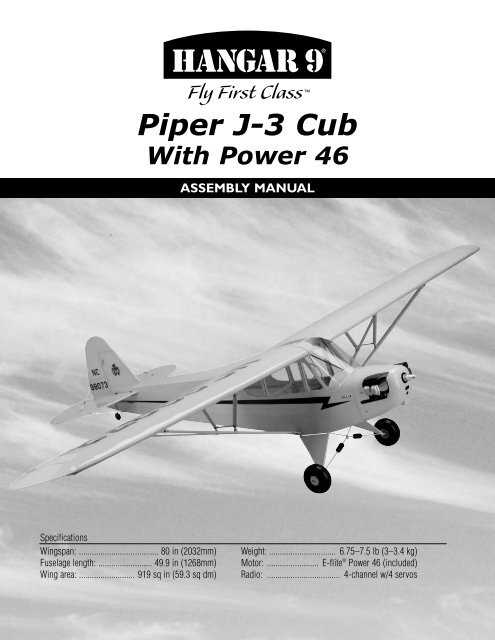
<strong>Piper</strong> J-3 <strong>Cub</strong>With Power 46Assembly manualSpecificationsWingspan: ..................................... 80 in (2032mm)Fuselage length: ......................... 49.9 in (1268mm)Wing area: .......................... 919 sq in (59.3 sq dm)Weight: ............................... 6.75–7.5 lb (3–3.4 kg)Motor: ........................ E-flite ® Power 46 (included)Radio: ................................... 4-channel w/4 servos
Table of ContentsContents of Kit . . . . . . . . . . . . . . . . . . . . . . . . . . . . . . . . . . . . . . . . . . . . . . . . . . . . . . . . . . . . . . . . . . . .3Additional Required Equipment. . . . . . . . . . . . . . . . . . . . . . . . . . . . . . . . . . . . . . . . . . . . . . . . . . . . . . . .3Covering Colors . . . . . . . . . . . . . . . . . . . . . . . . . . . . . . . . . . . . . . . . . . . . . . . . . . . . . . . . . . . . . . . . . . .3Additional Required Tools and Adhesives. . . . . . . . . . . . . . . . . . . . . . . . . . . . . . . . . . . . . . . . . . . . . . . .4Field Equipment Required. . . . . . . . . . . . . . . . . . . . . . . . . . . . . . . . . . . . . . . . . . . . . . . . . . . . . . . . . . . .4Date of Purchase Warranty Period . . . . . . . . . . . . . . . . . . . . . . . . . . . . . . . . . . . . . . . . . . . . . . . . . . . . .5Limited Warranty. . . . . . . . . . . . . . . . . . . . . . . . . . . . . . . . . . . . . . . . . . . . . . . . . . . . . . . . . . . . . . . . . . .5Damage Limits . . . . . . . . . . . . . . . . . . . . . . . . . . . . . . . . . . . . . . . . . . . . . . . . . . . . . . . . . . . . . . . . . . . .5Safety Precautions . . . . . . . . . . . . . . . . . . . . . . . . . . . . . . . . . . . . . . . . . . . . . . . . . . . . . . . . . . . . . . . . .5Questions, Assistance, and Repairs . . . . . . . . . . . . . . . . . . . . . . . . . . . . . . . . . . . . . . . . . . . . . . . . . . . .6Inspection or Repairs . . . . . . . . . . . . . . . . . . . . . . . . . . . . . . . . . . . . . . . . . . . . . . . . . . . . . . . . . . . . . . .6Warranty Inspection and Repairs. . . . . . . . . . . . . . . . . . . . . . . . . . . . . . . . . . . . . . . . . . . . . . . . . . . . . . .6Non-Warranty Repairs. . . . . . . . . . . . . . . . . . . . . . . . . . . . . . . . . . . . . . . . . . . . . . . . . . . . . . . . . . . . . . .6Safety, Precautions, and Warnings . . . . . . . . . . . . . . . . . . . . . . . . . . . . . . . . . . . . . . . . . . . . . . . . . . . . .7Before Starting Assembly . . . . . . . . . . . . . . . . . . . . . . . . . . . . . . . . . . . . . . . . . . . . . . . . . . . . . . . . . . . .7Using the Manual . . . . . . . . . . . . . . . . . . . . . . . . . . . . . . . . . . . . . . . . . . . . . . . . . . . . . . . . . . . . . . . . . .7Section 1: Hinge Installation. . . . . . . . . . . . . . . . . . . . . . . . . . . . . . . . . . . . . . . . . . . . . . . . . . . . . . . . . .8Section 2: Motor and Cowling Installation . . . . . . . . . . . . . . . . . . . . . . . . . . . . . . . . . . . . . . . . . . . . . .11Section 3: Servo Installation (Aileron) . . . . . . . . . . . . . . . . . . . . . . . . . . . . . . . . . . . . . . . . . . . . . . . . .15Section 4: Servo Installation (Fuselage) . . . . . . . . . . . . . . . . . . . . . . . . . . . . . . . . . . . . . . . . . . . . . . . .20Section 5: Window Installation . . . . . . . . . . . . . . . . . . . . . . . . . . . . . . . . . . . . . . . . . . . . . . . . . . . . . . .24Section 6: Landing Gear Installation . . . . . . . . . . . . . . . . . . . . . . . . . . . . . . . . . . . . . . . . . . . . . . . . . . .25Section 7: Installing the Stabilizer. . . . . . . . . . . . . . . . . . . . . . . . . . . . . . . . . . . . . . . . . . . . . . . . . . . . .26Section 8: Wing Installation . . . . . . . . . . . . . . . . . . . . . . . . . . . . . . . . . . . . . . . . . . . . . . . . . . . . . . . . .29Recommended CG . . . . . . . . . . . . . . . . . . . . . . . . . . . . . . . . . . . . . . . . . . . . . . . . . . . . . . . . . . . . . . . .32Control Throws . . . . . . . . . . . . . . . . . . . . . . . . . . . . . . . . . . . . . . . . . . . . . . . . . . . . . . . . . . . . . . . . . . .32Preflight . . . . . . . . . . . . . . . . . . . . . . . . . . . . . . . . . . . . . . . . . . . . . . . . . . . . . . . . . . . . . . . . . . . . . . . .332006 Official AMA National Model Aircraft Safety Code. . . . . . . . . . . . . . . . . . . . . . . . . . . . . . . . . . . .34
Contents of KitCAGEDLarge Parts:A. Fuselage HAN4531B. Wing HAN4001C. Cowling HAN4004D. Tail Set HAN4003E. Landing Gear HAN4005F. Wing Strut Set HAN4010G. Window Set HAN4008FBItems Not Shown:Battery DoorTail Wheel AssemblyDecal SetPushrod SetWheelsTop Fuselage HatchHAN4532HAN4007HAN4009HAN4011HAN4006HAN4012Additional Required EquipmentRadio Equipment• 4-channel radio system (minimum)• 4 standard servos(one elevator, one rudder, two aileron)• Receiver• Receiver battery• Switch harness• 12" Servo Extension (JRPA098) (2)• “Y” Harness (JRPA135)• Large Arms/Horns w/Screw (JRPA212)Recommended JR ® or JR SPORT Systems• XP9303• XP7202• XP6102• XS600Recommended Spektrum ® System• DX7Battery, Speed Control and Motor Accessories• Phoenix-60A Speed Control: Brushless (CSEPHX60)• 4200mAh 4S2P 14.8V Li-Po, 13GA(THP42004S2PPL)• Connectors for speed control and battery• Propeller• ChargerSpektrum DX7JR XP6102JR XP9303
Additional Required Tools and AdhesivesTools• Adjustable wrench• Crimping tool• Drill• Drill bit: 1/16", 5/64", 3/32"• Felt-tipped pen• Heat gun• Hobby knife• Hobby scissors• Petroleum jelly• Phillips screwdriver (small)• Phillips screwdriver (large)• Pliers• Rotary tool w/sanding drum• Ruler• Sandpaper• Soldering iron• Solder• String• Threadlock (PAAPT42)• T-pinsAdhesives• 30-minute Epoxy (HAN8002)• Thin CA (PAAPT08)• Medium CA (PAAPT02)• Canopy Glue (PAAPT56)Other Required Items• Epoxy brushes• Felt-tipped pen or pencil• Measuring device (e.g. ruler, tape measure)• Mixing sticks for epoxy• Paper towels• Petroleum jelly• Rubbing alcohol• Sanding bar• Covering Iron (HAN101)• Covering Glove (HAN150)• Sealing Iron Sock (HAN141)Covering Colors• <strong>Cub</strong> Yellow• BlackHANU884HANU874
Safety, Precautions, and WarningsThis model is controlled by a radio signal that is subject to interference from many sources outside your control. Thisinterference can cause momentary loss of control so it is advisable to always keep a safe distance in all directions aroundyour model, as this margin will help to avoid collisions or injury.• Always operate your model in an open area away from cars, traffic, or people.• Avoid operating your model in the street where injury or damage can occur.• Never operate the model into the street or populated areas for any reason.• Never operate your model with low transmitter batteries.• Carefully follow the directions and warnings for this and any optional support equipment (chargers, rechargeablebattery packs, etc.) that you use.• Keep all chemicals, small parts and anything electrical out of the reach of children.• Moisture causes damage to electronics. Avoid water exposure to all equipment not specifically designed and protectedfor this purpose.Before Starting AssemblyBefore beginning the assembly of the <strong>Piper</strong> <strong>Cub</strong> 40, remove each part from its bag for inspection. Closely inspectthe fuselage, wing panels, rudder, and stabilizer for damage. If you find any damaged or missing parts, contact theplace of purchase.If you find any wrinkles in the covering, use a heat gun or sealing iron to remove them. Use caution while working aroundareas where the colors overlap to prevent separating the colors.HAN101 – Sealing IronHAN141 – Sealing IronSockHAN100 – Heat GunHAN150 – Covering GloveUsing the ManualThis manual is divided into sections to help make assembly easier to understand, and to provide breaks between eachmajor section. In addition, check boxes have been placed next to each step to keep track of each step completed. Stepswith a single box () are performed once, while steps with two boxes ( ) indicate that the step will requirerepeating, such as for a right or left wing panel, two servos, etc. Remember to take your time and follow the directions.
Section 1: Hinge InstallationRequired Parts• Stabilizer• Elevator• Fuselage• Rudder• Wing• Aileron (R&L)• Tail gear wire • Hinge (17) Step 3Place the hinges in the stabilizer.Required Tools and Adhesives• Thin CA• T-pins• 30-minute epoxy • Petroleum jelly• Drill • Drill bit: 1/16", 3/32"• Hobby knife Step 1Locate three hinges. Place a T-pin in the center ofeach hinge. Step 4Slide the elevator and stabilizer together. Remove theT-pins. There should be a 1/64" gap between thestabilizer and elevator. Step 2Drill a 1/16" hole in both a stabilizer and elevator half inthe center of the hinge locations. Step 5Check that the tips of the stabilizer and elevator arealigned. Wick thin CA into each of the hinges.Note: Do not use accelerator in the hingingprocess. The CA must be allowed to soak intothe hinge naturally.
Section 1: Hinge Installation Step 6After the CA has cured, flex the surfaces several times tobreak in the hinges. Step 9Coat the tail gear wire near the bushing with petroleumjelly. Work the lubricant into the bearing to prevent epoxyfrom entering the bearing, gluing the bearing to the wire. Step 7Pull on both surfaces to make sure the hinges are secure.Hint: Use a heat gun to warm the petroleumjelly to allow it to flow into the bushing. Step 10Drill a 3/32" hole in the rudder 1 1 / 4" from the bottom. Step 8Repeat Steps 1 through 7 for the aileron hinges. Eachaileron will use four hinges. Center the ailerons and makesure they are not binding before gluing the hinges.
Section 1: Hinge Installation Step 11Cut a groove from the hole to the bottom of the rudder toallow clearance for the tail gear bearing. Step 13Cut a slot in the end of the fuselage to accept the tailgear bearing. Step 12Apply a thin layer of lubricant where the bearing willride in the rudder. Use 30-minute epoxy to glue the wireinto the rudder. Step 14Install three hinges into the rudder. Test fit the rudderto the fuselage, sliding the hinges and tail wheel bracketinto position. Step 15Use 30-minute epoxy to glue the tail gear bearing into thefuselage. Use thin CA for the hinges.10
Section 2: Motor and Cowling InstallationRequired Parts• Fuselage• Propeller• Propeller adapter • Cowling• #2 x 3/8" sheet metal screw (4)Required Tools and Adhesives• Phillips screwdriver (small)• Drill • Drill bit: 1/16", 5/64"• Soldering iron• Solder• Electronic speed control w/connectors Step 2Tin the ends of the wires on your speed control by usingthe iron to heat the bare wires. It is always a good idea toapply the iron to one sire of the wire and feed the solderfrom the opposite side to draw the solder into the wire.Note: Use a good quality solder and flux whensoldering electronic components. Check withan electronic store to purchase the appropriatecomponents for soldering if you don't havethese on hand.Important: Always make sure that what isunder your soldering iron is of no great value.Solder that drips can easily damage a surface.It is suggested to have an inexpensive piece ofplywood under your soldering area to preventdamage from dripped solder. Step 1Locate the connectors for your motor. Use pliers to holdthe connector. Heat the connector with the soldering ironand feed a small amount of solder into the connector. Step 3While the wire on the speed control is still warm, heat theconnector with the soldering iron. Slide the wire from thespeed control into the connector and leave it for a secondto make sure the solder has fully heated. Remove thesoldering iron and allow the wire/connector to cool beforemoving anything. After a minute or two, give the connectora light pull to make sure it is secure.Note: A drop of flux will make the solder"stick" better than just using the solder alone.11
Section 2: Motor and Cowling Installation Step 4Once all the connectors have been installed, use heatshrink tubing to insulate them. If not insulated, they couldshort and damage the speed controller. Step 7Use double-sided tape or sticky back hook and loop tosecure the speed control inside the fuselage. Make sure itcan't move around, and that the wires going to the motorare secure and won't interfere with the operation of themotor. Step 5Repeat Steps 1 through 4 to install a connector onto thebattery lead of the speed control that matches the one onyour battery. Step 6Remove the cowling and propeller from the fuselage. Plugthe motor leads from the motor to the speed control. Step 8Pass the hook and loop straps through the battery floor asshown.12
Section 2: Motor and Cowling Installation Step 9Use the hook and loop straps to secure the battery insidethe fuselage. Step 11Unplug the speed control from the battery and receiver atthis time. Install the battery hatch back onto the fuselage.Note: If you find the battery slides forward orbackward, simply apply a piece of hook andloop material on the battery floor and battery tokeep the battery in position. Step 12Replace the cowling back onto the fuselage and tighten thepropeller adapter to secure it to the motor shaft. Step 10Plug the speed control into the throttle channel of thereceiver. Move the throttle trim and stick to low throttle.Plug the speed control into the battery and checkthe operation of the motor. The motor should rotatecounterclockwise when viewed from the front of theaircraft. If the motor rotates the wrong direction, follow theinstructions provided with your speed control to correctthe rotation direction.13
Section 3: Servo Installation (Aileron)Required Parts• Wing (L&R)• Servo hatch (L&R)• #2 x 3/8" screw (8) • Control horn (2)• 2mm x 20mm screw (6) • Clevis (2)• Clevis retainer (2)• 4 3 / 4" pushrod wire (2)• Pushrod wire keeper (2) Step 2Install the recommended servo hardware (grommets andeyelets) supplied with the servo. Temporarily install a longhalf servo arm (JRPA212) onto the servo and positionthe servo onto the hatch so the servo arm is centered inthe notch. Once satisfied, mark the location for the servomounting blocks using a felt-tipped pen.Required Tools and Adhesives• Phillips screwdriver (small) • 30-minute epoxy• Felt-tipped pen• String• Drill • Drill bit: 1/16", 3/32"• Pliers• “Y” harness• 12" servo extension (2) • Hobby knife• Long Servo Arm (JRPA212) (2) Step 1Remove the covering from the servo opening in thebottom of the wing using a hobby knife. Select the correctservo hatch by checking the alignment for the servo armon the plate with the one on the wing. Step 3Locate the 3/8" x 3/4" x 3/4" servo mounting blocks.Use 30-minute epoxy to glue the blocks to the hatch. Letthe epoxy fully cure before proceeding to the next step.14
Section 3: Servo Installation (Aileron) Step 4Place the aileron servo between the mounting blocks anduse a felt-tipped pen to mark the location of the four servomounting screws. Note that the servo must not touch thehatch in order to isolate engine vibration. Step 6Connect a 12" Servo Lead Extension (JRPA098) to theservo lead. Secure the connectors by tying them ina knot using dental floss or by using a commerciallyavailable connector clamp to prevent the servo leads frombecoming disconnected.Note: Before mounting the servo,electronically center the servo using thetransmitter, then install the servo arm toavoid having to remove the servo and centerthe arm later. It may be necessary to slightlytrim one of the servo mounting blocks to clearthe servo wire.Note: It is always a good idea to securethe servo connector and servo extensiontogether to prevent the wires frombecoming unplugged. Step 5Remove the servo and use a 1/16" drill bit to pre-drillthe holes for the servo mounting screws marked in theprevious step. Use the screws supplied with the servo tomount it to the servo mounting blocks.15
Section 3: Servo Installation (Aileron) Step 7Tie a wheel collar onto a piece of string. Drop the wheelcollar into the wing from the root and retrieve it from theservo opening. Step 8Tie the string onto the servo extension. Gently pull theextension through the wing using the string. Untie thestring when the servo lead has been pulled through. Usetape to secure the servo lead to the wing to prevent it fromfalling back into the wing panel. Step 9Secure the hatch using four #2 x 3/8" screws.16
Section 3: Servo Installation (Aileron) Step 10Place a clevis retainer onto a clevis. Thread the clevisonto a 4 3 / 4" pushrod wire. Remove the backplatefrom a control horn, and then attach the clevis to thecontrol horn. Step 12Drill the locations marked in the previous step usinga 3/32" drill bit. Step 11Position the control horn on the aileron. Use thepushrod wire as a guide to align the horn to the servoarm. Position the horn so the holes align with the hingeline. Use a felt-tipped pen to mark the positions for thethree mounting bolts. Step 13Place a few drops of thin CA into each of the holes toharden the balsa. Attach the control horn using three2mm x 20mm screws and the control horn backplate.Align holes with hinge line17
Section 3: Servo Installation (Aileron) Step 14Plug in the aileron servo to the radio system. Center thetrims on the transmitter to center the aileron servo. Holdthe aileron in neutral. Use a felt-tipped pen to mark thepushrod wire where it crosses the servo arm. Step 15Bend the pushrod wire at the mark. Use a pushrod wirekeeper to secure the pushrod wire to the servo arm. Step 16Repeat Steps 1 though 15 for the remaining wing panel.18
Section 4: Servo Installation (Fuselage)Required Parts• Fuselage• Clevis• Clevis retainer• Control horn• Wing strut mount (2) • #4 x 3/8" screw (4)• 19 3 / 4" pushrod dowel • 6" pushrod wire• Pushrod wire (32”)• 2 1 / 8" heat shrink tubing (2)• 2mm x 12mm screw (3)• 7 1 / 4" pushrod wire (2)Required Tools and Adhesives• Phillips screwdriver • Hobby knife• Drill • Drill bit: 3/32", 5/64"• Heat gun• Medium CA• Thin CA• Felt-tipped pen Step 1Remove the covering for the wing strut mount. Theopening is located above the rear landing gear mount. Step 2Slide the wing strut mount into the opening. Secure themount using two #4 x 3/8" screws. Step 3Install the recommended servo hardware (grommets andeyelets) supplied with the servos into the throttle, rudder,and elevator servos. Step 4Use the hardware provided with the servos to mount themin the fuselage.19
Section 4: Servo Installation (Fuselage) Step 5Place a clevis retainer onto a clevis. Thread the clevisonto a 32" pushrod wire. Remove the backplate from acontrol horn, and then attach the clevis to the controlhorn. Slide the pushrod into the rudder pushrod tube inthe fuselage. Position the horn so the holes align with thehinge line. Use a felt-tipped pen to mark the positions forthe three mounting bolts. Step 6Drill the locations marked in the previous step usinga 3/32" drill bit. Place a few drops of thin CA intoeach of the holes to harden the balsa. Attach the controlhorn using three 2mm x 12mm screws and the controlhorn backplate. Step 7Plug in the rudder servo to the radio system. Center thetrims on the transmitter to center the rudder servo. Holdthe rudder in neutral. Use a felt-tipped pen to mark thepushrod wire where it crosses the servo arm.Align holes with hinge line20
Section 4: Servo Installation (Fuselage) Step 8Remove the pushrod wire from the fuselage and removethe clevis. Bend the pushrod wire at the mark. Slidethe pushrod back into the fuselage from the radiocompartment, and then put the clevis back onto thewire. Use a pushrod wire keeper to secure the pushrodwire to the servo arm. Step 10Cut a groove into the pushrod from the hole to the endof the pushrod. Repeat for the opposite side so you endup with two grooves. The elevator pushrod wires willrest in these grooves. Step 11Locate the two 7 1 / 4" pushrods. Make a bend in onepushrod 1/4" from the non-threaded end. The remainingpushrod is bent 1/2" from the non-threaded end. Step 9Locate the 19 3 / 4" wood pushrod for the elevator. Drill two5/64" holes through the dowel, 1" and 1 1 / 4" from one end.The holes must be parallel to each other. Step 12Test fit the two wires. The wire bent at 1/2" is placed inthe hole closest to the pushrod end. You will have totrim the wire down after the bend so it won’t interferewith the other pushrod. Once fit, use medium CA toglue the wires to the dowel.21
Section 4: Servo Installation (Fuselage) Step 13Slide the 2 1 / 8" piece of heat shrink over the wires anddowel. Use a heat gun or lighter to shrink the tubing. Oncethe tubing has been shrunk, apply thin CA to each end ofthe shrink to complete this part of the pushrod assembly. Step 16Plug the necessary servo leads into the receiver. Thisincludes the switch harness and battery leads as well.Use double-sided tape or hook and loop to secure thereceiver and battery inside the fuselage. Step 14Repeat Steps 9 through 13 for the opposite end ofthe dowel, but only drill one hole 1" from the end andprepare one 6" pushrod wire with a bend 1/4" from thenon-threaded end. Step 15Slide the elevator pushrod wire in position into thefuselage. It may take some time to get it in, so bepatient. Slide a clevis retainer onto two clevises, andthen thread them onto the pushrod wires at the aft endof the fuselage. This will prevent the pushrod wire fromfalling out of the fuselage.Note: There is a tube located under theelevator servo for the antenna wire. Route thewire through this tube to the tail of the aircraft. Step 17Mount the receiver switch to the side of the fuselage.22
Section 5: Window InstallationRequired Parts• Side window (L&R)• Support (2)• Front windscreen• Fuselage hatch Step 3Cut and fit the two supports to the fuselage. Use mediumCA to glue them into position.Required Tools and Adhesives• Hobby scissors• Canopy glue• Hobby knife Step 1Use hobby scissors and a hobby knife to trim the sidewindows from their sheets. Leave a 1/8" lip to glue thewindows to the fuselage. Step 4Test fit the front windscreen into position. Trim asnecessary. Use canopy glue to secure the frontwindscreen to the fuselage. Step 2Test fit the windows from the inside of the fuselage. Trimthem as necessary so they fit flush to the outside ofthe fuselage. Use canopy glue (PAAPT56) to secure thewindows into the fuselage. Install the window into thefuselage hatch at this time as well.Note: You can use epoxy as well, but bevery careful not to get epoxy on the nice clearwindows.23
Section 6: Landing Gear InstallationRequired Parts• Landing gear• 3.35" (85mm) wheel (2) • Wheel cap (2)• Inner wheel hub (2) • Outer wheel hub (2)• 1" (25mm) wheel • Landing gear strap (4)• 2mm x 14mm screw (8)• Large wheel collar w/setscrew (4)• 3mm x 10mm screw (8)• Small wheel collar w/setscrew Step 2Position the 3.35" (85mm) wheel onto the inner hub.Attach the outer wheel hub to the inner wheel hub usingfour 2mm x 14mm screws. The screws go through theouter wheel hub and into the inner wheel hub.Required Tools and Adhesives• Phillips screwdriver (small) • Hex wrench• Hobby knife• Sandpaper• Threadlock Step 1Use a hobby knife to scrape away the paint on the landinggear where the wheel will be located. Slide the inner wheelhub onto the axle. Next, slide a large wheel collar 3/8"from the end of the axle and secure it using the setscrew. Step 3Snap the wheel cap onto the wheel. Step 4Repeat Steps 1 through 3 for the remaining wheel.24
Section 6: Landing Gear Installation Step 5Position the landing gear to the bottom of the fuselage.Secure the position of the gear using four landing gearstraps and eight 3mm x 10mm screws. Step 6Secure the tail wheel using the small wheel collarand setscrew.Section 7: Installing the StabilizerRequired Parts• Stabilizer assembly • Fuselage• #4 washer (4) • #2 washer (3)• 2-56 x 1/2" screw (3) • 2-56 nut (3)• Clevis (4) • Clevis retainer (4)• Cable ends (4) • Brass crimps (8)• Cable• Pushrod wire keeper• Control horn (2)• 2mm x 12mm screw (6)• Brass fitting (small) (6)• Brass fitting (large) (2)• #2 x 1/2" sheet metal screw• 4-40 x 1/2" socket head screw (4) Step 1Slide the stabilizer halves into the slot in the fuselage.Use four 4-40 x 1/2" screws and four #4 washers tosecure the stabilizer. Use threadlock to prevent thescrews from vibrating loose during flight.Required Tools and Adhesives• Threadlock• Pliers• Drill • Drill bit: 3/32"• Adjustable wrench • Crimping tool• Phillips screwdriver (small) • Threadlock25
Section 7: Installing the Stabilizer Step 2Attach a control horn to one of the elevator clevises. Linethe holes in the control horn with the hinge line and markthe location for the mounting crews onto the elevator. Step 4Repeat Steps 2 and 3 for the remaining elevatorcontrol horn. Step 5Attach the elevator pushrod to the servo arm of theelevator servo using a pushrod wire keeper. Step 6Bend each of the fittings (small and large) to about a45-degree angle. Step 3Drill the holes using a 3/32" drill bit. Use thin CA toharden the holes. Mount the control horn using the hornbackplate and three 2mm x 12mm screws. Step 7Attach the large brass fittings at the bottom rear of thefuselage using the #2 x 1/2" sheet metal screw.26
Section 7: Installing the Stabilizer Step 8Attach the small brass fitting to the fin and stabilizerusing 2-56 x 1/2" screws, #2 washers and 2-56 nuts.Fittings are placed on both sides of the rudder andthe top and bottom of the stabilizer. Step 10Cut the cable into four equal pieces. Prepare one cable bysliding the cable through a crimp, through the cable end,then back through the crimp twice. Pull the excess cabletight and use a crimping tool to complete the job. Repeatfor all four of the ends. Step 9Slide a clevis retainer onto a clevis. Thread a cable endinto the clevis. Prepare four of these connectors.27
Section 7: Installing the Stabilizer Step 11Attach the four connectors to the brass fittingsof the stabilizer. Step 12Repeat Step 10, only passing the cable through the brassfittings instead of the cable ends. The cables should havevery light tension.Note: Be careful not to overtightencables as you may introduce a warp intothe tail surfaces.Section 8: Wing InstallationRequired Parts• Wing• Fuselage• 4-40 lock nut (16) • 4-40 nut (4)• Strut support anchor (4) • Strut bracket (4)• Strut end (4)• Strut (narrow) (L&R)• Strut (wide) (L&R) • Strut brace (long) 2• Strut brace (short) (2) • Strut cross brace (2)• #2 x 3/8" screw (4) • Fuselage hatch• 1/4-20 x 2" nylon bolt (2)• 4-40 x 1/2" socket head screw (24) Step 1Attach two strut brackets to the bottom of the wing usingfour 4-40 x 1/2" socket head screws. Use threadlock toprevent the screws from loosening during flight.Required Tools and Adhesives• Hex wrench• Adjustable wrench• Threadlock• Phillips screwdriver (small)28
Section 8: Wing Installation Step 2Thread the strut support anchors into the holes in thewing until the threads are no longer exposed. The anchorshave external threads.Note: The airfoil of the struts matches thedirection of the wing. The struts also havefittings in the center, which will face towardsthe wing when installed. Step 4Thread a 4-40 nut onto the threaded end of the strut.Thread a strut end onto the strut. The nut will be usedonce the strut has been adjusted. Step 3Attach the strut to the strut brackets using two 4-40 x 1/2"socket head screws and two 4-40 lock nuts. The wide strutgoes towards the leading edge, the narrow strut towardsthe trailing edge. Step 5Install the short strut brace to the rear strut supportanchor and the long strut brace to the front strut supportanchor using 4-40 x 1/2" socket head screws and4-40 nuts. Attach the strut supports and the strut crossbrace using two 4-40 x 1/2" socket head screws andtwo 4-40 lock nuts.Leading Edge of Strut29
Section 8: Wing Installation Step 6Slide the wing tube into the wing panel. Slide the tube andpanel into position on the fuselage. Step 8Support the fuselage so the wing is not resting on thework surface. Adjust the strut end so it aligns with thewing strut mount. Attach the wing struts using two4-40 x 1/2" socket head bolts and two 4-40 lockingnuts. Once attached, tighten the 4-40 nuts on the strut toprevent the end from rotating when the wing is removedfor storage. Step 7Secure the wing panel using a 1/4-20 x 2" nylon bolt. Step 9Repeat Steps 1 through 8 to install the remaining wingpanel and strut. Step 10Install the fuselage hatch using four #2 x 3/8" screws.Note: The struts on the J-3 <strong>Cub</strong> arefunctional, so be sure all bolts and nutsare tight before flying. Failure to do socould result in wing failure.Note: When removing the wing, simplydisconnect the bolts holding the strut to thefuselage. This will make things much easierwhen installing the wing at the field.30
Control ThrowsThe amount of control throw should be adjusted as closelyas possible using mechanical means, rather than makinglarge changes electronically at the radio. By movingthe position of the clevis at the control horn toward theoutermost hole, you will decrease the amount of controlthrow of the control surface. Moving it toward the controlsurface will increase the amount of throw. Moving thepushrod wire at the servo arm will have the oppositeeffect: Moving it closer to center will decrease throw,and away from center will increase throw. Work with acombination of the two to achieve the closest or exactcontrol throws listed.ElevatorLow RateHigh Rate11/16" (11.5º) Up 9/16" (10º) Down1 1 / 4" (19.5º) Up 1" (18º) DownAileronLow RateHigh RateRudder1/2" (9º) Up 3/8" (8º) Down1 1 / 16" (22º) Up 7/8" (21º) DownLinear measurement (inches) measured at root.1 1 / 2" (28º) Left 1 1 / 2" (28º) RightLinear measurement (inches) measured at frontof counterbalance.Linear measurement (inches) measured atwidest part of elevator (roughly in the center).Note: Use the Low Rate for most flying. TheHigh Rate is used specifically for performingspin maneuvers.31
Recommended CGAn important part of preparing the aircraft for flight isproperly balancing the model. This is especially importantwhen various engines are mounted.Caution: Do not inadvertently skip this step!The recommended Center of Gravity (CG) range for the<strong>Piper</strong> J-3 <strong>Cub</strong> is 3 1 / 4" (82.5mm) behind the leading edgeof the wing against the fuselage. It is suggested to start atthe forward end of the range until comfortable with theflight characteristics of your aircraft. If necessary, movethe battery pack or add weight to either the nose or thetail until the correct balance is achieved. Stick-onweights are available at your local hobby shop and workwell for this purpose.PreflightRange Test Your Radio Step 1Before going to the field, be sure that your batteriesare fully charged, per the instructions included withyour radio. Charge both the transmitter and receiverpack for your airplane. Use the recommended chargersupplied with your particular radio system, following theinstructions provided with the radio. In most cases theradio should be charged the night before going out flying. Step 2Before each flying session, be sure to range check yourradio. See your radio manual for the recommendedrange and instructions for your radio system. Each radiomanufacturer specifies different procedures for theirradio systems. Next, start the engine. With the modelsecurely anchored, check the range again. The range testshould not be significantly affected. If it is, don’t attemptto fly! Have your radio equipment checked out by themanufacturer. Step 3Double-check that all controls (aileron, elevator, rudderand throttle) move in the correct direction. Step 4Check the radio installation and make sure all the controlsurfaces are moving correctly (i.e. the correct directionand with the recommended throws). Test the motor tomake sure the speed control is operating properly.Check all the control horns, servo horns, and clevises tomake sure they are secure and in good condition. Replaceany items that would be considered questionable. Failureof any of these components in flight would mean the lossof your aircraft.Note: Keep loose items that can get entangledin the propeller away from the prop. Theseincluded loose clothing, or other objects suchas pencils and screwdrivers. Especially keepyour hands away from the propeller.32
Notes:
2007 Official AMANational Model Aircraft Safety CodeGENERAL1) I will not fly my model aircraft in sanctionedevents, air shows or model flying demonstrations untilit has been proven to be airworthy by having beenpreviously, successfully flight tested.2) I will not fly my model higher than approximately400 feet within 3 miles of an airport without notifyingthe airport operator. I will give right-of-way and avoidflying in the proximity of full-scale aircraft. Wherenecessary, an observer shall be utilized to superviseflying to avoid having models fly in the proximity offull-scale aircraft.3) Where established, I will abide by the safety rulesfor the flying site I use, and I will not willfully anddeliberately fly my models in a careless, reckless and/or dangerous manner.4) The maximum takeoff weight of a model is 55pounds, except models flown under ExperimentalAircraft rules.5) I will not fly my model unless it is identified withmy name and address or AMA number, on or in themodel. (This does not apply to models while beingflown indoors.)6) I will not operate models with metal-bladedpropellers or with gaseous boosts, in which gasesother than air enter their internal combustionengine(s); nor will I operate models with extremelyhazardous fuels such as those containingtetranitromethane or hydrazine.7) I will not operate models with pyrotechnics (anydevice that explodes, burns, or propels a projectileof any kind) including, but not limited to, rockets,explosive bombs dropped from models, smokebombs, all explosive gases (such as hydrogen-filledballoons), or ground mounted devices launching aprojectile. The only exceptions permitted are rocketsflown in accordance with the National Model RocketrySafety Code or those permanently attached (as perJATO use); also those items authorized for Air ShowTeam use as defined by AST Advisory Committee(document available from AMA HQ). In any case,models using rocket motors as a primary means ofpropulsion are limited to a maximum weight of 3.3pounds and a G series motor. (A model aircraft isdefined as an aircraft with or without engine, not ableto carry a human being.)8) I will not consume alcoholic beverages prior to,nor during, participation in any model operations.9) Children under 6 years old are only allowedon the flight line as a pilot or while receivingflight instruction.RADIO CONTROL1) I will have completed a successful radio equipmentground range check before the first flight of a new orrepaired model.2) I will not fly my model aircraft in the presenceof spectators until I become a qualified flier, unlessassisted by an experienced helper.3) At all flying sites a straight or curved line(s) mustbe established in front of which all flying takes placewith the other side for spectators. Only personnelinvolved with flying the aircraft are allowed at or inthe front of the flight line. Intentional flying behind theflight line is prohibited.4) I will operate my model using only radio controlfrequencies currently allowed by the FederalCommunications Commission. (Only properlylicensed Amateurs are authorized to operateequipment on Amateur Band frequencies.)34
2007 Official AMANational Model Aircraft Safety Code5) Flying sites separated by three miles or moreare considered safe from site-to site interference,even when both sites use the same frequencies. Anycircumstances under three miles separation requirea frequency management arrangement, which maybe either an allocation of specific frequencies foreach site or testing to determine that freedom frominterference exists. Allocation plans or interferencetest reports shall be signed by the parties involvedand provided to AMA Headquarters. Documents ofagreement and reports may exist between (1) twoor more AMA Chartered Clubs, (2) AMA clubs andindividual AMA members not associated with AMAClubs, or (3) two or more individual AMA members.6) For Combat, distance between combat engagementline and spectator line will be 500 feet per cubicinch of engine displacement. (Example: .40 engine= 200 feet.); electric motors will be based onequivalent combustion engine size. Additional safetyrequirements will be per the RC Combat section of thecurrent Competition Regulations.7) At air shows or model flying demonstrations, asingle straight line must be established, one side ofwhich is for flying, with the other side for spectators.8) With the exception of events flown under AMACompetition rules, after launch, except for pilots orhelpers being used, no powered model may be flowncloser than 25 feet to any person.9) Under no circumstances may a pilot or otherperson touch a powered model in flight.Organized RC Racing Event10) An RC racing event, whether or not an AMA RuleBook event, is one in which model aircraft competein flight over a prescribed course with the objective offinishing the course faster to determine the winner.A. In every organized racing event in which contestants,callers and officials are on the course:1. All officials, callers and contestants must properlywear helmets, which are OSHA, DOT, ANSI, SNELL orNOCSAE approved or comparable standard while onthe racecourse.2. All officials will be off the course except for thestarter and their assistant.3. "On the course” is defined to mean any areabeyond the pilot/staging area where actual flyingtakes place.B. I will not fly my model aircraft in any organizedracing event which does not comply with paragraph Aabove or which allows models over 20 pounds unlessthat competition event is AMA sanctioned.C. Distance from the pylon to the nearest spectator(line) will be in accordance with the currentCompetition Regulations under the RC Pylon Racingsection for the specific event pending two or threepylon course layout.11) RC night flying is limited to low-performancemodels (less than 100 mph). The models must beequipped with a lighting system that clearly definesthe aircraft’s attitude at all times.35
9892© 2007 Horizon Hobby, Inc.4105 Fieldstone RoadChampaign, Illinois 61822(877) 504-0233horizonhobby.com


