


You also want an ePaper? Increase the reach of your titles
YUMPU automatically turns print PDFs into web optimized ePapers that Google loves.
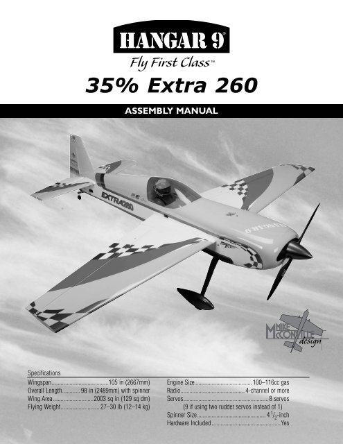
<strong>35%</strong> <strong>Extra</strong> <strong>260</strong>Assembly manualSpecificationsWingspan......................................105 in (2667mm)Overall Length............ 98 in (2489mm) with spinnerWing Area............................2003 sq in (129 sq dm)Flying Weight.......................... 27–30 lb (12–14 kg)Engine Size.......................................100–116cc gasRadio........................................... 4-channel or moreServos.........................................................8 servos(9 if using two rudder servos instead of 1)Spinner Size.............................................. 4 1 / 2-inchHardware Included...............................................Yes
Table of ContentsUsing the <strong>Manual</strong> ..................................................................3Required Tools and Adhesives ........................................................3UltraCote Covering Colors ...........................................................3Before Starting Assembly ............................................................3Radio and Power Systems Requirements ................................................4Recommended JR, JR SPORT and Spektrum Systems ......................................4Recommended Engine Setup .........................................................4FS One ..........................................................................4Warranty Period ...................................................................5Limited Warranty. ..................................................................5Damage Limits ....................................................................5Safety Precautions .................................................................5Questions, Assistance, and Repairs ....................................................6Inspection or Repairs ...............................................................6Warranty Inspection and Repairs.......................................................6Non-Warranty Repairs...............................................................6Safety, Precautions, and Warnings .....................................................7Contents of Kit ....................................................................7Aileron Servo Installation ............................................................8Elevator Servo Installation ..........................................................12Rudder and Rudder Servo Installation..................................................13Landing Gear Installation ...........................................................16Stabilizer Installation...............................................................19Engine Installation (DA100) .........................................................21Engine Installation (Evolution 116GX) .................................................26Receiver Installation ...............................................................30Pilot and Canopy Installation ........................................................32Radio Setup .....................................................................33Control Throws ...................................................................34Computer Radio Enhancements ......................................................34Recommended Center of Gravity (CG) .................................................35Rates and Expos ..................................................................35Preflight ........................................................................36Range Test Your Radio .............................................................37Instructions for Disposal of WEEE by Users in the European Union...........................372007 Official AMA National Model Aircraft Safety Code................................ 38–392
Radio and Power Systems Requirements• 7-channel computer radio system (minimum) w/receiver • Large Servo Arms (JRPA236) (8 pkgs)• 24-Inch Servo Lead Extension (JRPA102) (5) • JR Charge Jack Switch (JRPA004) (3)• 36-inch Servo Lead Extension (JRPA103) (3)• Choke Ring (JRPA029) (For throttle servo lead)• JR 8611A or 8711 Metal Geared high torque servos (7) or equivalentCaution: Only metal-geared servos of 180 oz in torque or greater should be used on the control surfaces.• 2700mAh or larger for receiver (2) (A minimum of 3000mAh is required when using super high-torque servos)• 1500mAh or larger for ignition (4.8 or 6.0V for DA-100, 3-cell Li-Po for Evolution ® 116cc))The elevator installation will require:Two servos and mixing through the radioOrTwo servos and a JR® MatchBox (JPA0900)Recommended JR, JR SPORT and Spektrum Systems• JR 10X• JR XP9303• JR X9303 2.4• JR XP7202• Spektrum DX-7JR XP9303Recommended Engine SetupSpektrum DX7JR 10XDA-100• In cowl mufflersor• MTW 75 canisters with headers• 27 x 10 propellerEvolution 116• In cowl mufflersor• MTW 75 canisters with headers• 28 x 10 propellerFS OneWith FS One ® you get more than photorealistic fields, gorgeousskies and realistic-looking aircraft. You get incredibly advancedaerodynamic modeling that simulates every possible aspectof real-world flight.4HANS2000
Warranty PeriodExclusive Warranty- Horizon Hobby, Inc., (Horizon) warranties that the Products purchased (the "Product") will be freefrom defects in materials and workmanship at the date of purchase by the Purchaser.Limited Warranty(a) This warranty is limited to the original Purchaser ("Purchaser") and is not transferable. REPAIR OR REPLACEMENTAS PROVIDED UNDER THIS WARRANTY IS THE EXCLUSIVE REMEDY OF THE PURCHASER. This warranty covers onlythose Products purchased from an authorized Horizon dealer. Third party transactions are not covered by this warranty.Proof of purchase is required for warranty claims. Further, Horizon reserves the right to change or modify this warrantywithout notice and disclaims all other warranties, express or implied.(b) Limitations- HORIZON MAKES NO WARRANTY OR REPRESENTATION, EXPRESS OR IMPLIED, ABOUT NON-INFRINGEMENT, MERCHANTABILITY OR FITNESS FOR A PARTICULAR PURPOSE OF THE PRODUCT. THEPURCHASER ACKNOWLEDGES THAT THEY ALONE HAVE DETERMINED THAT THE PRODUCT WILL SUITABLY MEETTHE REQUIREMENTS OF THE PURCHASER’S INTENDED USE.(c) Purchaser Remedy- Horizon's sole obligation hereunder shall be that Horizon will, at its option, (i) repair or (ii)replace, any Product determined by Horizon to be defective. In the event of a defect, these are the Purchaser's exclusiveremedies. Horizon reserves the right to inspect any and all equipment involved in a warranty claim. Repair or replacementdecisions are at the sole discretion of Horizon. This warranty does not cover cosmetic damage or damage due to acts ofGod, accident, misuse, abuse, negligence, commercial use, or modification of or to any part of the Product. This warrantydoes not cover damage due to improper installation, operation, maintenance, or attempted repair by anyone other thanHorizon. Return of any goods by Purchaser must be approved in writing by Horizon before shipment.Damage LimitsHORIZON SHALL NOT BE LIABLE FOR SPECIAL, INDIRECT OR CONSEQUENTIAL DAMAGES, LOSS OF PROFITS ORPRODUCTION OR COMMERCIAL LOSS IN ANY WAY CONNECTED WITH THE PRODUCT, WHETHER SUCH CLAIMIS BASED IN CONTRACT, WARRANTY, NEGLIGENCE, OR STRICT LIABILITY. Further, in no event shall the liability ofHorizon exceed the individual price of the Product on which liability is asserted. As Horizon has no control over use,setup, final assembly, modification or misuse, no liability shall be assumed nor accepted for any resulting damage orinjury. By the act of use, setup or assembly, the user accepts all resulting liability.If you as the Purchaser or user are not prepared to accept the liability associated with the use of this Product, you areadvised to return this Product immediately in new and unused condition to the place of purchase.Law: These Terms are governed by Illinois law (without regard to conflict of law principals).Safety PrecautionsThis is a sophisticated hobby Product and not a toy. It must be operated with caution and common sense and requiressome basic mechanical ability. Failure to operate this Product in a safe and responsible manner could result in injuryor damage to the Product or other property. This Product is not intended for use by children without direct adultsupervision. The Product manual contains instructions for safety, operation and maintenance. It is essential to readand follow all the instructions and warnings in the manual, prior to assembly, setup or use, in order to operate correctlyand avoid damage or injury.5
Questions, Assistance, and RepairsYour local hobby store and/or place of purchase cannot provide warranty support or repair. Once assembly, setup oruse of the Product has been started, you must contact Horizon directly. This will enable Horizon to better answer yourquestions and service you in the event that you may need any assistance. For questions or assistance, please direct youremail to productsupport@horizonhobby.com, or call 877.504.0233 toll free to speak to a service technician.Inspection or RepairsIf this Product needs to be inspected or repaired, please call for a Return Merchandise Authorization (RMA). Packthe Product securely using a shipping carton. Please note that original boxes may be included, but are not designedto withstand the rigors of shipping without additional protection. Ship via a carrier that provides tracking and insurancefor lost or damaged parcels, as Horizon is not responsible for merchandise until it arrives and is acceptedat our facility. A Service Repair Request is available at www.horizonhobby.com on the “Support” tab. If you do nothave internet access, please include a letter with your complete name, street address, email address and phone numberwhere you can be reached during business days, your RMA number, a list of the included items, method of paymentfor any non-warranty expenses and a brief summary of the problem. Your original sales receipt must also be includedfor warranty consideration. Be sure your name, address, and RMA number are clearly written on the outside of theshipping carton.Warranty Inspection and RepairsTo receive warranty service, you must include your original sales receipt verifying the proof-of-purchasedate. Provided warranty conditions have been met, your Product will be repaired or replaced free of charge. Repair orreplacement decisions are at the sole discretion of Horizon Hobby.Non-Warranty RepairsShould your repair not be covered by warranty the repair will be completed and payment will berequired without notification or estimate of the expense unless the expense exceeds 50% of the retailpurchase cost. By submitting the item for repair you are agreeing to payment of the repair without notification. Repairestimates are available upon request. You must include this request with your repair. Non-warranty repair estimates willbe billed a minimum of ½ hour of labor. In addition you will be billed for return freight. Please advise us of your preferredmethod of payment. Horizon accepts money orders and cashiers checks, as well as Visa, MasterCard, American Express,and Discover cards. If you choose to pay by credit card, please include your credit card number and expiration date. Anyrepair left unpaid or unclaimed after 90 days will be considered abandoned and will be disposed of accordingly. Pleasenote: non-warranty repair is only available on electronics and model engines.Electronics and engines requiring inspection or repair should be shipped to the following address:Horizon Service Center4105 Fieldstone RoadChampaign, Illinois 61822All other Products requiring warranty inspection or repair should be shipped to the following address:Horizon Product Support4105 Fieldstone RoadChampaign, Illinois 61822Please call 877-504-0233 with any questions or concerns regarding this product or warranty.6
Safety, Precautions, and WarningsThis model is controlled by a radio signal that is subject to interference from many sources outside your control. Thisinterference can cause momentary loss of control so it is advisable to always keep a safe distance in all directions aroundyour model, as this margin will help to avoid collisions or injury.• Always operate your model in an open area away from cars, traffic, or people.• Avoid operating your model in the street where injury or damage can occur.• Never operate the model into the street or populated areas for any reason.• Never operate your model with low transmitter batteries.• Carefully follow the directions and warnings for this and any optional support equipment (chargers, rechargeablebattery packs, etc.) that you use.• Keep all chemicals, small parts and anything electrical out of the reach of children.• Moisture causes damage to electronics. Avoid water exposure to all equipment not specifically designed and protectedfor this purpose.Contents of KitReplacement PartsA. HAN1001 Fuselage w/HatchB. HAN1002 Right Wing Panel w/AileronC. HAN1003 Left Wing Panel w/AileronD. HAN1004 Right Stabilizer w/ElevatorE. HAN1005 Left Stabilizer w/ElevatorF. HAN1006 Anodized Wing TubeG. HAN1007 Anodized Stabilizer TubeH. HAN1008 RudderI. HAN1009 CanopyJ. HAN1010 Canopy HatchK. HAN1011 Fiberglass Painted CowlL. HAN1012 Landing GearM. HAN1014 Painted Wheel PantsN. HAN331 Tailwheel AssemblyO. HAN1015 Hardware KitP. HAN360 Painted Pilot HelmetNot ShownHAN1013Decal SetKJIAHDCEGBNFPLMO7
Aileron Servo InstallationRequired Parts• Wing panel (left and right)• Ball end w/hardware (4) • Control horn (4)• 3-inch (76mm) linkage (4) Step 3Tip the wing so the root is facing down and lower theweight through the wing.Required Tools and Adhesives• JR ® MatchBox (2) • Phillips screwdriver• Ruler• Nut driver: 1/4-inch• Hex wrench: 3/32-inch • String w/weight• Servo extension, 24-inch (610mm) (2)• 1 1 / 2-inch Single Side Alum Adj.Spline Servo Arm (4) Step 1Secure a 24-inch (610mm) servo extension to theoutboard aileron servo. Step 4Tie the string to the servo extension. Step 2Tie a weight to a piece of string. Lower the weight into theopening for the outboard aileron servo.8
Step 5Use the string to pull the extension through the wing. Tapethe extension so it will not fall back into the wing. Step 7Thread the control horn onto the control horn screw so thebottom of the horn is 1 inch (25mm) from the surface ofthe aileron. Step 6Secure the servo using the hardware provided with theservo. The output of the servo faces the trailing edge. Step 8Install the inboard aileron servo and the control horn.Thread the control horn so it is 13/16-inch (21mm) fromthe aileron surface as shown. Step 9Plug both aileron servos into the receiver. Center theaileron trim and stick to center the aileron servos. Alsomake sure any sub-trims have been set to zero in the radiomemory. Check the operation of the servos at this time.9
Step 10Attach the ball end to the bottom side of the servoarm using the ball end hardware. The hole used will be1 1 / 4-inch (32mm) from the center of the servo arm. Step 12Assemble and install the 3-inch (76mm) linkage for theoutboard aileron servo ONLY at this time. Adjust thelinkage to center the aileron and attach the linkage to thehorn with the setscrew. Remember to keep the servo armparallel to the hinge line while adjusting the linkage. Step 11With the servo at the neutral position and radio on, attachthe servo arm to the servo. Place it on the spline that setsthe arm closest to parallel with the hinge line. (This willbe fine tuned later.) Turn off the receiver and manually turnthe arm so it is parallel with the hinge line. Step 13Plug the aileron servos into a JR MatchBox. The outboardservo plugs into Port 1 and the inboard servo plugs intoPort 2. The MatchBox is used to link the two servos tooperate properly. Plug the MatchBox into the aileronchannel of your receiver. Step 14With only the outboard aileron linkage attached to thecontrol horn, turn on the radio and adjust the sub-trim inthe transmitter until the aileron is at the neutral position.Deflect the stick to full right aileron and adjust the traveladjust so the deflection is 34.4 degrees. Repeat this forfull left deflection and adjust for 33 degrees.10
Step 15Turn the dial on the MatchBox to position 2. Step 18Repeat for full left aileron. Step 16Use the MatchBox to adjust the center position of theinboard servo, aligning the servo arm parallel to the hingeline. Assemble and install the 3-inch (76mm) linkagefor the outboard aileron servo, but do not attach it to thecontrol horn at this time. Confirm that the hole in the ballend is perfectly aligned with the hole in the control horn. Step 19BEFORE turning off the power to the receiver, turn the dialon the MatchBox back to the 0 position to save the data. Step 17Deflect the aileron stick to full right and check thealignment of the hole in the ball end with the hole in thecontrol horn. If they are misaligned (likely), adjust thetravel of the servo with the MatchBox while holding fullright stick, until the holes align perfectly. Step 20Recheck to be sure the neutral and full deflection ineach direction are correct and the holes are aligned inall 3 positions BEFORE securing the ball end to thecontrol horn. Step 21Install the screw to secure the ball end to the control horn. Step 22Repeat steps 1 through 21 for the remaining wing panel,only plug the matchbox into the auxiliary channel that isbeing mixed to the aileron channel for this wing panel.11
Elevator Servo InstallationRequired Parts• Ball end w/hardware (2) • Control horn (2)• Stabilizer/elevator (left and right)• 3-inch (76mm) linkage (2)Required Tools and Adhesives• Hex wrench: 3/32-inch• Nut driver: 1/4-inch• 1 1 / 2-inch Single Side Alum Adj. Spline Servo Arm(2) Step 3Assemble the linkage for the elevator using a ball end,control horn and a 3-inch (76mm) linkage. Thread thehorn onto the screw so the bottom of the horn is 3/4-inch(19mm) from the surface of the elevator. Step 1Install the elevator servo into the stabilizer. Make sure topull the servo lead through the opening toward the leadingedge before placing the servo. Step 4Attach the ball end to the servo horn using the hardwareprovided with the ball end. The attachment point will be1 1 / 2-inch (38mm) from the center of the servo horn. Step 2Install the servo arm onto the elevator servo. Use the radiosystem to center the servo beforehand. Step 5Repeat Steps 1 through 4 for the remaining elevator servoand linkage.12
Rudder and Rudder Servo InstallationRequired Parts• Ball end w/hardware (2) • Control horn (2)• Rudder• Fuselage• Removable hinge pin • Tiller arm• Tail gear assembly • Steering spring (2)• #6 x 5/8-inch socket head sheet metal screws (4)• 4 1 / 2-inch (114mm) linkage Step 2Assemble the rudder linkage using a 4 1 / 2-inch (114mm)linkage, ball end and control horn. The control horn isthen threaded on the control horn screw so the bottom ofthe horn is 5/8-inch (16mm) from the control surface.Required Tools and Adhesives• Thin CA• Drill• Drill bit: 3/32-inch (2.5mm)• Hex wrench: 3/32-inch• Nut driver: 1/4-inch• 1 1 / 2-inch Single Side Alum Adj. Spline Servo ArmNote: When using a servo with less than300 oz/in of torque, it is highly recommendedto use two rudder servos and link themtogether using a JR MatchBox. An additionalservo location on the opposite side of thefuselage will require the removal of thecovering to install your second servo. Step 3Attach the rudder to the fin/fuselage using the hinge pinlocated in the hinges. Step 1Secure a 24-inch (610mm) servo extension to the rudderservo. Mount the servo in the fuselage as shown.Hint: Use a drill to aid in installingthe hinge wire. This will help guide thewire through each of the hinges.13
Step 4Attach the ball end to the servo horn using the hardwareprovided with the ball end. The attachment point will be1 1 / 2-inch (38mm) from the center of the servo horn. Step 6Drill each of the locations using a drill and 3/32-inch(2.5mm) drill bit. Step 5Position the tail gear assembly on the bottom of thefuselage. Use a felt-tipped pen to mark the locations forthe two screws. Step 7Thread a #6 x 5/8-inch socket head sheet metal screw intothe holes, then remove the screw.Note: The tail gear will keep the rudderhinge in position. You will need to trim theremovable hinge pin so it is 1/4-inch (4mm)above the tail gear when it has been installed.14
Step 8Apply a few drops of thin CA into each of the two holes toharden the wood. This will help in preventing the screwsfrom vibrating loose. Step 10Attach the tail gear assembly to the bottom of the fuselageusing two #6 x 5/8-inch socket head sheet metal screws. Step 9Follow Steps 5 through 8 to attach the tiller arm to thebottom of the rudder with two #6 x 5/8-inch socket headsheet metal screws. Step 11Complete the rudder installation by connecting the tailwheel to the tiller arm with two steering springs.15
Landing Gear InstallationRequired Parts• Fuselage assembly • Main landing gear• #8 washer (4) • 8-32 locknut (4)• Axle w/nut (2) • #4 washer (4)• 4-40 blind nut (4)• 4 1 / 2-inch (114mm) wheel (2)• 4-40 x 1/2-inch socket head screw (4)• 5/32-inch wheel collar w/setscrews (4) Step 2Secure the axle to the main landing gear.Required Tools and Adhesives• Threadlock• Drill• Drill bit: 9/64-inch (3.5mm)• Hex wrench: .050-inch, 3/32-inch Step 1Attach the landing gear to the fuselage using four8-32 x 3/4-inch socket head screws, four #8 washersand four 8-32 lock nuts. Step 3Use a file to create a flat on the axle for the setscrews inthe collars to tighten onto. This will help in preventingthem from loosening in flight.16
Step 3Attach the wheel to the axle using two 5/32-inch wheelcollars. The collars are placed on either side of the wheel. Step 5Mark the location for the two screws through the landinggear and onto the wheel pant using a felt-tipped pen.Note: Always use threadlock onmetal-to-metal fasteners to preventthem from vibrating loose. Step 6Drill the locations marked in the previous step using adrill and 9/64-inch (3.5mm) drill bit. Step 4Place the fuselage on a level surface. Slide the wheel pantinto position. The pant must be positioned so it will notcome in contact with the surface.17
Step 7Use pliers to install the two 4-40 blind nuts in the wheelpant as shown. Step 8Secure the wheel pant to the landing gear using two4-40 x 1/2-inch socket head screws and two #4 washers.Note: Always use threadlock onmetal-to-metal fasteners to preventthem from vibrating loose.18
Stabilizer InstallationRequired Parts• Fuselage assembly • Stabilizer/elevator (2)• Stabilizer tube • #4 washer (4)• 4-40 x 1/2-inch socket head screw(4) Step 3Secure a 24-inch (610mm) servo extension to the elevatorservo lead. Pass the extension into the fuselage, then slidethe tube into the fuselage.Required Tools and Adhesives• Threadlock• Hobby knife• Hex wrench: 3/32-inch • Tap handle• 4-40 tap• Drill• Drill bit: 1/16-inch (1.5mm), 1/8-inch (3mm) Step 1Slide the stabilizer tube into one of the stabilizer halves. Step 4Use a 4-40 x 1/2-inch socket head screw and #4 washerto secure the position of the stabilizer. Step 2Use a hobby knife to remove the covering from theopening in the fuselage for the servo lead.Note: Always use threadlock onmetal-to-metal fasteners to preventthem from vibrating loose. Step 5Repeat Steps 2 through 4 for the remaining stabilizer.19
Step 6Drill a pilot hole in the stabilizer tube using a drill and1/16-inch (1.5mm) drill bit. Step 8Secure the position of the tube using a 4-40 x 1/2-inchsocket head screw and #4 washer. The screw will threadinto a blind nut that is installed inside the stabilizer. Step 7Remove the stabilizer tube and use a drill and 1/8-inch(3mm) drill bit to drill a hole in the stabilizer tube. Step 9Repeat Steps 6 through 8 for the remaining stabtube screw.20
Engine Installation (DA100)Required Parts• Fuselage assemblyRequired Tools and Adhesives• Threadlock Step 3Use a drill and 5/16-inch (8mm) drill bit to drill the holesin the firewall for mounting the engine.Note: For simplicity the DA will be shownwith canister installation and the Evolutionwith Muffler installation. Either enginecan be used with either exhaust option. Step 1Collect the items shown for the installation of yourparticular engine. Step 4Install the 1/4-20 blind nuts from the back side of thefirewall. You can use the bolts and standoffs to pull theblind nuts into position. Step 5Install engine using four 2 7 / 8-inch (73mm) machinedaluminum standoffs and four 1/4-20 x 3 3 / 4-inch sockethead bolts and four 1/4-inch lock washers. Step 2Measure mark and drill firewall to correct dimensions andoffset to the left side.21
Step 6Use a hobby knife to trim the covering from the openingon the bottom of the fuselage. Leave enough materialthat you can use the covering to seal the opening with acovering iron. Step 7Install silicone tubes (8 total) in each of the two canistermounts.22
Step 8Install throttle servo and attach the linkage (supplied) witha 4-40 ball link on each end. Step 9Slide the canister mufflers into model and attach theheaders to the engine.23
Step 10Secure the ignition module to the engine box. Makethe connections between the ignition box and engineat this time. Step 11Install the switch for the ignition at the front of thefuselage as shown. Step 12Secure the battery for the ignition inside the fuselageusing a hook and loop strap. Make sure to add a fewpieces of foam between the fuselage and battery to preventdamage to the battery caused by vibration. Connect thebattery to the ignition switch. Step 13Attach the fuel line from the fuel tank to the carburetor.Mak sure the line is from the clunk and not the vent line.24
Step 14Cut the line between the carburetor and fuel tank to installa Fuel Dot (HAN115). This will make fueling the tankmuch easier when the cowl is installed. Step 17Make a circular opening under the carb in the cowling sothe choke butterfly can be manually operated. Step 15Route the vent line from the fuel tank out the bottomof the cowl. Step 16Make any necessary cutouts to clear the enginecomponents in the cowl. Remove a section from thebottom of the cowling near the mufflers for coolingoutlet as shown. This opening is necessary to allowcooling air to pass through the cowling to preventoverheating of your engine.25
Engine Installation (Evolution 116GX)Required Parts• Fuselage assemblyRequired Tools and Adhesives• Threadlock Step 3Install the tapered aluminum adapter plate to the right sideof the engine with a short 1/4-20 bolt and AC nut throughthe top mounting hole and don't tighten yet. Step 1Collect the items shown for the installation of yourparticular engine. Step 4Measure, mark and drill firewall to correct dimensions andoffset to the left side. Step 2Install the short aluminum adapter to the top left mountinghole on the engine using the short 1/4-20 bolt and aircraftnut. Don't tighten yet.26
Step 3Use a drill and 5/16-inch (8mm) drill bit to drill the holesin the firewall for mounting the engine. Step 7Cut the top of the motor box to mount the throttle servo asphotos and install it top down. Step 5Install the 1/4-20 blind nuts from the back side of thefirewall. You can use the bolts and standoffs to pull theblind nuts into position. Step 6Install engine using four 2 7 / 8-inch (73mm) machinedaluminum standoffs, one 3/16-inch (5mm) aluminumspacers and four 1/4-20 x 4-inch socket head bolts andfour 1/4-inch lock washers. Step 8Drill a hole in the firewall for the throttle linkage to pass.27
Step 9Install the (supplied) throttle linkage. Step 12Use 30-minute epoxy to glue in cover plate to the fuselagefor pipe tunnel. Step 10Attach the fuel line from the fuel tank to the carburetor.Make sure the line is from the clunk and not the vent line.Cut the line between the carburetor and fuel tank to installa Fuel Dot (HAN115). This will make fueling the tankmuch easier when the cowl is installed. Step 11Secure the battery for the ignition inside the fuselageusing a hook and loop strap. Make sure to add a fewpieces of foam between the fuselage and battery to preventdamage to the battery caused by vibration. Connect thebattery to the ignition switch. The EVO 116 requires a3-cell Li-Po ignition battery. Step 13Bolt the mufflers onto engine using the hardware providedwith the mufflers.28
Step 14Make any necessary cutouts to clear the enginecomponents in the cowl. Remove a section from thebottom of the cowling near the mufflers for coolingoutlet as shown. This opening is necessary to allowcooling air to pass through the cowling to preventoverheating of your engine. Step 15Route the vent line from the fuel tank out the bottomof the cowl.29
Receiver InstallationRequired Parts• Fuselage assembly• Hook and loop strap (4)Required Tools and Adhesives• Threadlock• Hobby knife• Receiver• Switch harness• 1/4-inch (6mm) foam) • Receiver battery• Ignition battery• 24-Inch Servo Lead Extension (JSP98040) (3)• 36-inch Servo Lead Extension (JSP98050) (3)IMPORTANT: Two receiverbatteries of at least 2700mAh orlarger are needed. Two 4000 2S2PLi-Po receiver packs are shown. Step 1Install both receiver batteries with two layers of padded2-sided servo tape and then secure in place with thesupplied hook and loop straps.30
Step 4Use a hobby knife to remove the covering from the holesin the sides of the fuselage for the two radio switches. Step 7Secure any switches to the fuselage using the hardwareprovided with the switches. Step 10Put foam rubber or thick padded 2-sided tape under thereceiver. Use a hook and loop strap to secure the receiverto the cross brace inside the fuselage. Plug the servosinto the receiver and route the servo leads neatly along theside of the fuselage. Route the antenna wire (if necessary)at this time as well.31
Pilot and Canopy InstallationRequired Parts• Fuselage assembly• Canopy• Pilot bust Step 3Trim the instrument panel from the decal sheet. Apply thedecal in position in the cockpit.Required Tools and Adhesives• Canopy glue• Felt-tipped pen• Painter's tape• Waxed paper• 30-minute epoxy • Sandpaper• Rubbing alcohol • Paper towel Step 4Position the canopy onto the hatch. Use a felt-tipped pento trace the outline of the canopy onto the hatch. Step 1Be sure the visor screws are tight. It is recommended toremove the screws and use a drop of threadlock on themto prevent vibrations from causing them to vibrate loose. Step 5Sand the hatch and canopy where they contact each otherusing sandpaper. Clean the area using rubbing alcoholand a paper towel. Step 2Use 30-minute epoxy to secure the pilot bust to thecanopy hatch.32
Step 6Slip a piece of waxed paper between the hatch andfuselage. Use canopy glue to attach the canopy to thecanopy hatch. Use painter's tape to keep the canopy inposition until the glue fully cures.Radio SetupA 7-channel or greater computer radio is highlyrecommended. This allows the following features:• Mixing the right aileron to the left aileron (flaperon mix)• Electronically adjustable aileron differential• Mixing the right elevator to the left elevator (dualelevator mixing)• Independent travel and trim adjustments for eachelevator halfWhen using a 7-Channel or greater computer radio,each servo is plugged into its own separate channel.Consult your radio manual for specific details onhookup and programming.33
Control ThrowsSetting the control throws for your <strong>Extra</strong> <strong>260</strong> does requiresome attention to detail. To correctly set the throws, itis highly suggested to use the following procedure toachieve the greatest mechanical advantage from yourservos. Step 1Determine the maximum amount of control surface throwfrom the throws listed. Use the high rate throws listedto set the maximum amount of throw, then use yourcomputer radio for the lower rate listed. Step 2Set the Travel Adjust (ATV on a Futaba transmitter) toabout 15% under the max. (On a JR transmitter, thatis 1<strong>35%</strong>.) Make sure to set both directions during thisprocess. Step 3Adjust the position of the clevis on the control horn andposition of the ball link on the servo arm to achieve thethrow decided in Step 1. It is highly recommended not tochange the position on the servo arm unless absolutelynecessary. Use Travel Adjust (ATV) to finalize the throws.That is why we left a little margin in the percentages backin Step 2. Step 4If setting a dual elevator or aileron, match the linkagelocations used back in Step 3. Increase or decrease theTravel Adjust (ATV) a few points as necessary to fine-tunethe throws to match up left and right sides and up anddown throws so all is symmetrical.This is all necessary to tune the mechanical advantage asgood as possible. When setting up a model for 3D, themechanical advantage will be less because of the largethrows, and thus the servo will work harder and wearfaster. Using an insufficient servo for the job, or tryingto get too much throw, will cause something to give,probably the servo.There isn’t an exact geometry to the linkage, as it dependson how much throw each individual modeler requires.The linkage geometry should always be maximized so theservo isn’t working any harder than it has to.Aileron:High Rate: 34.4 Degrees up, 54% Exponential33 Degrees down, 54% ExponentialLow Rate: 23 Degrees up, 40% Exponential22 Degrees down, 40% ExponentialElevator:High Rate: 48.5 Degrees up, 75% Exponential47 Degrees down, 75% ExponentialLow Rate: 13 Degrees up, 45% Exponential13 Degrees down, 45% ExponentialRudder:High Rate: 44 Degrees right, 50% Exponential44 Degrees left, 50% ExponentialLow Rate: 30 Degrees right, 50% Exponential30 Degrees left, 50% ExponentialComputer Radio EnhancementsA computer radio will allow you to do quite a bit offine-tuning to the feel of the <strong>Extra</strong> <strong>260</strong>, which will makeaerobatics even easier.34
Rates and ExposUse Expo to soften the feel of the model. On high 3Drates, use quite a bit of expo. The goal on 3D rates is toget the model to feel the same around neutral as it doeson low rates.Use low rate settings for all flying except for 3Daerobatics. For precision flying or general sport hotdogging,the low rate throws are perfect, even for snaprolls. The only exception is rudder rates. Use 3D rudderrate when doing stall turns and rolling circles, sincethe more rudder the better for these. When doing 3Daerobatics, flip to 3D rates just before the maneuver. Assoon as the maneuver is done, flip back down to low rateto avoid over-controlling the model.Recommended Center of Gravity (CG)An important part of preparing the aircraft for flight isproperly balancing the model. This is especially importantwhen various engines are mounted.Caution: Do not inadvertently skip this step!The recommended Center of Gravity (CG) location foryour model is: 3 1 / 2to 4 inches (89 to 102mm) backfrom leading edge of wing at the wing tip. Mark thelocation of the CG onto the bottom of the wing usinga felt-tipped pen. With a helper, lift the aircraft with yourindex finger at the location marked on the wing. Makesure the aircraft is upright when checking the CG. If thenose of your aircraft hangs low, add weight to the rear ofthe aircraft. If the tail hangs low, add weight to the noseof the aircraft. Stick-on weights are available at your localhobby store and work well for this purpose.35
PreflightFor those of you who are veterans of large models, thisis old news. But to you newcomers to the world of largemodels, this is very important information.While many smaller models are not critical of properbattery use, and are tolerant of improper control linkagesetups and flying techniques, large models are not. Don’tlet that scare you away from large models; they are trulyone of the best flying experiences in RC that moneycan buy. However, please pay particular attention to thefollowing areas.Maintain the proper mechanical advantage on allcontrol surface linkages.Just as with unsealed hinge gaps, mechanical advantageis often another cause of flutter. Please follow the controlhorn and servo arm lengths recommended in this manual.Shorter arms on the servo or longer control horns on theelevator and ailerons are fine, but do not try to go theother way to increase throw. It can cause flutter or servofailure on the <strong>Extra</strong> <strong>260</strong>. The recommended linkage setupsare more than adequate to achieve full 3D throws.Check the radio installation and make sure all thecontrol surfaces are moving correctly (i.e. the correctdirection and with the recommended throws). Testrun the engine and make sure it transitions smoothlyfrom idle to full throttle and back. Also ensure theengine is tuned according to the manufacturer’sinstructions, and it will run consistently and constantlyat full throttle when adjusted.Check all the control horns, servo horns, and clevises tomake sure they are secure and in good condition. Replaceany items that would be considered questionable. Failureof any of these components in flight would mean the lossof your aircraft.While many smaller models are very tolerant of impropercontrol linkage setups and flying techniques, large modelsare not. Don’t let that scare you away from large models;they are truly one of the best flying experiences in RC thatmoney can buy. However, please pay particular attention tothe following areas.Never attempt to make full throttle dives!Large models perform much more like full-size aircraftthan small models. If the airframe goes too fast, such asin a high throttle dive, it may fail. The <strong>Extra</strong> <strong>260</strong> should beflown like a full-scale <strong>Extra</strong> <strong>260</strong>. Throttle management isabsolutely necessary.Hardware checksDouble-check the setscrews in all contol horns to be surethey are very tight. Periodically check these to be surethey have not loosened over time. Always use threadlockon metal-to-metal fasteners.Receiver Battery SelectionBe sure adequate batteries are used to power the receiver.It is STRONGLY recommended that two identical 6-voltreceiver packs are used. Each pack must have a minimumof 2700mAh capacity. Use packs of 3000mAh when superhigh torque servos are used.Servo selectionBe sure all servos used on elevator, aileron and rudder aremetal geared type and have at least 188 oz in of torque.Failure to do this will very likely result in a failure andloss of the model.Range checkAlways range check the radio system per themanufacturer's instructions before the initial test flight andperiodically afterward.Check the voltage of the on-board packsALWAYS use an ESV with a 1-amp load to check thereceiver battery packs and the ignition pack before eachand every flight. If there is any doubt that the packs arequestionable, DO NOT FLY until the packs are recharged.36
Instructions for Disposal of WEEE byUsers in the European UnionThis product must not be disposed of with other waste.Instead, it is the user’s responsibility to dispose of theirwaste equipment by handing it over to a designatedcollection point for the recycling of waste electricaland electronic equipment. The separate collection andrecycling of your waste equipment at the time of disposalwill help to conserve natural resources and ensure that itis recycled in a manner that protects human health andthe environment. For more information about where youcan drop off your waste equipment for recycling, pleasecontact your local city office, your household wastedisposal service or where you purchased the product.37
2007 Official AMANational Model Aircraft Safety CodeGENERAL1. A model aircraft shall be defined as a non-humancarryingdevice capable of sustained flight in theatmosphere. It shall not exceed limitations establishedin this code and is intended to be used exclusively forrecreational or competition activity.2. The maximum takeoff weight of a model aircraft,including fuel, is 55 pounds, except for those flownunder the AMA Experimental Aircraft Rules.3. I will abide by this Safety Code and all rulesestablished for the flying site I use. I will not willfullyfly my model aircraft in a reckless and/or dangerousmanner.4. I will not fly my model aircraft in sanctioned events,air shows, or model demonstrations until it has beenproven airworthy.5. I will not fly my model aircraft higher thanapproximately 400 feet above ground level, whenwithin three (3) miles of an airport without notifying theairport operator. I will yield the right-of-way and avoidflying in the proximity of full-scale aircraft, utilizing aspotter when appropriate.6. I will not fly my model aircraft unless it is identifiedwith my name and address, or AMA number, inside oraffixed to the outside of the model aircraft. This doesnot apply to model aircraft flown indoors.7. I will not operate model aircraft with metal-bladepropellers or with gaseous boosts (other than air),nor will I operate model aircraft with fuels containingtetranitromethane or hydrazine.8. I will not operate model aircraft carrying pyrotechnicdevices which explode burn, or propel a projectileof any kind. Exceptions include Free Flight fuses ordevices that burn producing smoke and are securelyattached to the model aircraft during flight. Rocketmotors up to a G-series size may be used, providedthey remain firmly attached to the model aircraft duringflight. Model rockets may be flown in accordance withthe National Model Rocketry Safety Code; however,they may not be launched from model aircraft. Officiallydesignated AMAAir Show Teams (AST) are authorizedto use devices and practices as defined within the AirShow Advisory Committee Document.9. I will not operate my model aircraft while under theinfluence of alcohol or within eight (8) hours of havingconsumed alcohol.10. I will not operate my model aircraft while using anydrug which could adversely affect my ability to safelycontrol my model aircraft.11. Children under six (6) years old are only allowed ona flightline or in a flight area as a pilot or while underflight instruction.12. When and where required by rule, helmets must beproperly worn and fastened. They must be OSHA, DOT,ANSI, SNELL or NOCSAE approved or comply withcomparable standards.38
2007 Official AMANational Model Aircraft Safety CodeRadio Control1. All model flying shall be conducted in a manner toavoid over flight of unprotected people.2. I will have completed a successful radio equipmentground-range check before the first flight of a new orrepaired model aircraft.3. I will not fly my model aircraft in the presence ofspectators until I become a proficient flier, unless I amassisted by an experienced pilot.4. At all flying sites a line must be established, in front ofwhich all flying takes place. Only personnel associatedwith flying the model aircraft are allowed at or in frontof the line. In the case of airshows demonstrationsstraight line must be established. An area away fromthe line must be maintained for spectators. Intentionalflying behind the line is prohibited.5. I will operate my model aircraft using only radiocontrolfrequencies currently allowed by the FederalCommunications Commission (FCC). Only individualsproperly licensed by the FCC are authorized to operateequipment on Amateur Band frequencies.6. I will not knowingly operate my model aircraft withinthree (3) miles of any preexisting flying site withouta frequency-management agreement. A frequencymanagementagreement may be an allocation offrequencies for each site, a day-use agreement betweensites, or testing which determines that no interferenceexists. A frequency-management agreement may existbetween two or more AMA chartered clubs, AMAclubs and individual AMA members, or individualAMA members. Frequency-management agreements,including an interference test report if the agreementindicates no interference exists, will be signed by allparties and copies provided to AMA Headquarters.7. With the exception of events flown under official AMArules, no powered model may be flown outdoors closerthan 25 feet to any individual, except for the pilot andlocated at the flight line.8. Under no circumstances may a pilot or other persontouch a model aircraft in flight while it is still underpower, except to divert it from striking an individual.9. Radio-controlled night flying is limited to lowperformancemodel aircraft (less than 100 mph).The model aircraft must be equipped with a lightingsystem which clearly defines the aircraft's attitude anddirection at all times.10. The operator of a radio-controlled model aircraft shallcontrol it during the entire flight, maintaining visualcontact without enhancement other than by correctivelenses that are prescribed for the pilot. No modelaircraft shall be equipped with devices which allow itto be flown to a selected location which is beyond thevisual range of the pilot.39
10492.1© 2007 Horizon Hobby, Inc.4105 Fieldstone RoadChampaign, Illinois 61822(877) 504-0233horizonhobby.com


