Circuit Switching and Packet Switching.
Circuit Switching and Packet Switching.
Circuit Switching and Packet Switching.
- No tags were found...

You also want an ePaper? Increase the reach of your titles
YUMPU automatically turns print PDFs into web optimized ePapers that Google loves.
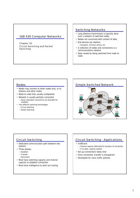
168 430 Computer NetworksChapter 10<strong>Circuit</strong> <strong>Switching</strong> <strong>and</strong> <strong>Packet</strong><strong>Switching</strong><strong>Switching</strong> Networks• Long distance transmission is typically doneover a network of switched nodes• Nodes not concerned with content of data• End devices are stations—Computer, terminal, phone, etc.• A collection of nodes <strong>and</strong> connections is acommunications network• Data routed by being switched from node tonodeNodes• Nodes may connect to other nodes only, or tostations <strong>and</strong> other nodes• Node to node links usually multiplexed• Network is usually partially connected—Some redundant connections are desirable forreliability• Two different switching technologies—<strong>Circuit</strong> switching—<strong>Packet</strong> switchingSimple Switched Network<strong>Circuit</strong> <strong>Switching</strong>• Dedicated communication path between twostations• Three phases—Establish—Transfer—Disconnect• Must have switching capacity <strong>and</strong> channelcapacity to establish connection• Must have intelligence to work out routing<strong>Circuit</strong> <strong>Switching</strong> - Applications• Inefficient—Channel capacity dedicated for duration of connection—If no data, capacity wasted• Set up (connection) takes time• Once connected, transfer is transparent• Developed for voice traffic (phone)1
Public <strong>Circuit</strong> SwitchedNetworkTelecomms Components• Subscriber— Devices attached to network• Subscriber line— Local Loop— Subscriber loop— Connection to network— Few km up to few tens of km• Exchange— <strong>Switching</strong> centers— End office - supports subscribers• Trunks— Branches between exchanges— Multiplexed<strong>Circuit</strong> Establishment<strong>Circuit</strong> Switch Elements<strong>Circuit</strong> <strong>Switching</strong> Concepts• Digital Switch—Provide transparent signal path between devices• Network Interface• Control Unit—Establish connections• Generally on dem<strong>and</strong>• H<strong>and</strong>le <strong>and</strong> acknowledge requests• Determine if destination is free• construct path—Maintain connection—DisconnectBlocking or Non-blocking• Blocking—A network is unable to connect stations because allpaths are in use—A blocking network allows this—Used on voice systems• Short duration calls• Non-blocking—Permits all stations to connect (in pairs) at once—Used for some data connections2
Space Division <strong>Switching</strong>• Developed for analog environment• Separate physical paths• Crossbar switch—Number of crosspoints grows as square of number ofstations—Loss of crosspoint prevents connection—Inefficient use of crosspoints• All stations connected, only a few crosspoints in use—Non-blockingSpace Division SwitchMultistage Switch• Reduced number of crosspoints• More than one path through network—Increased reliability• More complex control• May be blockingThree Stage Space DivisionSwitchTime Division <strong>Switching</strong>• Modern digital systems rely on intelligent controlof space <strong>and</strong> time division elements• Use digital time division techniques to set up<strong>and</strong> maintain virtual circuits• Partition low speed bit stream into pieces thatshare higher speed streamControl Signaling Functions• Audible communication with subscriber• Transmission of dialed number• Call can not be completed indication• Call ended indication• Signal to ring phone• Billing info• Equipment <strong>and</strong> trunk status info• Diagnostic info• Control of specialist equipment3
Control Signal Sequence• Both phones on hook• Subscriber lifts receiver (off hook)• End office switch signaled• Switch responds with dial tone• Caller dials number• If target not busy, send ringer signal to targetsubscriber• Feedback to caller— Ringing tone, engaged tone, unobtainable• Target accepts call by lifting receiver• Switch terminates ringing signal <strong>and</strong> ringing tone• Switch establishes connection• Connection release when Source subscriber hangs upSwitch to Switch Signaling• Subscribers connected to different switches• Originating switch seizes interswitch trunk• Send off hook signal on trunk, requesting digitregister at target switch (for address)• Terminating switch sends off hook followed byon hook (wink) to show register ready• Originating switch sends addressLocation of Signaling• Subscriber to network—Depends on subscriber device <strong>and</strong> switch• Within network—Management of subscriber calls <strong>and</strong> network—more complexIn Channel Signaling• Use same channel for signaling <strong>and</strong> call— Requires no additional transmission facilities• Inb<strong>and</strong>— Uses same frequencies as voice signal— Can go anywhere a voice signal can— Impossible to set up a call on a faulty speech path• Out of b<strong>and</strong>— Voice signals do not use full 4kHz b<strong>and</strong>width— Narrow signal b<strong>and</strong> within 4kHz used for control— Can be sent whether or not voice signals are present— Need extra electronics— Slower signal rate (narrow b<strong>and</strong>width)Drawbacks of In ChannelSignaling• Limited transfer rate• Delay between entering address (dialing) <strong>and</strong>connection• Overcome by use of common channel signalingCommon Channel Signaling• Control signals carried over paths independent of voicechannel• One control signal channel can carry signals for anumber of subscriber channels• Common control channel for these subscriber lines• Associated Mode— Common channel closely tracks interswitch trunks• Disassociated Mode— Additional nodes (signal transfer points)— Effectively two separate networks4
Common v. In ChannelSignalingCommonChannelSignalingModesSignaling System Number 7• SS7• Common channel signaling scheme• ISDN• Optimized for 64k digital channel network• Call control, remote control, management <strong>and</strong>maintenance• Reliable means of transfer of info in sequence• Will operate over analog <strong>and</strong> below 64k• Point to point terrestrial <strong>and</strong> satellite linksSS7Signaling Network Elements• Signaling point (SP)—Any point in the network capable of h<strong>and</strong>ling SS7control message• Signal transfer point (STP)—A signaling point capable of routing control messages• Control plane—Responsible for establishing <strong>and</strong> managingconnections• Information plane—Once a connection is set up, info is transferred in theinformation planeTransferPointsSignaling Network Structures• STP capacities—Number of signaling links that can be h<strong>and</strong>led—Message transfer time—Throughput capacity• Network performance—Number of SPs—Signaling delays• Availability <strong>and</strong> reliability—Ability of network to provide services in the face ofSTP failures5
Softswitch Architecture• General purpose computer running software to make it a smartphone switch• Lower costs• Greater functionality— <strong>Packet</strong>izing of digitized voice data— Allowing voice over IP• Most complex part of telephone network switch is softwarecontrolling call process— Call routing— Call processing logic— Typically running on proprietary processor• Separate call processing from hardware function of switch• Physical switching done by media gateway• Call processing done by media gateway controllerTraditional <strong>Circuit</strong> <strong>Switching</strong>Softswitch<strong>Packet</strong> <strong>Switching</strong> Principles• <strong>Circuit</strong> switching designed for voice—Resources dedicated to a particular call—Much of the time a data connection is idle—Data rate is fixed• Both ends must operate at the same rateBasic Operation• Data transmitted in small packets—Typically 1000 octets (bytes)—Longer messages split into series of packets—Each packet contains a portion of user data plussome control info• Control info—Routing (addressing) info• <strong>Packet</strong>s are received, stored briefly (buffered)<strong>and</strong> past on to the next node—Store <strong>and</strong> forwardUse of <strong>Packet</strong>s6
Advantages• Line efficiency— Single node to node link can be shared by many packets overtime— <strong>Packet</strong>s queued <strong>and</strong> transmitted as fast as possible• Data rate conversion— Each station connects to the local node at its own speed— Nodes buffer data if required to equalize rates• <strong>Packet</strong>s are accepted even when network is busy— Delivery may slow down• Priorities can be used<strong>Switching</strong> Technique• Station breaks long message into packets• <strong>Packet</strong>s sent one at a time to the network• <strong>Packet</strong>s h<strong>and</strong>led in two ways—Datagram—Virtual circuitDatagram• Each packet treated independently• <strong>Packet</strong>s can take any practical route• <strong>Packet</strong>s may arrive out of order• <strong>Packet</strong>s may go missing• Up to receiver to re-order packets <strong>and</strong> recoverfrom missing packetsDatagramDiagramVirtual <strong>Circuit</strong>• Preplanned route established before anypackets sent• Call request <strong>and</strong> call accept packets establishconnection (h<strong>and</strong>shake)• Each packet contains a virtual circuit identifierinstead of destination address• No routing decisions required for each packet• Clear request to drop circuit• Not a dedicated pathVirtual<strong>Circuit</strong>Diagram7
Virtual <strong>Circuit</strong>s v Datagram• Virtual circuits—Network can provide sequencing <strong>and</strong> error control—<strong>Packet</strong>s are forwarded more quickly• No routing decisions to make—Less reliable• Loss of a node looses all circuits through that node• Datagram—No call setup phase• Better if few packets—More flexible• Routing can be used to avoid congested parts of thenetwork<strong>Packet</strong> Size<strong>Circuit</strong> v <strong>Packet</strong> <strong>Switching</strong>• Performance—Propagation delay—Transmission time—Node delayEvent TimingX.25• 1976• Interface between host <strong>and</strong> packet switchednetwork• Almost universal on packet switched networks<strong>and</strong> packet switching in ISDN• Defines three layers—Physical—Link—<strong>Packet</strong>X.25 - Physical• Interface between attached station <strong>and</strong> link tonode• Data terminal equipment DTE (user equipment)• Data circuit terminating equipment DCE (node)• Uses physical layer specification X.21• Reliable transfer across physical link• Sequence of frames8
X.25 - Link• Link Access Protocol Balanced (LAPB)—Subset of HDLC—see chapter 7X.25 - <strong>Packet</strong>• External virtual circuits• Logical connections (virtual circuits) betweensubscribersX.25 Use of Virtual <strong>Circuit</strong>s Virtual <strong>Circuit</strong> Service• Logical connection between two stations—External virtual circuit• Specific preplanned route through network—Internal virtual circuit• Typically one to one relationship betweenexternal <strong>and</strong> internal virtual circuits• Can employ X.25 with datagram style network• External virtual circuits require logical channel—All data considered part of streamX.25 Levels• User data passes to X.25 level 3• X.25 appends control information—Header—Identifies virtual circuit—Provides sequence numbers for flow <strong>and</strong> error control• X.25 packet passed down to LAPB entity• LAPB appends further control informationUser Data <strong>and</strong> X.25 ProtocolControl Information9
Frame Relay• Designed to be more efficient than X.25• Developed before ATM• Larger installed base than ATM• ATM now of more interest on high speednetworksFrame Relay Background - X.25• Call control packets, in b<strong>and</strong> signaling• Multiplexing of virtual circuits at layer 3• Layer 2 <strong>and</strong> 3 include flow <strong>and</strong> error control• Considerable overhead• Not appropriate for modern digital systems withhigh reliabilityFrame Relay - Differences• Call control carried in separate logicalconnection• Multiplexing <strong>and</strong> switching at layer 2—Eliminates one layer of processing• No hop by hop error or flow control• End to end flow <strong>and</strong> error control (if used) aredone by higher layer• Single user data frame sent from source todestination <strong>and</strong> ACK (from higher layer) sentbackAdvantages <strong>and</strong> Disadvantages• Lost link by link error <strong>and</strong> flow control—Increased reliability makes this less of a problem• Streamlined communications process—Lower delay—Higher throughput• ITU-T recommend frame relay above 2MbpsProtocol ArchitectureControl Plane• Between subscriber <strong>and</strong> network• Separate logical channel used—Similar to common channel signaling for circuitswitching services• Data link layer—LAPD (Q.921)—Reliable data link control—Error <strong>and</strong> flow control—Between user (TE) <strong>and</strong> network (NT)—Used for exchange of Q.933 control signal messages10
User Plane• End to end functionality• Transfer of info between ends• LAPF (Link Access Procedure for Frame ModeBearer Services) Q.922—Frame delimiting, alignment <strong>and</strong> transparency—Frame mux <strong>and</strong> demux using addressing field—Ensure frame is integral number of octets (zero bitinsertion/extraction)—Ensure frame is neither too long nor short—Detection of transmission errors—Congestion control functionsUser Data Transfer• One frame type—User data—No control frame• No inb<strong>and</strong> signaling• No sequence numbers—No flow nor error controlRequired Reading• Stallings Chapter 10• ITU-T web site• Telephone company web sites (not muchtechnical info - mostly marketing)• X.25 info from ITU-T web site• Frame Relay forum11