MicroBrick I/O - Industrial Control Links
MicroBrick I/O - Industrial Control Links
MicroBrick I/O - Industrial Control Links

Create successful ePaper yourself
Turn your PDF publications into a flip-book with our unique Google optimized e-Paper software.
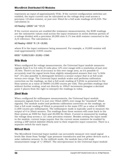
<strong>MicroBrick</strong> Distributed I/O Modulesrepresents an input of approximately 5Vdc. If the current configuration switches areenabled, the input current can be calculated as the voltage drop read across aprecision 121ohm resistor, or just over 40mA for a full scale readings of 65,535. Thecalculation is:A/D Reading = (65535 * mA * 121) /5If the current sources are enabled (for resistance measurements), the RAW readingsare the ratiometric values read across the input resistance in series (bottom portion ofa voltage divider) with a precision 20,000 ohm 0.1% low-drift resistor connected to theA/D reference. The calculation is:A/D Reading = 65535 * R / ( R + 20,000)where R is the input resistance being measured. For example, a 10,000 resistor willread approximately 21845 counts:65535 * 10,000/(10,000 + 20,000) = 218455Vdc ModeWhen configured for voltage measurements, the Universal Input module measuressignals from 0 to 5.6 volts (5 volts plus 12% over-range) with a resolution of just over16-bits. There’s no loss of accuracy in this over-range area, so it’s possible toaccurately read the signal levels from slightly misadjusted sensors that run “a littlehot”. It’s also possible to distinguish between a sensor output that is at full scaleversus over-range. The Universal Input module scales and performs calibrationcorrection on the readings, so that a full scale reading of 5.6Vdc is presented to theHost system as a value of 56000 (10,000 counts per volt). This provides readings thatwithout further scaling, read out directly in 100uV increments (imagine a decimalpoint 4 places from the right to interpret the readings in volts).20mA ModeWhen configured for milliampere measurements, the Universal Input modulemeasures signals from 0 to just over 40mA (200% over-range for “standard” 20mAsignals). The module scales and performs calibration correction on the readings, sothat a full scale reading of 40mA is presented to the main CPU as a value of 40000(1,000 counts per milliampere). The milliampere mode is typically used to measure theoutput of 4 to 20mA sensors. The readings from these sensors will come back to theHost system as 4000 for 4mA and 20,000 for 20mA. Current is measured by readingthe voltage drop across a 121 ohm precision resistor. Besides setting the input modein the module, current loops require that the current sense resistors be enabled bysetting a DIP switch (labeled 20mA) next to their respective input connector. There is aseparate switch for each input.Millivolt ModeThe <strong>MicroBrick</strong> Universal Input module can accurately measure very small signallevels like those from “bridge” type pressure transducers and low power devices such asolar radiation sensors. In the millivolt mode, the module has a full scalemeasurement range of +/-300mV. The microprocessor in the Universal Input module50Copyright © 2007 <strong>Industrial</strong> <strong>Control</strong> <strong>Links</strong>, Inc. All Right Reserved