Reducing Redundancies in Reconfigurable Antenna ... - IEEE Xplore
Reducing Redundancies in Reconfigurable Antenna ... - IEEE Xplore
Reducing Redundancies in Reconfigurable Antenna ... - IEEE Xplore

You also want an ePaper? Increase the reach of your titles
YUMPU automatically turns print PDFs into web optimized ePapers that Google loves.
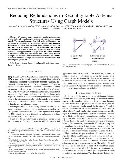
<strong>IEEE</strong> TRANSACTIONS ON ANTENNAS AND PROPAGATION, VOL. 59, NO. 3, MARCH 2011 793<strong>Reduc<strong>in</strong>g</strong> <strong>Redundancies</strong> <strong>in</strong> <strong>Reconfigurable</strong> <strong>Antenna</strong>Structures Us<strong>in</strong>g Graph ModelsJoseph Costant<strong>in</strong>e, Member, <strong>IEEE</strong>, S<strong>in</strong>an al-Saffar, Member, <strong>IEEE</strong>, Christos G. Christodoulou, Fellow, <strong>IEEE</strong>, andChaouki T. Abdallah, Senior Member, <strong>IEEE</strong>Abstract—We present an approach for reduc<strong>in</strong>g redundancies<strong>in</strong> the design of reconfigurable antenna structures us<strong>in</strong>g graphmodels. The basics of graph models, their rules, and how they canbe applied <strong>in</strong> the design of switch-based reconfigurable antennasare <strong>in</strong>troduced. Based on these rules, a methodology is developedand formulated to reduce the number of switches and parts <strong>in</strong>the antenna structure, without sacrific<strong>in</strong>g the desired antennafunctions. This approach not only optimizes the overall structureof the antenna but it also reduces cost and overall losses. Severalexamples are presented and discussed to demonstrate the validityof this new approach through simulations and measurements thatpresent good agreement.Index Terms—Graph theory, reconfigurable antennas, redundancy,switches.Fig. 1. a. An example of an undirected graph. b. An example of a directed graphwith weighted edges.I. INTRODUCTIONRECONFIGURABILITY, when used <strong>in</strong> the context of antennas,is the capacity to change an <strong>in</strong>dividual radiator’sfundamental operat<strong>in</strong>g characteristics through electrical, mechanical,or other means [1]. The reconfiguration of such anantenna is achieved through an <strong>in</strong>tentional redistribution of thecurrents or, equivalently, the electromagnetic fields of the antenna’seffective aperture, result<strong>in</strong>g <strong>in</strong> reversible changes <strong>in</strong> theantenna impedance and/or radiation properties [2]. Many techniquescan be used to achieve the reconfiguration of an antenna.Most of these techniques employ switches, diodes or capacitors.Other techniques resort to mechanical alterations like a rotationor bend<strong>in</strong>g of a certa<strong>in</strong> antenna part.<strong>Reconfigurable</strong> antennas are mostly used on systems that requiresome type of change from one application to another. <strong>Reconfigurable</strong>antennas are used <strong>in</strong> multiple <strong>in</strong>put multiple output(MIMO) situations, <strong>in</strong> cognitive radios, on laptops, <strong>in</strong> cellularphones and many other systems.Graph models are widely used <strong>in</strong> computer science and <strong>in</strong>the development of network<strong>in</strong>g algorithms [3]. Graphs also f<strong>in</strong>dManuscript received August 03, 2009; revised July 21, 2010; accepted August20, 2010. Date of publication December 30, 2010; date of current version March02, 2011.J. Costant<strong>in</strong>e is with the Electrical Eng<strong>in</strong>eer<strong>in</strong>g Department, California StateUniversity Fullerton, Fullerton, CA 92834 USA (e-mail: jcostant<strong>in</strong>e@fullerton.edu).S. al-Saffar is with the Knowledge Systems Group, Pacific National Laboratory,Seattle, WA 98115 USA.C. G. Christodoulou and C. T. Abdallah are with the Electrical and ComputerEng<strong>in</strong>eer<strong>in</strong>g Department, University of New Mexico, Albuquerque, NM 87131USA.Color versions of one or more of the figures <strong>in</strong> this paper are available onl<strong>in</strong>eat http://ieeexplore.ieee.org.Digital Object Identifier 10.1109/TAP.2010.2103005applications <strong>in</strong> self-assembly robotics, where they are used tomodel the physics of particles by describ<strong>in</strong>g the outcomes of <strong>in</strong>teractionsamong subsystems [4]. Here<strong>in</strong> we use graph modelsto optimize the structure of a reconfigurable antenna. We setgraph model<strong>in</strong>g rules for the different types of switch-reconfiguredantennas. We present several examples elaborat<strong>in</strong>g ourmodel<strong>in</strong>g rules and optimization technique.II. INTRODUCTION TO GRAPHSGraphs are symbolic representations of relationships betweendifferent components of a system. They are mathematical toolsused to model complex systems <strong>in</strong> order to organize them andimprove their status. In [5] the authors showed, briefly, that reconfigurableantennas can be modeled us<strong>in</strong>g graphs. A graph isdef<strong>in</strong>ed as a collection of vertices that are connected by l<strong>in</strong>escalled edges. A graph can be either directed or undirected. Theedges <strong>in</strong> a directed graph have a certa<strong>in</strong> determ<strong>in</strong>ed direction,while this is not the case <strong>in</strong> an undirected graph as shown <strong>in</strong>Fig. 1. Vertices may represent physical entities while the edgesbetween them <strong>in</strong> the graph represent the presence of a functionresult<strong>in</strong>g from connect<strong>in</strong>g these entities. If one is propos<strong>in</strong>g a setof guidel<strong>in</strong>es for antenna design, then a possible model<strong>in</strong>g rulemay be to create an edge between two vertices whenever theirphysical connection results <strong>in</strong> a mean<strong>in</strong>gful antenna function.Edges may have weights associated with them, as shown <strong>in</strong>Fig. 1(b). These weights represent costs or benefits that are tobe m<strong>in</strong>imized or maximized. A path is an un<strong>in</strong>terrupted sequenceof edges that are traveled <strong>in</strong> the same direction from anorig<strong>in</strong>at<strong>in</strong>g vertex to a dest<strong>in</strong>ation vertex. The weight of a pathis def<strong>in</strong>ed as the sum of the weights of its constituent edges.In some cases it is useful to f<strong>in</strong>d the shortest path connect<strong>in</strong>gtwo vertices. This notion is used <strong>in</strong> graph algorithms <strong>in</strong> orderto optimize a certa<strong>in</strong> function. The shortest path distance <strong>in</strong> a0018-926X/$26.00 © 2010 <strong>IEEE</strong>
794 <strong>IEEE</strong> TRANSACTIONS ON ANTENNAS AND PROPAGATION, VOL. 59, NO. 3, MARCH 2011non-weighted graph is def<strong>in</strong>ed as the m<strong>in</strong>imum number of edges<strong>in</strong> any path from one vertex to another. If the graph is weighted,then the shortest path corresponds to the least sum of weights <strong>in</strong>a particular path. In a reconfigurable antenna design, a shorterpath may mean a shorter current flow and thus a certa<strong>in</strong> resonanceassociated with it. A longer path may denote a lower resonancefrequency than that of a shorter path.Adjacency-Matrix Representation: The adjacency-matrixrepresentation of a graphnumbered, assum<strong>in</strong>g that the vertices are<strong>in</strong> some arbitrary manner, consists of asuch that [3](1)The adjacency matrix of the graph shown <strong>in</strong> Fig. 1(a) is presented<strong>in</strong> the matrix below. The adjacency-matrix representationcan also be used for weighted graphs. The correspond<strong>in</strong>gweights <strong>in</strong> a graph are grouped <strong>in</strong>to the adjacency matrix. Forexample, ifis a weighted graph with edge-weightfunction of the edge , then is simply stored asthe entry <strong>in</strong> row and column of the adjacency matrix. Thelack of an edge is <strong>in</strong>dicated by 0 <strong>in</strong> the adjacency matrix. Theadjacency matrix of the graph shown <strong>in</strong> Fig. 1(b) is shown <strong>in</strong> thematrix as follows:Graph Model<strong>in</strong>g Rules: There are several ways to graphmodel reconfigurable antennas. Here we set some rules forgraph model<strong>in</strong>g the different types of switch-reconfigured antennas.These rules are required for our optimization approach.We set constra<strong>in</strong>ts for each rule <strong>in</strong> order to facilitate thegraph model<strong>in</strong>g process. These constra<strong>in</strong>ts expla<strong>in</strong> how tograph model each specific case of switch-reconfigured antennas.Here<strong>in</strong> an antenna is called a multi-part antenna if it iscomposed of an array of identical or different elements (triangular,rectangular parts). Otherwise it is called a s<strong>in</strong>gle-partantenna.Rule 1: A multi-part antenna connected with switches ismodeled as a weighted undirected graph. This graph consists ofa vertex for each antenna part and connects those vertices withundirected weighted edges wherever the parts have a physicalconnection.Constra<strong>in</strong>ts: The connection between two parts has a dist<strong>in</strong>ctiveangular direction. The designer def<strong>in</strong>es a reference axisthat represents the direction that the majority of parts have <strong>in</strong>relation to each other or with a ma<strong>in</strong> part. The connections betweenthe parts are represented by the edges. The edges’ weightsrepresent the angles that the connections make <strong>in</strong> relation to thereference axis. A weight is assigned to an edge represent<strong>in</strong>ga connection that has an angle 0 or 180 <strong>in</strong> relation tothe reference axis. Otherwise a weight is assigned to theedge as shown <strong>in</strong> (2).(2)Fig. 2. The antenna structure <strong>in</strong> [6] with its graph model.where represents the angle that the connection i,j form withthe reference axis.The removal or addition of a part <strong>in</strong> the reference axis directionaffects one parameter <strong>in</strong> the antenna radiation characteristics(i.e. S11). The addition or removal of a part <strong>in</strong> a directiondifferent from the reference axis direction affects many parameters(i.e., S11, radiation pattern and polarization); thus the biggerweight.Example of rule 1: As an example, we take the antennashown <strong>in</strong> Fig. 2(a) [6] and model it by a graph follow<strong>in</strong>g rule 1.The basic antenna is a 130 balanced bowtie. A portion of theantenna corresponds to a two-iteration fractal Sierp<strong>in</strong>ski dipole.The rema<strong>in</strong><strong>in</strong>g elements are added (three on each side) to makethe antenna a more generalized reconfigurable structure.Follow<strong>in</strong>g rule 1, the vertices <strong>in</strong> the graph model representthe triangles added. The edges connect<strong>in</strong>g these verticesrepresent the connection of the correspond<strong>in</strong>g triangles byMEMS switches. The graph model<strong>in</strong>g of this antenna is shown<strong>in</strong> Fig. 2(b). If a switch is activated to connect triangle T1 totriangle then an edge appears between the vertex T1 and thevertex , as shown <strong>in</strong> Fig. 2(b). In this design the connectionsbetween T1 and T2, T2 and T4, and , andare coll<strong>in</strong>ear with the reference axis. As a result, the edgesrepresent<strong>in</strong>g these connections are weighted with , andthe other connections are weighted with .Rule 2: A s<strong>in</strong>gle part antenna with switches bridg<strong>in</strong>g overslots is modeled as a non-weighted undirected graph. This graphconsists of a vertex for every switch end-po<strong>in</strong>t and connectsthose vertices with non-weighted edges wherever switches areactivated.Constra<strong>in</strong>ts: In the case of switches bridg<strong>in</strong>g multiple slots<strong>in</strong> one antenna structure, the graph model takes <strong>in</strong>to considerationone slot at a time.Example of rule 2: As an example, we take the antennashown <strong>in</strong> Fig. 3(a) [7]. This antenna is a triangular patch antennawith two slots. The authors suggested five switches to bridgeeach slot <strong>in</strong> order to achieve the required functions.The graph model<strong>in</strong>g this antenna follow<strong>in</strong>g rule 2 is shown<strong>in</strong> Fig. 3(b), where vertices represent the end po<strong>in</strong>ts of eachswitch, and edges represent the connections between these endpo<strong>in</strong>ts. When switch 1 is activated, an edge appears between N1and represent<strong>in</strong>g the two end-po<strong>in</strong>ts of switch 1. The graphmodel <strong>in</strong> Fig. 3(b) represents each slot at a time. For example,
COSTANTINE et al.: REDUCING REDUNDANCIES IN RECONFIGURABLE ANTENNA STRUCTURES USING GRAPH MODELS 795Fig. 3. The antenna structure <strong>in</strong> [7] with its graph model for all possible connections.a. <strong>Antenna</strong> structure; b. graph model.N1 represents end-po<strong>in</strong>t 1 for switch 1 <strong>in</strong> slot 1 and end-po<strong>in</strong>t 1for switch 1 <strong>in</strong> slot 2.III. STRUCTURE REDUNDANCY OPTIMIZATIONAn optimum reconfigurable antenna design yields thesmallest number of redundant elements and achieves the functionsrequired with great reliability. Our optimization approachallows the designer to identify the redundant parts <strong>in</strong> the design.These parts might be antenna topology parts that need to beremoved, or electronic components such as switches. Thistechnique removes redundancies from reconfigurable antennastructures to reduce costs and losses.Here<strong>in</strong>, a part is def<strong>in</strong>ed as redundant if its presence gives theantenna more functions than required and its removal does notaffect the antenna’s desired performance. The removal of a partfrom the antenna structure may require a change <strong>in</strong> the dimensionsof the rema<strong>in</strong><strong>in</strong>g parts <strong>in</strong> order to preserve the antenna’sorig<strong>in</strong>al characteristics. That is, a redundant part can be removedas long as its removal will not affect the polarization status ofthe antenna <strong>in</strong> a reconfigurable return loss and reconfigurablepolarization antenna.For Multi-Part Switch-Reconfigured <strong>Antenna</strong>s: The m<strong>in</strong>imumnumber of edges present <strong>in</strong> any graph model accord<strong>in</strong>gto rule 1 is equal to (N-1) and the maximum number is equalto N(N-1)/2. N represents the number of vertices <strong>in</strong> the graphmodel. In the case of a multi-part antenna and accord<strong>in</strong>g to rule1, N represents the different parts of the antenna. Eq. (3) showsthe bounds of the number of edges NE <strong>in</strong> a graph model of thiscategoryFig. 4. An example of all possible unique paths <strong>in</strong> a given graph model<strong>in</strong>g amulti-part switch-reconfigured antenna.Equation (4.c) is a direct derivation of (4.a) and (4.b) andrepresents the number of vertices required to achieve a certa<strong>in</strong>number of configurations. The reconfigurable antenna mayhave more possible configurations than NAC for a given set ofvertices; however, NAC represents the m<strong>in</strong>imum number of antennaconfigurations that are necessary to achieve the maximumnumber of functions with the least number of componentsUs<strong>in</strong>g (4.a) and (4.b) we get(4a)(4b)(4c)where represents the maximum number of edges <strong>in</strong> a graphmodel<strong>in</strong>g a multi-part antenna. The number of unique paths(NUP) <strong>in</strong> such a graph model is always or else idle verticesare present; Keep<strong>in</strong>g <strong>in</strong> m<strong>in</strong>d that a path is a cont<strong>in</strong>uoussequence of edges that are traveled <strong>in</strong> the same direction froman orig<strong>in</strong>at<strong>in</strong>g vertex to a dest<strong>in</strong>ation vertex. Then is sufficientto be considered the necessary number of unique paths requiredto m<strong>in</strong>imize redundancies. By decreas<strong>in</strong>g the number ofunique paths, the number of possible configurations is reduced,which results <strong>in</strong> reduc<strong>in</strong>g the number of vertices and remov<strong>in</strong>gredundant parts. Fig. 4 shows an example of how to identify theunique paths <strong>in</strong> a graph model<strong>in</strong>g a multi-part switch-reconfiguredantenna.Equation (4.b) shows the necessary number of available configurations(NAC) where the case of no connection is added.(3)For S<strong>in</strong>gle-Part Switch-Reconfigured <strong>Antenna</strong>s: In the caseof s<strong>in</strong>gle-part antennas, vertices represent different end-po<strong>in</strong>tsof switches. The number of vertices N <strong>in</strong> a graph model<strong>in</strong>g as<strong>in</strong>gle part switch-reconfigured antenna is twice the number ofall possible edges. In this case, the number of possible uniquepaths is equal to the number of possible edges <strong>in</strong> the graph basedon rule 2. Equation (5.a) represents the m<strong>in</strong>imum number ofavailable antenna configurations to achieve an efficient design.It is the number of possible edges <strong>in</strong> addition to the case whereno connection exists. As <strong>in</strong> (4), the reconfigurable antenna mighthave more possible configurations than NAC for a given set ofvertices. By rearrang<strong>in</strong>g (5.a), (5.b) is obta<strong>in</strong>ed and representsthe number of vertices necessary to achieve a certa<strong>in</strong> number ofconfigurations(5a)(5b)
796 <strong>IEEE</strong> TRANSACTIONS ON ANTENNAS AND PROPAGATION, VOL. 59, NO. 3, MARCH 2011Fig. 5.<strong>Antenna</strong> <strong>in</strong> [8] and its graph model.Fig. 6. The optimized structure with its graph model.IV. OPTIMIZING REDUNDANCY IN MULTI-PARTSWITCH-RECONFIGURED ANTENNASExample IV.1: As an example we take the switch-reconfiguredantenna shown <strong>in</strong> Fig. 5 [8]. This antenna is built out of ahexagonal ma<strong>in</strong> patch and six trapezoidal parts placed aroundit. The graph model of this antenna conforms to rule 1. The antennais designed on an FR4 epoxy substratewith.In addition to its orig<strong>in</strong>al frequencies of operation, when allthe switches are off, this antenna is required to have three moreconfigurations that resonate as follows:Configuration 1: 1 GHz, 3.5 GHz, 4.5 GHz;Configuration 2: 3.5 GHz, 4.5 GHz, 5 GHz;Configuration 3: 1 GHz, 2.5 GHz, 5 GHz;Configuration 4 (All switches OFF): 3 GHz, 3.5 GHz,4.5 GHz.These frequencies represent practical applications such asWIMAX, WIFI, and GPS. This antenna was designed <strong>in</strong> [8]to have six switches connect<strong>in</strong>g six sections to a ma<strong>in</strong> section.The application of (4.a), (b) to the graph model of this antennashows that this antenna has at least 22 configurations, whilejust four configurations are requiredThe application of (4.c) reveals that we need at most threevertices <strong>in</strong> the graph model to achieve these four requiredconfigurationsTo reduce the redundancy and complexity of this system andto m<strong>in</strong>imize the design time and the number of simulations,the number of switches used has to be reduced to two. To preservethe radiation properties the general shape of the antennaas a six-armed hexagon cannot be disturbed, especially whenall switches are OFF. The designer optimizes by simulationsFig. 7.The simulated <strong>in</strong>put reflection (S11) plot for the required configurations.the placement of the two switches to achieve the required frequenciesand configurations. The placements of these switchesas well as the graph model of the optimized antenna are shown<strong>in</strong> Fig. 6. The simulated S11, the <strong>in</strong>put reflection of this antenna,for all required configurations is shown <strong>in</strong> Fig. 7. By apply<strong>in</strong>gthis technique, the design time has been reduced and, <strong>in</strong>stead ofdeterm<strong>in</strong><strong>in</strong>g the placement and topology of the antenna with sixswitches we need to do the work for only two. A comparisonof the antenna’s radiation patterns with redundant switches andthe one without redundant elements at 4.517 GHz is shown <strong>in</strong>Fig. 8 for the x-y and y-z plane cuts.Example IV.2: In this example the antenna [9] is a MEMS-reconfigurablepixel antenna that provides two functions: reconfigurationof its modes of radiation and reconfiguration of theoperat<strong>in</strong>g frequency. The proposed antenna uses a 13 13 matrixof metallic pixels connected through MEMS switches <strong>in</strong>which circular patches of different radii are mapped.Each metallic pixel has dimensions 1.2 1.2 mm, and thepixels are separated by 2 mm to provide enough space to allocatethe MEMS switches and connect<strong>in</strong>g l<strong>in</strong>es. The MEMS switchesaround each pixel are activated or deactivated depend<strong>in</strong>g on theDC voltage that is supplied to the pixels. The DC connectivity
COSTANTINE et al.: REDUCING REDUNDANCIES IN RECONFIGURABLE ANTENNA STRUCTURES USING GRAPH MODELS 797Fig. 8. Comparison of the antenna’s simulated radiation patterns with andwithout redundant elements at 4.517 GHz for the x-y and y-z plane cuts.Fig. 9.Graph model of the required antenna configurations.is provided through bias l<strong>in</strong>es that connect the pixels to the backside of the substrate. In order to connect two metallic pixels, thevoltage difference between them has to be around 30 V. Themetallic pixels and the bias l<strong>in</strong>es are connected through RF resistivel<strong>in</strong>es made of Ni-chrome alloy. The substrate used is aquartz substrate that is 2 2 <strong>in</strong>, 1.575 mm thick and has a dielectricconstant of 3.78. This antenna can generate five orthogonalradiation patterns at any frequency between 6 and 7 GHz.These patterns are those generated by the modes ,and , all of them with , with ,and with [10]. At any fixed frequency between6 and 7 GHz, five radiation states can be selected. Thesimulated flattened 3-D far field pattern for the ,with , , with andmodes are shown <strong>in</strong> [10] This antenna exhibits frequency tun<strong>in</strong>gas well as pattern/polarization diversity for fixed frequencies.The optimization approach <strong>in</strong>troduced takes <strong>in</strong>to considerationone reconfiguration function at a time, which <strong>in</strong> this case is thepattern/polarization. It is noted that five configurations are required.To graph model this antenna, the parts constitut<strong>in</strong>g itsstructure are treated as vertices. These vertices are connected byweighted undirected edges. The graph model of the antenna configurationsrequired to achieve the five different modes of operationis shown <strong>in</strong> Fig. 9 and follows rule 1. S<strong>in</strong>ce only five configurationsare required, apply<strong>in</strong>g (4.c) to this antenna gives us thenumber of parts required to achieve the desired configurationsOnly four configurations are required to achieve five antennafunctions. The shape of the antenna with four parts will be verydifferent from the one shown <strong>in</strong> Fig. 9 and needs to be simulatedand <strong>in</strong>vestigated extensively. The antenna designer <strong>in</strong>[9] required a m<strong>in</strong>imization of the number of switches usedwhile keep<strong>in</strong>g the same antenna topology. To preserve the sameantenna topology, redundant connections have to be identifiedand redundant switches elim<strong>in</strong>ated. By compar<strong>in</strong>g the differentgraph models <strong>in</strong> Fig. 9, one notices that edges connect only certa<strong>in</strong>vertices and the rest of the vertices rema<strong>in</strong> idle <strong>in</strong> all fiveconfigurations. To identify the different sections of the antennanecessary to achieve the desired behavior, the adjacency matrixrepresentation of the graph is used assum<strong>in</strong>g the edges are notweighted. A part connected by an edge has a value 1, while apart that is not connected by any edge is represented by 0. Theadjacency matrix representation for all possible configurationsis shown <strong>in</strong> Table I. The matrices <strong>in</strong> Table I can be expressed asshown <strong>in</strong> (6)(6a)(6b)(6c)(6d)(6e)where are def<strong>in</strong>ed <strong>in</strong> Table II.The matrices <strong>in</strong> Table II can be translated <strong>in</strong>to graphs represent<strong>in</strong>geach case. The correspond<strong>in</strong>g graphs can be translatedto antenna sections. These 27 antenna sections are shown <strong>in</strong>Fig. 10. Inside each section, the square patches are connectedconstantly, which elim<strong>in</strong>ates the need for switches. Switcheswill be used only to connect the sections. Parts belong<strong>in</strong>g to thesame sections are always connected, and there is no need forswitches <strong>in</strong>side each section. Some antenna parts are never connected,to achieve polarization diversity, and they are shown <strong>in</strong>black <strong>in</strong> Fig. 10. Us<strong>in</strong>g this technique, the number of switchesis reduced by more than 100 from 312 to 166, while preserv<strong>in</strong>gthe antenna topology. The reduction of the number of switchesdoes not affect the radiation characteristics <strong>in</strong> [9] because the
798 <strong>IEEE</strong> TRANSACTIONS ON ANTENNAS AND PROPAGATION, VOL. 59, NO. 3, MARCH 2011TABLE IADJACENCY MATRIX REPRESENTATION FOR ALL POSSIBLE ANTENNA CONFIGURATIONSTABLE IITHE MATRICES COMPOSING THE MATRICES OF TABLE Itopology has been preserved. Another example of reduc<strong>in</strong>g redundanciesfrom a multi-part switch-reconfigured antenna canbe found <strong>in</strong> [11]; where the antenna was optimally redesignedto ma<strong>in</strong>ta<strong>in</strong> the same functionality and radiation characteristics.V. OPTIMIZING REDUNDANCY IN SINGLE-PARTSWITCH-RECONFIGURED ANTENNASExample V.1: In this example a s<strong>in</strong>gle-part antenna is considered.This antenna [12], shown <strong>in</strong> Fig. 11 is a multi-bandlow-cost antenna that employs Koch fractal geometry. The antennais fabricated on a 1.6 mm-thick FR4-epoxy substrate withdimensions 4 cm 4.5 cm, is microstrip fed, and has a partialground plane flushed with the feed l<strong>in</strong>e. A trapezoidal match<strong>in</strong>gsection connects the feed l<strong>in</strong>e to a U-Koch-slotted rectangular-Koch patch. The first-iterated Koch fractal geometry is used <strong>in</strong>the patch, and the U-slot is <strong>in</strong>serted to <strong>in</strong>crease the antenna’selectrical length for operation at lower frequency bands. Fivepairs of RF MEMS are mounted across the slot, as shown <strong>in</strong>Fig. 11.In [12] the symmetrically placed switches are activated twoat a time to achieve the desired configurations. The first configuration,(10000), represents the activation of N1 and andthe deactivation of the other eight switches. This configurationexhibits a narrow resonance at 1.9 GHz as well as a wide bandoperation between 2.7 and 6.6 GHz. The second configuration,(01000), represents the activation of N2 and while deactivat<strong>in</strong>gthe other switches. This configuration achieves a resonanceat 2.1 GHz and a wide band operation. from 2.4 to 6.7GHz. The third configuration, (11111), represents the activation
COSTANTINE et al.: REDUCING REDUNDANCIES IN RECONFIGURABLE ANTENNA STRUCTURES USING GRAPH MODELS 799Fig. 12. <strong>Antenna</strong> with optimized number of switches and their positions, withthe correspond<strong>in</strong>g graph model.Fig. 10. The 27 antenna sections: red l<strong>in</strong>e <strong>in</strong>dicat<strong>in</strong>g the presence of a switchand black l<strong>in</strong>e <strong>in</strong>dicat<strong>in</strong>g the presence of a permanent connection (no need fora switch).Fig. 13. Comparison of the <strong>in</strong>put reflection of the orig<strong>in</strong>al and the antenna withthe optimized number of switches for case 1.Fig. 11. The antenna topology <strong>in</strong> [12].of all ten switches. This configuration achieves a wide band operationfrom 2.5 to 6.7 GHz. The graph model of the orig<strong>in</strong>alstructure is the same as the one shown <strong>in</strong> Fig. 3(b).Investigat<strong>in</strong>g redundancies <strong>in</strong> this antenna structure, we canpreserve the dist<strong>in</strong>ctive topology while remov<strong>in</strong>g redundantswitches. Switches <strong>in</strong> this case have to be studied two at a timeto preserve the antenna’s operat<strong>in</strong>g modes.In (5.a), N represents the end po<strong>in</strong>ts of one side of the slots,so <strong>in</strong> this case. Apply<strong>in</strong>g (5.a) to this antenna revealsthat the m<strong>in</strong>imum number of antenna configurations that can beachieved with five pairs of switches is sixFig. 14.The fabricated optimized prototype.S<strong>in</strong>ce just three configurations are required, apply<strong>in</strong>g (5.b) revealsthat only two switches are needed.The antenna topology with two switch positions is shown <strong>in</strong>Fig. 12 with the correspond<strong>in</strong>g graph model. A comparison betweenthe <strong>in</strong>put reflection parameters of the orig<strong>in</strong>al antenna andthe antenna with the optimized number of switches is shown <strong>in</strong>Fig. 13 for the first required configurations. The fabricated prototypeis shown <strong>in</strong> Fig. 14. A comparison of the analogies be-
800 <strong>IEEE</strong> TRANSACTIONS ON ANTENNAS AND PROPAGATION, VOL. 59, NO. 3, MARCH 2011Fig. 15. Comparison of simulated and measured <strong>in</strong>put reflection for the (10)optimized case.tween the measured and simulated S11 for the (10) optimizedcase is shown <strong>in</strong> Fig. 15.[4] E. Klav<strong>in</strong>s, “Programmable self assembly,” <strong>IEEE</strong> Control Syst. Mag.,vol. 27, no. 4, pp. 43–56, Aug. 2007.[5] J. Costant<strong>in</strong>e, C. G. Christodoulou, and S. E. Barb<strong>in</strong>, “Mapp<strong>in</strong>g reconfigurableantennas us<strong>in</strong>g graphs,” <strong>in</strong> Proc. NASA/ESA Conf. on AdaptiveHardware and Systems, Jun. 2008, pp. 133–140.[6] A. Patnaik, D. E. Anagnostou, C. G. Christodoulou, and J. C. Lyke,“Neurocomputational analysis of a multiband reconfigurable planar antenna,”<strong>IEEE</strong> Trans. <strong>Antenna</strong>s Propag., vol. 53, no. 11, pp. 3453–3458,Nov. 2005.[7] L. M. Feldner, C. D. Nordquist, and C. G. Christodoulou, “RFMEMSreconfigurable triangular patch antenna,” <strong>in</strong> Proc. <strong>IEEE</strong> AP/URSI Int.Symp., Jul. 2005, vol. 2A, pp. 388–391.[8] J. Costant<strong>in</strong>e, C. G. Christodoulou, and S. E. Barb<strong>in</strong>, “A new reconfigurablemulti band patch antenna,” <strong>in</strong> Proc. <strong>IEEE</strong> IMOC Conf., Salvador,Brazil, Oct. 2007, pp. 75–78.[9] A. Grau, L. M<strong>in</strong>g-Jer, J. Romeu, H. Jafarkhani, L. Jofre, and F. DeFlaviis, “A multifunctional MEMS-reconfigurable pixel antenna fornarrowband MIMO communications,” <strong>in</strong> Proc. <strong>IEEE</strong> <strong>Antenna</strong>s andPropagation Society Int. Symp., Jun. 2007, pp. 489–492.[10] R. G. Vaughan, “Two-port higher mode circular microstrip antennas,”<strong>IEEE</strong> Trans. <strong>Antenna</strong>s Propag., vol. 36, no. 3, pp. 309–321, Mar. 1988.[11] J. Costant<strong>in</strong>e, C. G. Christodoulou, C. T. Abdallah, and S. E. Barb<strong>in</strong>,“Optimization and complexity reduction of switch-reconfigured antennas,”<strong>IEEE</strong> <strong>Antenna</strong>s Wireless Propag. Lett., vol. 8, pp. 1072–1075,2009.[12] A. Ramadan, K. Y. Kabalan, A. El-Hajj, S. Khoury, and M. Al-Husse<strong>in</strong>i,“A reconfigurable U-Koch microstrip antenna for wireless applications,”Progr. Electromagn. Res., vol. PIER 93, pp. 355–367, 2009.VI. CONCLUSIONIn this paper, graphs are <strong>in</strong>troduced as a model<strong>in</strong>g tool for reconfigurableantennas. Guidel<strong>in</strong>es for graph model<strong>in</strong>g differenttypes (multi-part and s<strong>in</strong>gle part) of switch reconfigurable antennasare presented.We also present a new methodology for remov<strong>in</strong>g redundanciesfrom antenna structures. This approach is based on compar<strong>in</strong>gthe number of unique paths <strong>in</strong> a given graph with thenumber of the required antenna configurations. Equations are<strong>in</strong>troduced for different types of switch reconfigurable antennas.In some cases redundant elements are simply removed from theantenna structures and <strong>in</strong> different cases a complete redesign<strong>in</strong>gof the antenna is required. This optimization approach is an efficienttool for reduc<strong>in</strong>g costs and losses <strong>in</strong> reconfigurable antennastructures. Examples are given on multi and s<strong>in</strong>gle-part switchreconfigured antennas, validat<strong>in</strong>g the discussed approach withsimulations and measurement. Furthermore this easy approachdoes not replace the simulation <strong>in</strong> a design process however itreduces the number of iterations needed.In addition, this paper proposes a complexity reduction approachwhile ma<strong>in</strong>ta<strong>in</strong><strong>in</strong>g the desired multi-functional propertiesof a reconfigurable antenna, and facilitates the control ofsuch antennas by us<strong>in</strong>g correspond<strong>in</strong>g graph algorithms.REFERENCES[1] J. T. Bernhard, <strong>Reconfigurable</strong> <strong>Antenna</strong>s. San Rafael, CA: Morganand Claypool, 2007.[2] C. A. Balanis, Modern <strong>Antenna</strong> Handbook. Hoboken, NJ: Wiley,2008.[3] T. H. Cormen, C. E. Leiserson, R. L. Rivest, and C. Ste<strong>in</strong>, Introductionto Algorithms, 2nd ed. Cambridge, MA: MIT press, 2001.Joseph Costant<strong>in</strong>e (M’10) received the B.E. degree<strong>in</strong> electrical, electronics, computer, and communicationseng<strong>in</strong>eer<strong>in</strong>g from the Lebanese University, <strong>in</strong>2004, the M.E. degree <strong>in</strong> computer and communicationseng<strong>in</strong>eer<strong>in</strong>g from the American University ofBeirut, Beirut, Lebanon, <strong>in</strong> 2006, and the Ph.D. degree<strong>in</strong> electrical and computer eng<strong>in</strong>eer<strong>in</strong>g from theUniversity of New Mexico, Albuquerque, <strong>in</strong> 2009.In July 2010, he completed his Postdoctoral Fellowship<strong>in</strong> the Computer Eng<strong>in</strong>eer<strong>in</strong>g Department,University of New Mexico. Currently he is an AssistantProfessor at the Electrical Eng<strong>in</strong>eer<strong>in</strong>g Department, California State University,Fullerton. He has also published many research papers and is a co-authorof an upcom<strong>in</strong>g book on reconfigurable antennas. His research <strong>in</strong>terests are<strong>in</strong> the areas of reconfigurable systems and antennas, antennas <strong>in</strong> wireless communications,electromagnetic fields, RF Electronic Design and communicationsystems.Dr. Costant<strong>in</strong>e was awarded a 6-month research scholarship at Munich Universityof Technology (TUM) <strong>in</strong> 2006 as part of the TEMPUS program. Hereceived many awards dur<strong>in</strong>g his studies and career.S<strong>in</strong>an al-Saffar (M’10) received the M.S. degree<strong>in</strong> computer science from Arizona State University,<strong>in</strong> 1998, where his research focused on paralleland high performance comput<strong>in</strong>g, and the Ph.D.degree <strong>in</strong> computer eng<strong>in</strong>eer<strong>in</strong>g from the Universityof New Mexico, Albuquerque, <strong>in</strong> 2009. His Ph.D.work focused on apply<strong>in</strong>g semantic graphs andcomputation to subjective <strong>in</strong>formation valuation.Previously, he spent a few years <strong>in</strong> Silicon Valleywhere his <strong>in</strong>dustry experience matured around paralleland high performance database systems, beforereturn<strong>in</strong>g to academia. Currently, he is a Senior Computer Scientist at the PacificNorthwest National Laboratory, Seattle, WA. His present research at PNNLcomb<strong>in</strong>es data-<strong>in</strong>tensive comput<strong>in</strong>g and semantic graph m<strong>in</strong><strong>in</strong>g for automatedknowledge discovery.Dr. al-Saffar is an active member <strong>in</strong> the ACM and AAAS.
COSTANTINE et al.: REDUCING REDUNDANCIES IN RECONFIGURABLE ANTENNA STRUCTURES USING GRAPH MODELS 801Christos G. Christodoulou (F’08) received thePh.D. degree <strong>in</strong> electrical eng<strong>in</strong>eer<strong>in</strong>g from NorthCarol<strong>in</strong>a State University, Raleigh, <strong>in</strong> 1985.He served as a faculty member at the Universityof Central Florida, Orlando, from 1985 to 1998.In 1999, he jo<strong>in</strong>ed the faculty of the Electrical andComputer Eng<strong>in</strong>eer<strong>in</strong>g Department, University ofNew Mexico, Albuquerque, where he served asthe Chair of the department from 1999 to 2005.His research <strong>in</strong>terests are <strong>in</strong> the areas of model<strong>in</strong>gof electromagnetic systems, FPGA reconfigurablesystems, and smart RF/photonics. He has published over 350 papers <strong>in</strong> journalsand conferences, has 12 book chapters and has coauthored four books.Dr. Christodoulou is a Fellow of the <strong>IEEE</strong> and a member of Commission B ofUSNC/URSI. He is the w<strong>in</strong>ner of the John Kraus 2010 antenna award. He servedas the General Chair of the <strong>IEEE</strong> <strong>Antenna</strong>s and Propagation Society/URSI 1999Symposium, Orlando, FL, as the Co-Chair of the <strong>IEEE</strong> 2000 Symposium on <strong>Antenna</strong>sand Propagation for Wireless Communications, Waltham, MA, and theCo-Technical Chair for the <strong>IEEE</strong> <strong>Antenna</strong>s and Propagation Society/URSI 2006Symposium, Albuquerque. Currently, he is an Associate Editor for the <strong>IEEE</strong>TRANSACTIONS ON ANTENNAS AND PROPAGATION and the <strong>IEEE</strong> <strong>Antenna</strong>s andPropagation Magaz<strong>in</strong>e. He was appo<strong>in</strong>ted as an <strong>IEEE</strong> AP-S Dist<strong>in</strong>guished Lecturer(2007–now) and elected as the President for the Albuquerque <strong>IEEE</strong> Section.He served as an Associate Editor for the <strong>IEEE</strong> TRANSACTION ON ANTENNASAND PROPAGATION for six years, was a Guest Editor for the Applied ComputationalElectromagnetics Society (ACES) Journal Special Issue on “Applicationsof Neural Networks <strong>in</strong> Electromagnetics,” and was the Co-Editor of the <strong>IEEE</strong>TRANSACTION ON ANTENNAS AND PROPAGATION Special issue on “Synthesisand Optimization Techniques <strong>in</strong> Electromagnetics and <strong>Antenna</strong> System Design”(March 2007).Chaouki T. Abdallah (SM’95) received the M.S.and Ph.D. degrees <strong>in</strong> electrical eng<strong>in</strong>eer<strong>in</strong>g from theGeorgia Institute of Technology, Atlanta, <strong>in</strong> 1982and 1988, respectively.He jo<strong>in</strong>ed the Electrical and Computer Eng<strong>in</strong>eer<strong>in</strong>g(ECE) Department, University of NewMexico, Albuquerque, where he is currently Professorand Department Chair. He was a Visit<strong>in</strong>gProfessor at the Universita Degli Studi di Roma,Tor Vergata, Rome, <strong>in</strong> 2005. He has published sevenbooks (three as co-editor and four as coauthor) andmore than 250 peer-reviewed papers. He conducts research and teaches courses<strong>in</strong> the general area of systems theory with focus on control, communications,and comput<strong>in</strong>g systems. His research has been funded by NSF, AFOSR, NRL,national laboratories, and by various companies.Prof. Abdallah was the first recipient of ECE Department’s Lawton EllisAward for comb<strong>in</strong>ed excellence <strong>in</strong> teach<strong>in</strong>g, research, and student/community<strong>in</strong>volvement. He also received the School of Eng<strong>in</strong>eer<strong>in</strong>g’s senior research excellenceaward <strong>in</strong> 2004, and was the ECE Gardner Zemke Professor between2002 and 2005. He served as Director of ECE’s graduate program from 1999through 2005. He has also been active <strong>in</strong> design<strong>in</strong>g and implement<strong>in</strong>g various <strong>in</strong>ternationalgraduate programs with Lat<strong>in</strong> American and European countries. In1990, he was a co-founder of the ISTEC Consortium, which currently <strong>in</strong>cludesmore than 150 universities <strong>in</strong> the US, Spa<strong>in</strong>, and Lat<strong>in</strong> America. He served asthe General Chair of the 2008 CDC, which was held <strong>in</strong> Cancun, Mexico. He isa senior member of <strong>IEEE</strong> and a recipient of the <strong>IEEE</strong> Millennium medal.