Reducing Redundancies in Reconfigurable Antenna ... - IEEE Xplore
Reducing Redundancies in Reconfigurable Antenna ... - IEEE Xplore
Reducing Redundancies in Reconfigurable Antenna ... - IEEE Xplore

You also want an ePaper? Increase the reach of your titles
YUMPU automatically turns print PDFs into web optimized ePapers that Google loves.
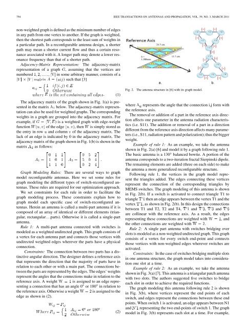
794 <strong>IEEE</strong> TRANSACTIONS ON ANTENNAS AND PROPAGATION, VOL. 59, NO. 3, MARCH 2011non-weighted graph is def<strong>in</strong>ed as the m<strong>in</strong>imum number of edges<strong>in</strong> any path from one vertex to another. If the graph is weighted,then the shortest path corresponds to the least sum of weights <strong>in</strong>a particular path. In a reconfigurable antenna design, a shorterpath may mean a shorter current flow and thus a certa<strong>in</strong> resonanceassociated with it. A longer path may denote a lower resonancefrequency than that of a shorter path.Adjacency-Matrix Representation: The adjacency-matrixrepresentation of a graphnumbered, assum<strong>in</strong>g that the vertices are<strong>in</strong> some arbitrary manner, consists of asuch that [3](1)The adjacency matrix of the graph shown <strong>in</strong> Fig. 1(a) is presented<strong>in</strong> the matrix below. The adjacency-matrix representationcan also be used for weighted graphs. The correspond<strong>in</strong>gweights <strong>in</strong> a graph are grouped <strong>in</strong>to the adjacency matrix. Forexample, ifis a weighted graph with edge-weightfunction of the edge , then is simply stored asthe entry <strong>in</strong> row and column of the adjacency matrix. Thelack of an edge is <strong>in</strong>dicated by 0 <strong>in</strong> the adjacency matrix. Theadjacency matrix of the graph shown <strong>in</strong> Fig. 1(b) is shown <strong>in</strong> thematrix as follows:Graph Model<strong>in</strong>g Rules: There are several ways to graphmodel reconfigurable antennas. Here we set some rules forgraph model<strong>in</strong>g the different types of switch-reconfigured antennas.These rules are required for our optimization approach.We set constra<strong>in</strong>ts for each rule <strong>in</strong> order to facilitate thegraph model<strong>in</strong>g process. These constra<strong>in</strong>ts expla<strong>in</strong> how tograph model each specific case of switch-reconfigured antennas.Here<strong>in</strong> an antenna is called a multi-part antenna if it iscomposed of an array of identical or different elements (triangular,rectangular parts). Otherwise it is called a s<strong>in</strong>gle-partantenna.Rule 1: A multi-part antenna connected with switches ismodeled as a weighted undirected graph. This graph consists ofa vertex for each antenna part and connects those vertices withundirected weighted edges wherever the parts have a physicalconnection.Constra<strong>in</strong>ts: The connection between two parts has a dist<strong>in</strong>ctiveangular direction. The designer def<strong>in</strong>es a reference axisthat represents the direction that the majority of parts have <strong>in</strong>relation to each other or with a ma<strong>in</strong> part. The connections betweenthe parts are represented by the edges. The edges’ weightsrepresent the angles that the connections make <strong>in</strong> relation to thereference axis. A weight is assigned to an edge represent<strong>in</strong>ga connection that has an angle 0 or 180 <strong>in</strong> relation tothe reference axis. Otherwise a weight is assigned to theedge as shown <strong>in</strong> (2).(2)Fig. 2. The antenna structure <strong>in</strong> [6] with its graph model.where represents the angle that the connection i,j form withthe reference axis.The removal or addition of a part <strong>in</strong> the reference axis directionaffects one parameter <strong>in</strong> the antenna radiation characteristics(i.e. S11). The addition or removal of a part <strong>in</strong> a directiondifferent from the reference axis direction affects many parameters(i.e., S11, radiation pattern and polarization); thus the biggerweight.Example of rule 1: As an example, we take the antennashown <strong>in</strong> Fig. 2(a) [6] and model it by a graph follow<strong>in</strong>g rule 1.The basic antenna is a 130 balanced bowtie. A portion of theantenna corresponds to a two-iteration fractal Sierp<strong>in</strong>ski dipole.The rema<strong>in</strong><strong>in</strong>g elements are added (three on each side) to makethe antenna a more generalized reconfigurable structure.Follow<strong>in</strong>g rule 1, the vertices <strong>in</strong> the graph model representthe triangles added. The edges connect<strong>in</strong>g these verticesrepresent the connection of the correspond<strong>in</strong>g triangles byMEMS switches. The graph model<strong>in</strong>g of this antenna is shown<strong>in</strong> Fig. 2(b). If a switch is activated to connect triangle T1 totriangle then an edge appears between the vertex T1 and thevertex , as shown <strong>in</strong> Fig. 2(b). In this design the connectionsbetween T1 and T2, T2 and T4, and , andare coll<strong>in</strong>ear with the reference axis. As a result, the edgesrepresent<strong>in</strong>g these connections are weighted with , andthe other connections are weighted with .Rule 2: A s<strong>in</strong>gle part antenna with switches bridg<strong>in</strong>g overslots is modeled as a non-weighted undirected graph. This graphconsists of a vertex for every switch end-po<strong>in</strong>t and connectsthose vertices with non-weighted edges wherever switches areactivated.Constra<strong>in</strong>ts: In the case of switches bridg<strong>in</strong>g multiple slots<strong>in</strong> one antenna structure, the graph model takes <strong>in</strong>to considerationone slot at a time.Example of rule 2: As an example, we take the antennashown <strong>in</strong> Fig. 3(a) [7]. This antenna is a triangular patch antennawith two slots. The authors suggested five switches to bridgeeach slot <strong>in</strong> order to achieve the required functions.The graph model<strong>in</strong>g this antenna follow<strong>in</strong>g rule 2 is shown<strong>in</strong> Fig. 3(b), where vertices represent the end po<strong>in</strong>ts of eachswitch, and edges represent the connections between these endpo<strong>in</strong>ts. When switch 1 is activated, an edge appears between N1and represent<strong>in</strong>g the two end-po<strong>in</strong>ts of switch 1. The graphmodel <strong>in</strong> Fig. 3(b) represents each slot at a time. For example,