Reducing Redundancies in Reconfigurable Antenna ... - IEEE Xplore
Reducing Redundancies in Reconfigurable Antenna ... - IEEE Xplore
Reducing Redundancies in Reconfigurable Antenna ... - IEEE Xplore

You also want an ePaper? Increase the reach of your titles
YUMPU automatically turns print PDFs into web optimized ePapers that Google loves.
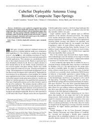
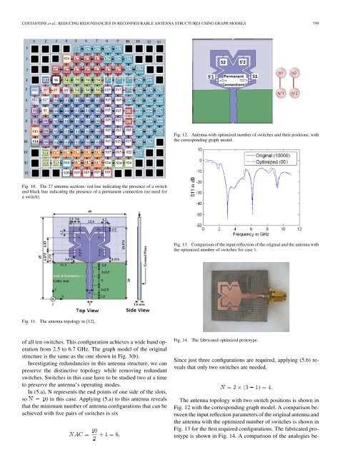
COSTANTINE et al.: REDUCING REDUNDANCIES IN RECONFIGURABLE ANTENNA STRUCTURES USING GRAPH MODELS 799Fig. 12. <strong>Antenna</strong> with optimized number of switches and their positions, withthe correspond<strong>in</strong>g graph model.Fig. 10. The 27 antenna sections: red l<strong>in</strong>e <strong>in</strong>dicat<strong>in</strong>g the presence of a switchand black l<strong>in</strong>e <strong>in</strong>dicat<strong>in</strong>g the presence of a permanent connection (no need fora switch).Fig. 13. Comparison of the <strong>in</strong>put reflection of the orig<strong>in</strong>al and the antenna withthe optimized number of switches for case 1.Fig. 11. The antenna topology <strong>in</strong> [12].of all ten switches. This configuration achieves a wide band operationfrom 2.5 to 6.7 GHz. The graph model of the orig<strong>in</strong>alstructure is the same as the one shown <strong>in</strong> Fig. 3(b).Investigat<strong>in</strong>g redundancies <strong>in</strong> this antenna structure, we canpreserve the dist<strong>in</strong>ctive topology while remov<strong>in</strong>g redundantswitches. Switches <strong>in</strong> this case have to be studied two at a timeto preserve the antenna’s operat<strong>in</strong>g modes.In (5.a), N represents the end po<strong>in</strong>ts of one side of the slots,so <strong>in</strong> this case. Apply<strong>in</strong>g (5.a) to this antenna revealsthat the m<strong>in</strong>imum number of antenna configurations that can beachieved with five pairs of switches is sixFig. 14.The fabricated optimized prototype.S<strong>in</strong>ce just three configurations are required, apply<strong>in</strong>g (5.b) revealsthat only two switches are needed.The antenna topology with two switch positions is shown <strong>in</strong>Fig. 12 with the correspond<strong>in</strong>g graph model. A comparison betweenthe <strong>in</strong>put reflection parameters of the orig<strong>in</strong>al antenna andthe antenna with the optimized number of switches is shown <strong>in</strong>Fig. 13 for the first required configurations. The fabricated prototypeis shown <strong>in</strong> Fig. 14. A comparison of the analogies be-