EasyLab: Model-Based Development of Software for Mechatronic ...
EasyLab: Model-Based Development of Software for Mechatronic ...
EasyLab: Model-Based Development of Software for Mechatronic ...

Create successful ePaper yourself
Turn your PDF publications into a flip-book with our unique Google optimized e-Paper software.
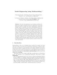
<strong>EasyLab</strong>: <strong>Model</strong>-<strong>Based</strong> <strong>Development</strong> <strong>of</strong> S<strong>of</strong>tware <strong>for</strong> <strong>Mechatronic</strong> SystemsSimon Barner, Michael Geisinger, Christian Buckl and Alois KnollDepartment <strong>of</strong> In<strong>for</strong>maticsTechnische Universität MünchenGarching b. München, Germany{barner,geisinge,buckl,knoll}@in.tum.deAbstract— <strong>Model</strong>-based development tools are one possiblesolution to handle the increasing complexity <strong>of</strong> mechatronicsystems. While traditional approaches <strong>of</strong>ten separate design <strong>of</strong>hardware and s<strong>of</strong>tware, especially in mechatronic systems hardware/s<strong>of</strong>twareinteraction is the most critical component. Hence,both aspects must be considered in this context. The goal is amodel-based development tool <strong>for</strong> s<strong>of</strong>tware/hardware co-designincluding the generation <strong>of</strong> efficient code <strong>for</strong> the respectivetarget plat<strong>for</strong>ms. <strong>EasyLab</strong> is a modular and easily expandabledevelopment tool especially suitable <strong>for</strong> such applications. Itsobjectives are to facilitate reusability and to accelerate thedevelopment process. It raises the level <strong>of</strong> abstraction andthus simplifies the development <strong>of</strong> mechatronic systems even<strong>for</strong> unexperienced users. A graphical user interface providesvarious modeling languages that are easy to use. By employingplat<strong>for</strong>m optimized generation <strong>of</strong> the code, efficiency <strong>of</strong> theresulting programs can be guaranteed, which we demonstrateon a set <strong>of</strong> experimental mechatronic systems.I. INTRODUCTION<strong>Mechatronic</strong> and embedded systems are becoming increasinglycomplex. While sophisticated tools <strong>for</strong> the development<strong>of</strong> the mechanical and electronic parts are available,the implementation <strong>of</strong> the s<strong>of</strong>tware is typically done fromscratch. Due to shortened product life cycles and an emergingneed <strong>for</strong> flexibility, this approach is not feasible anymore. <strong>Development</strong> tools <strong>for</strong> hardware/s<strong>of</strong>tware co-designare required that raise the level <strong>of</strong> abstraction to acceleratethe development process, but guarantee an efficient andreliable implementation to match the resource constraints <strong>of</strong>mechatronic systems.For standard s<strong>of</strong>tware, model-based development [1] hasbecome state <strong>of</strong> the art in s<strong>of</strong>tware engineering. Severalmodel-based development tools, such as Matlab/Simulink[2] or Scade [3] are available <strong>for</strong> the domain <strong>of</strong> embeddedsystems. However, these tools rely on the generation <strong>of</strong>ANSI-C code and there<strong>for</strong>e can only be used to implementthe application functionality. Code <strong>for</strong> hardware related aspectsand other non-functional properties has to be manuallyimplemented by the developer. This code however <strong>for</strong>msthe majority <strong>of</strong> the code required <strong>for</strong> mechatronic systems.The major reason why the generation <strong>of</strong> such code is notsupported is the plat<strong>for</strong>m dependency <strong>of</strong> the code. Due tothe vast heterogeneity <strong>of</strong> hardware [4], it is not possibleto implement a code generator that supports all possiblehardware plat<strong>for</strong>ms a priori. Rather, a suitable developmenttool must be designed in a way that it can be easily expandedto support further plat<strong>for</strong>ms.1-4244-2368-2/08/$20.00 ©2008 IEEEThis paper presents the development tool <strong>EasyLab</strong> thattargets the development <strong>of</strong> mechatronic systems. The maincontributions <strong>of</strong> this work are a tool with a high level <strong>of</strong>abstraction that simplifies and accelerates development, afully modular design to support reusability, a completelyintegrated solution <strong>for</strong> hardware/s<strong>of</strong>tware co-design, and thepossibility to generate efficient, hardware-dependent code.The developer benefits from the abstraction <strong>of</strong> a graphicaldevelopment interface similar to widespread graphical environmentssuch as Matlab/Simulink or LabView. In contrast toexisting tools, <strong>EasyLab</strong> allows the specification <strong>of</strong> hardwarecharacteristics and generation <strong>of</strong> corresponding code. Thetool is expandable in two dimensions: regarding the modelingand the code generation functionality. Expandabilitywith respect to the modeling functionality is achieved byrelying on actor-oriented design [5]. An actor is a s<strong>of</strong>twarecomponent and can <strong>for</strong> instance realize a PID controller, butalso the triggering <strong>of</strong> a sensor or actuator. Expandability withrespect to the code generation functionality is achieved by atemplate-based approach [6]. The main difference betweentemplate-based and component-based [7] approaches is thehigh adaptability <strong>of</strong> templates. It is there<strong>for</strong>e possible togenerate very efficient code [8].The outline <strong>of</strong> this paper is as follows. First, we introducethe Match-X construction kit, which is one <strong>of</strong> the maintarget plat<strong>for</strong>ms <strong>of</strong> <strong>EasyLab</strong>. The main part <strong>of</strong> the papercovers design and implementation <strong>of</strong> <strong>EasyLab</strong>. We introducetwo graphical programming languages as well as other keyfeatures <strong>of</strong> the application, such as code generation andsimulation. To illustrate the s<strong>of</strong>tware modeling process with<strong>EasyLab</strong>, we present two experimental setups that werebuilt during the development <strong>of</strong> <strong>EasyLab</strong>. Finally, we listrelated and future work and summarize the goals and resultspresented in this paper.II. HARDWARE TARGET PLATFORMS<strong>EasyLab</strong> is designed to support different microcontrollerand processor architectures with a rich set <strong>of</strong> peripherals andhas a focus on resource-constrained systems. For an overview<strong>of</strong> <strong>EasyLab</strong>’s capability to model these aspects <strong>of</strong> hardware,see section III-B. To demonstrate the potential <strong>of</strong> our approach,a modular hardware architecture is preferable. Wethere<strong>for</strong>e chose the Match-X construction kit as a referenceplat<strong>for</strong>m which is explained in the following.540
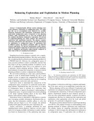
A. The Match-X Construction KitThe Match-X construction kit consists <strong>of</strong> modular componentsthat can be flexibly assembled into complex mechatronicsystems. The construction kit <strong>for</strong>ms the first stage<strong>of</strong> controller hardware development <strong>for</strong> mechatronic systemsand provides a way to efficiently prototype such systems. Thedevelopment process along with mechanical and electricalinterfaces <strong>of</strong> the hardware building blocks are specified in astandard <strong>of</strong> the VDMA 1 [9]. The standard also describes thetransition to small batch production as well as series production.Figure 1 shows the geometry <strong>of</strong> a building block fromthe Match-X construction kit. Figure 2 shows a completelyassembled stack <strong>of</strong> three building blocks. The block at thebottom contains a voltage regulator and features an RS485interface, the block in the middle contains a MicrochipPIC18F2520 microprocessor and the topmost block allowsattachment <strong>of</strong> sensors and actuators. Although the size <strong>of</strong>these building blocks is very small, the microcontroller isclocked with 20 MHz and is thus suitable to per<strong>for</strong>m complexcontroller tasks.Fig. 1.Fig. 2.Pins <strong>of</strong>electricaldata busTop viewSide view0,60mm12,50mm2,54mmGeometry <strong>of</strong> a building block from the Match-X construction kitSensor input /Actuator outputCPUVoltage regulatorConnectorsExample stack <strong>of</strong> three Match-X blocks1 The German Association <strong>of</strong> Machinery Manufacturers.12,50mmB. Other Target Plat<strong>for</strong>msTo point out the universality <strong>of</strong> this approach, <strong>EasyLab</strong>does not only focus on the Match-X hardware constructionkit, but also on a variety <strong>of</strong> other microcontroller plat<strong>for</strong>ms.In this paper, we show the results <strong>of</strong> an evaluation where weused <strong>EasyLab</strong> to design the application logic <strong>for</strong> a complexcontrol task running on an ATMEL ATmega128 microprocessor.We also plan to support other microprocessor typeslike ARM and Fujitsu processors.III. EASYLAB<strong>EasyLab</strong> provides a high-level programming environment<strong>for</strong> the design <strong>of</strong> s<strong>of</strong>tware <strong>for</strong> mechatronic systems. Dueto the raised level <strong>of</strong> abstraction, even people unexperiencedin microcontroller programming can develop complexapplications using various graphical modeling languages.The design process is based on the selection <strong>of</strong> functionalcomponents (actors) that can be connected to <strong>for</strong>m theapplication. One can distinguish between two different types<strong>of</strong> actors: hardware dependent actors (e.g., a s<strong>of</strong>tware componentcontrolling a sensor) and hardware independent actors(e.g., basic mathematical operations or more complex oneslike various controllers). As model <strong>of</strong> computation, the synchronousdata flow model is chosen as it reflects the typicalengineering approach. However, a pure data flow model istoo inflexible to express typical application behavior. Thisissue can be targeted by the combination <strong>of</strong> different models<strong>of</strong> computation (modal models [5]). <strong>EasyLab</strong> combines statemachines with data flow graphs to allow an easy and intuitivemodeling <strong>of</strong> the application. <strong>Based</strong> on the models, the toolallows both simulation and the generation <strong>of</strong> efficient code.The core features <strong>of</strong> <strong>EasyLab</strong> are explained in the following.A. Graphical <strong>Model</strong>ing Languages<strong>EasyLab</strong> supports two graphical modeling languages:1) Structured flow chart: The structured flow chart language(SFC) describes the states <strong>of</strong> a program and how statetransitions are per<strong>for</strong>med. The language has been designedin the style <strong>of</strong> EN 61131-3 [10] (part “SFC”).States <strong>of</strong> SFC programs are references to sub-programsthat can be described in any <strong>of</strong> the available languages. Thus,a state is either an SFC program itself or a reference to anSDF program (see below) which is executed periodically.Consequently, SDF programs are the leaves in the recursivespecification <strong>of</strong> an SFC program. An SFC program hasexactly one initial state.Elements in the SFC language that determine the controlflow are state sequences, alternative branches (conditionalexecution), parallel branches, jumps and program termination.Both sequential and alternative composition are based onconditions that are defined as Boolean expressions consisting<strong>of</strong> Boolean constants and variables as well as comparisons.Comparisons contain arithmetic expressions composed <strong>of</strong>functions and operators on constants and global and localvariables. Local variables refer to values computed rightbe<strong>for</strong>e the respective condition.Figure 3 shows two example programs in SFC language.541
InitAlternative1Anotherstatet 1c 1 c 2Alternative2Parallel1t 1 t 2t 2AnotherstateAlternative2(a)Initt 3Init(b)Parallel2Fig. 3. Example programs in SFC language; (a) alternative branches withBoolean conditions c 1 and c 2 , (b) parallel branches; t 1 , t 2 and t 3 areBoolean transition conditions2) Synchronous data flow: The synchronous data flowlanguage (SDF) consists <strong>of</strong> a directed multigraph where eachnode is the instance <strong>of</strong> a certain actor type. Edges in the graphdenote the data flow between actor instances. An actor typeis defined by a set <strong>of</strong> typed input and output connectorsas well as internal state variables. Furthermore, the actionsstart, stop, step are defined <strong>for</strong> each actor type which areused <strong>for</strong> initialization and finalization as well as to define theactor’s effect. For code generation and simulation, actionsare implemented as code templates and shared librariesrespectively.To support reuse and abstraction, actor types can bedefined using hierarchical composition. Input and outputconnectors <strong>of</strong> a composed actor type A c are mapped todistinguished connectors (named input and output interfaces)<strong>of</strong> an embedded SDF graph defining the step action <strong>of</strong> A c .Output interfaces can be used as local variables in SFCtransition conditions as pointed out above.Variables, namely input/output connectors and state variables,are typed to ensure that only compatible interfacescan be connected. To disambiguate, there may be at mostone edge connected to each input connector.A set <strong>of</strong> predefined primitive data types as well as higheruser-defined data types like arrays and structures are available.A template mechanism allows <strong>for</strong> efficient definition <strong>of</strong>polymorphic operations (e.g., arithmetic operations), while atype coercion algorithm guarantees the generation <strong>of</strong> correctand memory-optimal code [11].The semantics <strong>of</strong> the SDF language is as follows: Whena graph is executed <strong>for</strong> the first time (i.e., the correspondingSFC state has been entered), the actors’ start actions areexecuted (in arbitrary order). While the corresponding SFCprogram remains in the same state, the actors’ step actionsare periodically executed according to a static schedule.When the SFC state is left, the stop actions are executed(in arbitrary order).Various algorithms have been found that statically computevalid schedules <strong>for</strong> multi-rate synchronous data flow graphs(if they exist) and have bounded buffer memory requirements[12], [5]. Depending on the structure <strong>of</strong> the graph, singleappearance schedules can be found to minimize the amount<strong>of</strong> code [13], [14] and buffer sizes [15].The SDF language is designed in the style <strong>of</strong> EN 61131-3[10] (part “FBD”). We will present an example program inSDF language in figure 5 later in this paper.B. Hardware <strong>Model</strong>A key feature in mechatronic systems is the interactionbetween s<strong>of</strong>tware and hardware. However, the interface betweenthese components and <strong>of</strong> course also the hardwareitself varies between different systems. This means thatdesigning applications <strong>for</strong> mechatronic systems can onlysucceed if the modeling tool also allows modeling hardwareaspects <strong>of</strong> the respective systems.<strong>EasyLab</strong>’s hardware model includes all aspects that arenecessary to describe the interaction <strong>of</strong> the s<strong>of</strong>tware part<strong>of</strong> a mechatronic system and the hardware, e.g., sensors,actuators, input and output interfaces. Hence, a device typelibrary specifies which actor instances may be used in acertain hardware environment. In conjunction with a resourcemanagement algorithm, it restricts the user to the set <strong>of</strong>hardware resources that is actually available.The device descriptions also specify how hardware resourcesare represented in the application logic and how theserepresentations are mapped to the real hardware (see alsosection III-D). As <strong>for</strong> actor types in the SDF language, devicetypes are defined using actions start, stop and step specifyingthe behavior when the application starts, terminates or whena single step in the SFC program is per<strong>for</strong>med. To guaranteecorrect operation, access to the underlying hardware isbuffered using a set <strong>of</strong> input and output variables.C. Code Generation<strong>EasyLab</strong> features an integrated code generator that trans<strong>for</strong>msthe application model into code suitable <strong>for</strong> therespective compiler. This is achieved by assigning a codetemplate to each primitive element in the respective modelinglanguage. Currently, models are trans<strong>for</strong>med into C code(supporting the mcc18 and avr-gcc compiler tool chains).In the generated code, each state and transition condition<strong>of</strong> an SFC program is represented as a function per<strong>for</strong>mingan action and returning the address <strong>of</strong> the function to beexecuted next (inspired by the continuation passing style<strong>of</strong> functional programming languages). References to subprogramshave the effect <strong>of</strong> executing the respective programand returning a function to be executed next, usuallythe subsequent transition condition. Functions representingtransition conditions have no side effects and evaluate therespective Boolean expression.While the trans<strong>for</strong>mation <strong>of</strong> SFC programs into executableprograms is straight<strong>for</strong>ward, the implementation <strong>of</strong> multi-ratedata flow graphs into efficient code relies on static schedulingtechniques as pointed out in section III-A.2.542
PistonFig. 4.Analog sensorValves (on the side)Match-X building blocksPneumatic cylinder experimental setuptol gives a certain tolerance <strong>for</strong> the position <strong>of</strong> the pistonto avoid oscillation. The controller regulates the piston to aposition in the interval [pos − tol, pos + tol].valueConstposvalueConsttols1s2sumAdditionsubminvalueAnalog sensordiffSubtractionleftrightltLess thanleftrightgtGreater thanopenValve1retractopenValve2expandsecond one measures the inclination <strong>of</strong> the rod. The onlyactuator is the electric motor, <strong>for</strong> which we regulate thevoltage.To demonstrate the efficiency <strong>of</strong> the code generated by<strong>EasyLab</strong>, we implemented the system using an ATMEL ATmega128microcontroller with a clock frequency <strong>of</strong> 16 MHz.First, we augmented <strong>EasyLab</strong> to allow us to access the sensorvalues necessary to achieve the task. For this purpose, weadded a new actor type that returns the current value <strong>of</strong> therespective sensor as well as its derivative.A suitable controller <strong>for</strong> a self-erecting inverted pendulumconsists <strong>of</strong> two modes (swing-up and balance), which areimplemented in terms <strong>of</strong> the SFC program depicted infigure 7. The controller used to erect the rod is based on aheuristic using a proportional-velocity cart position controllerthat swings the rod back and <strong>for</strong>th until the rod has amaximum deviation <strong>of</strong> ε to the upright position (first statein SFC program and subsequent transition condition). Thesecond state corresponds to the execution <strong>of</strong> the balance SDFprogram according to equation (1) (see below), which canbe derived from a linear state-space model <strong>of</strong> the pendulumusing the linear quadratic regulator (LQR) technique. Whilethe balance state is never left, the final jump was added toobtain a well-<strong>for</strong>med program.Swing-upFig. 5.Pneumatic cylinder controller in SDF language|α i | < εB. Inverted PendulumThe second experiment, a more complex control taskpoints out the efficiency <strong>of</strong> the generated code. The invertedpendulum is a well-known experimental setup to demonstratecontrol tasks [19]. It consists <strong>of</strong> an electric motor thatdrives a cart mounted on a linear rail. A rod that can befreely deflected is attached to the cart. Figure 6 shows theexperimental setup.Rotation sensor attachedto pendulum axisFreely deflectable rodElectric motor,rotation sensorattached to motor axisFig. 7.Balance⊥Swing-upInverted pendulum SFC programFor the ith step, let α i be the inclination <strong>of</strong> the rod (inradiants), ∂α i the angular velocity and let α i = 0 if the rodis in erect position. Let c i be the position <strong>of</strong> the cart, ∂c i itsvelocity and c = 0 if the cart is in its center position. Thena PID controller used to balance the pendulum in uprightposition can be defined as follows, where U n is the voltageto drive the motor with at step n ≥ 0 (constants k 1 , . . . , k 6depend <strong>of</strong> the physical characteristics <strong>of</strong> the rod):Fig. 6.Inverted pendulum experimental setupThe goal <strong>of</strong> the experiment is to accelerate the pendulumby moving the cart from one side to the other until the rodis in an upright position and hold the rod in that positionafterwards. During both stages, the cart should be aligned tothe center <strong>of</strong> the rail to prevent it from moving <strong>of</strong>f the rail.The experimental setup features two sensors and oneactuator: one sensor measures the position <strong>of</strong> the cart, theU n = k 1 · α n + k 2 · ∂α n + k 3 ·+ k 4 · c n + k 5 · ∂c n + k 6 ·n∑i=0α in∑c i (1)i=0The trans<strong>for</strong>mation <strong>of</strong> above <strong>for</strong>mula into an SDF programis straight<strong>for</strong>ward.544
V. RELATED WORK<strong>EasyLab</strong> is unique in the sense that it supports hardware/s<strong>of</strong>twareco-design without focusing on a specific set<strong>of</strong> hardware plat<strong>for</strong>ms. It is expandable both regarding modelingand code generation.Several other tools and projects influenced the development<strong>of</strong> <strong>EasyLab</strong>. The graphical user interface is in thestyle <strong>of</strong> state-<strong>of</strong>-the-art tools like Matlab/Simulink [2] thatalso provide data flow design based on actors. The theorybehind actors is however derived from the project Ptolemy[5]. In contrast to both tools, <strong>EasyLab</strong> augments the notion<strong>of</strong> actors by introducing hardware related actors which isa precondition <strong>for</strong> successful hardware/s<strong>of</strong>tware co-design.The introduction <strong>of</strong> typed data flow allows <strong>for</strong> the generation<strong>of</strong> code tailored to resource-constrained target architectures.<strong>EasyLab</strong> uses synchronous data flow graphs and structuredflow charts as model <strong>of</strong> computation, as defined in EN61131-3 [10]. While there are several other tools such asCoDeSys that are compliant with this norm, <strong>EasyLab</strong> is theonly one that can be augmented <strong>for</strong> a specific hardware plat<strong>for</strong>mand can thus generate optimized hardware-dependentcode. The concept <strong>for</strong> code generation is based on previouswork on template-based code generation [6], [20].VI. SUMMARYIn this work, we presented a new model-based programmingtool <strong>for</strong> mechatronic systems. In contrast to well-knowntools from the world <strong>of</strong> embedded systems, <strong>EasyLab</strong> alsoprovides components that are specialized <strong>for</strong> mechatronicsystems, where the diversity <strong>of</strong> the used hardware is muchmore relevant than in other types <strong>of</strong> embedded systems.We have also shown that <strong>EasyLab</strong> allows both modeling <strong>of</strong>s<strong>of</strong>tware and hardware functionality and introduced the twographical modeling languages that have been implementedso far, namely synchronous data flow (SDF) and state flowcharts (SFC).Finally, we presented two demonstration setups thatshowed that the workflow <strong>of</strong> programming mechatronicsystems is the same <strong>for</strong> different types <strong>of</strong> microprocessorplat<strong>for</strong>ms. The inverted pendulum setup demonstrates thatthe code generated by <strong>EasyLab</strong> per<strong>for</strong>ms well and is suitable<strong>for</strong> real-time control tasks.VII. FUTURE WORKWe are currently working on a remote debugging facility<strong>for</strong> programs generated by <strong>EasyLab</strong> whose purpose is toprovide transparent real-time access to the state <strong>of</strong> a mechatronicsystem at the granularity <strong>of</strong> the underlying model.It is based on code instrumentation and a marshaling layerthat is tailored to the resources and communication interfacesthat are available in typical embedded systems. Thus, firmlyintegrated inspection and manipulation <strong>of</strong> both data andprogram state at the model level will increase the abstractionalso in the debugging phase <strong>of</strong> the product developmentcycle.We also plan to extend <strong>EasyLab</strong> to support networked(distributed) mechatronic systems. The time-triggered model[21] seems to be a feasible approach that integrates well withthe synchronous data flow employed in the current stage.VIII. ACKNOWLEDGMENTThis work is funded by the German Ministry <strong>of</strong> Educationand Research.REFERENCES[1] Joaquin Miller and Jishnu Mukerji, MDA Guide, Object ManagementGroup, Inc., June 2003, Version 1.0.1 (omg/03-06-01).[2] Paul Barnard, “S<strong>of</strong>tware <strong>Development</strong> Principles Applied to Graphical<strong>Model</strong> <strong>Development</strong>,” in AIAA <strong>Model</strong>ing and Simulation TechnologiesConference and Exhibit, San Francisco, Aug. 2005.[3] B. Dion, T. Le Sergent, B. Martin, and H. Griebel, “<strong>Model</strong>-baseddevelopment <strong>for</strong> time-triggered architectures,” in Digital AvionicsSystems Conference, 2004. DASC 04. The 23rd, 2004, vol. 2, pp.6.D.3– 6.1–7.[4] Shankar Sastry, Janos Sztipanovits, R. Bajcsy, and H. Gill, “Scanningthe issue - special issue on modeling and design <strong>of</strong> embeddeds<strong>of</strong>tware.,” Proceedings <strong>of</strong> the IEEE, vol. 91, no. 1, pp. 3–10, 2003.[5] Edward A. Lee, “Overview <strong>of</strong> the Ptolemy project,” Tech. Rep.UCB/ERL M03/25, EECS Department, University <strong>of</strong> Cali<strong>for</strong>nia,Berkeley, July 2003.[6] A. Singh, J. Schaeffer, and M. Green, “A template-based approachto the generation <strong>of</strong> distributed applications using a network <strong>of</strong>workstations,” IEEE Transactions on Parallel and Distriuted Systems,vol. 2, no. 1, pp. 52–67, Jan. 1991.[7] Clemens Szyperski, Component S<strong>of</strong>tware, Addison-Wesley Pr<strong>of</strong>essional,Nov. 2002.[8] Christian Buckl, Alois Knoll, and Gerhard Schrott, “<strong>Model</strong>-baseddevelopment <strong>of</strong> fault-tolerant embedded s<strong>of</strong>tware,” in Second InternationalSymposium on Leveraging Applications <strong>of</strong> Fomal Methods,Verification and Validation (IEEE-ISoLA). 2007, pp. 103–110, IEEE.[9] Arbeitsgemeinschaft Match-X, VDMA Einheitsblatt VDMA 66305:Bausteine und Schnittstellen der Mikrotechnik, Verband DeutscherMaschinen- und Anlagenbau e.V., July 2005, http://www.match-x.org/.[10] International Electrotechnical Commission, Norm EN 61131, 2003.[11] John C. Mitchell, “Coercion and type inference,” in POPL ’84: Proceedings<strong>of</strong> the 11th ACM SIGACT-SIGPLAN symposium on Principles<strong>of</strong> programming languages, New York, NY, USA, 1984, pp. 175–185,ACM.[12] Edward Ash<strong>for</strong>d Lee and David G. Messerschmitt, “Static scheduling<strong>of</strong> synchronous data flow programs <strong>for</strong> digital signal processing,” IEEETrans. Comput., vol. 36, no. 1, pp. 24–35, 1987.[13] Shuvra S. Battacharyya, Edward A. Lee, and Praveen K. Murthy, S<strong>of</strong>twareSynthesis from Dataflow Graphs, pp. 50–51, Kluwer AcademicPublishers, Norwell, MA, USA, 1996.[14] Shuvra S. Bhattacharyya, Joseph T. Buck, Soonhoi Ha, and Edward A.Lee, “Generating compact code from dataflow specifications <strong>of</strong>multirate signal processing algorithms,” pp. 452–464, 2002.[15] Hyunok Oh, N. Dutt, and Soonhoi Ha, “Memory optimal singleappearance schedule with dynamic loop count <strong>for</strong> synchronousdataflow graphs,” in Design Automation, 2006. Asia and South PacificConference on, 24-27 Jan. 2006, p. 6pp.[16] Adam Dunkels, Programming Memory-Constrained Networked EmbeddedSystems, Ph.D. thesis, Swedish Institute <strong>of</strong> Computer Science,February 2007.[17] P. Levis, S. Madden, J. Polastre, R. Szewczyk, K. Whitehouse, A. Woo,D. Gay, J. Hill, M. Welsh, E. Brewer, and D. Culler, “TinyOS: AnOperating System <strong>for</strong> Sensor Networks,” pp. 115–148. 2005.[18] Richard Barry, “FreeRTOS,” 2008, http://www.freertos.org/.[19] K. J. Astrom and K. Furuta, “Swinging up a pendulum by energycontrol,” IFAC 13th World Congress, 1996.[20] Markus Voelter, Christian Salzmann, and Michael Kircher, “<strong>Model</strong>driven s<strong>of</strong>tware development in the context <strong>of</strong> embedded componentinfrastructures,” in Component-<strong>Based</strong> S<strong>of</strong>tware <strong>Development</strong> <strong>for</strong> EmbeddedSystems, number 3778 in Lecture Notes in Computer Science,pp. 143–163. Springer, 2005.[21] Hermann Kopetz and Günther Bauer, “The time-triggered architecture,”Proceedings <strong>of</strong> the IEEE, Special Issue on <strong>Model</strong>ing and Design<strong>of</strong> Embedded S<strong>of</strong>tware, 2001.545