Model Engineering using Multimodeling * - Robotics and Embedded ...
Model Engineering using Multimodeling * - Robotics and Embedded ...
Model Engineering using Multimodeling * - Robotics and Embedded ...

Create successful ePaper yourself
Turn your PDF publications into a flip-book with our unique Google optimized e-Paper software.
<strong>Model</strong> <strong>Engineering</strong> <strong>using</strong> <strong>Multimodeling</strong> ⋆Christopher Brooks 1 , Chih-Hong Cheng 2 , Thomas Huining Feng 1 ,Edward A. Lee 1 , <strong>and</strong> Reinhard von Hanxleden 31 University of California at Berkeley (cxh,tfeng,eal@eecs.berkeley.edu)2 National Taiwan University (patrickjeng@gmail.com)3 University of Kiel (rvh@informatik.uni-kiel.de)Abstract. We study the simultaneous use of multiple modeling techniquesin the design of embedded systems. We begin with a pre-existingStatecharts model of a simple case study, a traffic light for a pedestriancrossing, <strong>using</strong> it to illustrate the need for multimodeling <strong>and</strong> the pitfalls.The original model combines two distinct models of computation(MoCs), finite state machines (FSMs) <strong>and</strong> synchronous/reactive (SR).We add an additional MoC, a discrete-event (DE) model of the environmentin which the traffic light operates, including a simple fault model,yielding a model that combines three different modeling techniques. Weconstruct a second model of a hardware deployment <strong>and</strong> a third modelthat is an abstraction used for formal verification. The result is thatthis simple example uses three distinct models of the system (functional,deployment, verification), two of which hierarchically combine distinctmodeling techniques (DE, SR, FSM). This exercise reveals some pitfallsof model-based design where multiple models are needed as well as someof the opportunities.1 Introduction<strong>Multimodeling</strong> is the act of combining diverse models. We consider two formsthat this can take. In the first form, hierarchical compositions of distinct modelingstyles are combined to take advantage of the unique capabilities <strong>and</strong> expressivenessof the distinct modeling styles. In the second form, distinct <strong>and</strong> separatemodels of the same system are constructed to model different aspects of the system.We call the first form hierarchical multimodeling <strong>and</strong> the second formmulti-view modeling.This paper starts with a simple traffic light controller given as a Statechartsmodel, <strong>and</strong> interprets it as a hierarchical multimodel. This model is simple⋆ This work was supported in part by the Center for Hybrid <strong>and</strong> <strong>Embedded</strong> SoftwareSystems (CHESS) at UC Berkeley, which receives support from the National ScienceFoundation (NSF awards #0720882 (CSR-EHS: PRET) <strong>and</strong> #0720841 (CSR-CPS)),the U. S. Army Research Office (ARO #W911NF-07-2-0019), the U. S. Air ForceOffice of Scientific Research (MURI #FA9550-06-0312), the Air Force Research Lab(AFRL), the State of California Micro Program, <strong>and</strong> the following companies: Agilent,Bosch, HSBC, Lockheed-Martin, National Instruments, <strong>and</strong> Toyota.
enough to be fully described in a short paper, <strong>and</strong> yet rich enough to illustratemany major design issues. We first show an equivalent model constructed withPtolemy II [13] that is much more explicit about the fact that this is a hierarchicalmultimodel that combines two distinct modeling formalisms (state machines<strong>and</strong> synchronous/reactive models). We next show that the model can be considerablyenriched with a third modeling formalism, discrete events, somethingthat is not possible <strong>using</strong> Statecharts alone. The resulting model is a hierarchicalmultimodel of the functionality of a simple traffic light interacting with theenvironment in which it operates.We continue by constructing a deployment model, which models a hardwareimplementation (in our example, two components of the traffic light communicatewirelessly). The deployment model <strong>and</strong> the functional model togetherare a form of multi-view modeling. The distinct models share certain components.We show that we can use actor-oriented classes [26] to maintain consistencyacross these distinct models. That is, as the models evolve, their sharedcomponents remain identical.We show that the process of constructing the deployment model reveals thatthe original functional model is not agnostic about implementation. Particularchoices made in the functional model are inconsistent with the wireless deploymentthat we selected. Maintaining orthogonality between models in multi-viewmodeling is challenging. As additional models are constructed for distinct views,refactoring of previously constructed models invariably becomes necessary.A third kind of model is often required for safety-critical embedded systems.In particular, the functional <strong>and</strong> deployment models may be too detailed foreffective use of formal verification techniques such as model checking, <strong>and</strong> mayinclude complicated temporal dynamics that are difficult to h<strong>and</strong>le. We illustratean applied verification technique where we synthesize from the functional model<strong>using</strong> code generation technology an SMV (Symbolic <strong>Model</strong> Verifier) model thatcan be used to check safety properties via model checking. This reveals thatwhile the functional model satisfies a key safety requirement, the refactoreddeployment model does not.2 Related WorkOne of the key innovations in Statecharts [19] is the introduction of concurrency(“<strong>and</strong> states”), as well as hierarchy, to state machine models. There exist severalvariants of Statecharts, which differ in the precise timing <strong>and</strong> concurrencymodels <strong>and</strong> other aspects such as possible reaction to signal absence; von derBeeck [5] compares 21 dialects, <strong>and</strong> since then numerous other variants have beendeveloped, such as Simulink/Stateflow <strong>and</strong> UML Statecharts. We here presumea “fully synchronous” semantics of Statecharts, as embodied in SyncCharts [2],also called Safe State Machines (SSMs) [3], <strong>and</strong> use the SyncChart graphical syntax.However, for the case study discussed here, other semantics such as Harel’soriginal semantics or the Stateflow semantics produce equivalent results.
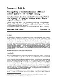
Statecharts can be viewed as a hierarchical mix of a state machine model <strong>and</strong>a synchronous/reactive (SR) concurrent model of computation (MoC) [6]. Thisis a form of hierarchical multimodeling. This idea has been generalized, showingthat other concurrent MoCs can be usefully combined with state machines [15].That work followed on Ptolemy Classic [9], which provided a software architecturesupporting a general form of hierarchical multimodeling. In [9], Buck et al.showed how to apply hierarchical multimodeling in applications that combinednetworking <strong>and</strong> signal processing. Hierarchical multimodeling has also been elaboratedin ForSyDe [22], SPEX [28], <strong>and</strong> ModHelX [18]. A non-hierarchical approachto multimodeling is provided by Metropolis [16] <strong>and</strong> Colif [10]. Thisapproach does not segregate distinct models of computation hierarchically.Ptolemy Classic [9] also illustrates multi-view modeling applied to hardware/softwarecodesign. One model specifies functionality <strong>and</strong> one specifies hardwarearchitecture. This concept has been elaborated into a sophisticated methodologyfor hardware/software codesign called Y Charts [24], <strong>and</strong> has been developedinto design tools like Metropolis [16]. Multi-view modeling has also formeda centerpiece of model-integrated computing [32] <strong>and</strong> has been applied in anumber of large-scale system designs [17]. Multi-view modeling in the sense ofproviding alternative views of the same system, e. g. dynamically created duringa simulation, is investigated by the KIEL system [31].A third form of multimodeling, where a single model can be specialized tomultiple distinct implementations [29], is not discussed in this paper. In thispaper, we use a simple traffic light controller to illustrate the issues in multiviewmodeling. A similar approach is taken by Feng, Zia, <strong>and</strong> Vangheluwe [14].Our approach was also influenced by Huang [21]. We also leverage actor-orientedclasses [26, 23, 25] to maintain consistency across multi-view models.3 The Traffic Control <strong>Model</strong>A Statecharts model [19] of a simple traffic light controller is shown in Fig. 1.The module TRAFFIC LIGHT has two states. The left state (the initial state)represents normal operation, <strong>and</strong> the right state represents error condition operation.The transition to the error state is triggered by an unspecified externalevent called Error, <strong>and</strong> the transition back to the normal state by another externalevent called Ok. Each of the normal <strong>and</strong> error states contains two concurrentstate machines, one governing the operation of a pedestrian light <strong>and</strong> the othergoverning the operation of a car light. To determine the initial state of the pedestrianlight, follow from the “I” bubble through the “C” (connector) bubble alongthe arc labeled /Pred(1), Pgrn(0). The (unlabeled) state at the end of that arcis the initial state.In Statecharts, arcs are labeled with guard/action, where the guard specifiesthe conditions under which the transition is taken. The label /Pred(1), Pgrn(0)does not include a guard, so the transition is taken unconditionally. The actionPred(1), Pgrn(0) assigns to variable Pred (for “pedestrian red light”) the value 1,
Fig. 1. A Statecharts model of a simple traffic light controller.which we interpret to mean to illuminate the pedestrian red light. The pedestriangreen light is turned off by the action Pgrn(0).The transition labeled Pgo / Pred(0), Pgrn(1) is triggered by the event Pgo(for “pedestrian go”) <strong>and</strong> turns off the red light <strong>and</strong> on the green. The transitionlabeled Pstop specifies only a guard, no action. This transition is triggered by thesignal Pstop, <strong>and</strong> then proceeds instantaneously through the connector bubble<strong>and</strong> along the transition labeled /Pred(1), Pgrn(0), which specifies an action.The concurrent car control state machine is to the right of the dashed linethat separates it from the pedestrian light control state machine. It has fourstates, <strong>and</strong> <strong>using</strong> a similar notation, turns on <strong>and</strong> off red, yellow, <strong>and</strong> greenlights for the cars. For example, the action Cred(1) turns on the car red light.The car state machine has an additional notation where a guard like 2 Sec isgiven. This specifies that the transition is triggered after remaining in the previousstate for two consecutive instances of the event Sec. This event is suppliedby the environment, in this case to indicate the passage of one second. Note thatat this level we do not explicitly model physical time as part of our semantics,but instead assume it is supplied by the environment. This differs from Harel’soriginal Statechart dialect, which did include a timeout mechanism as part of thelanguage. Instead, we adopt the multiform notion of time, where the passage oftime is seen just as any other event, such as passage of distance, <strong>and</strong> is h<strong>and</strong>ledwith the same mechanisms [8]. The error state on the right can now be easilyread, knowing the notation. It turns off both the red <strong>and</strong> the green pedestrianlights, <strong>and</strong> blinks the car yellow light.
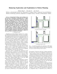
4 Hierarchical <strong>Multimodeling</strong>Statecharts can be viewed as a hierarchical combination of synchronous/reactive(SR) models <strong>and</strong> finite state machines (FSMs). The “<strong>and</strong> states” compose componentsaccording to the SR concurrency model, while the “or states” describeclassical FSMs [19].TrafficLightError.CarLightNormalErrorNormal.PedestrianLightError.PedestrianLightNormal.CarLightFig. 2. The traffic light controller in Ptolemy II.In this paper, we use Ptolemy II [13] as a laboratory for experimenting withmodel engineering precisely because it embraces all the forms of multimodelingin which we are interested. In Ptolemy II, the hierarchical combination of MoCsis more explicit than in Statecharts. A Ptolemy II model equivalent to that ofFig. 1 is shown in Fig. 2. The top level of the hierarchy, labeled TrafficLight, justlike Fig. 1, shows two states, Normal <strong>and</strong> Error. Unlike the Statecharts model, thisfigure also shows explicitly the three external inputs that need to be provided(Sec, Error, <strong>and</strong> Ok). In the graphical part of the Statecharts model, one canonly infer from the fact that these events are mentioned <strong>and</strong> not asserted anywherethat they are in fact external inputs. The Ptolemy II model also explicitly
shows five outputs (Pred, Pgrn, Cred, Cyel, <strong>and</strong> Cgrn), which control whether thepedestrian <strong>and</strong> car lights are on or off.The transitions between the normal <strong>and</strong> error states are labeled with guards,Ok isPresent <strong>and</strong> Error isPresent. This means that these transitions are triggeredby the presence of these externally provided events.The normal <strong>and</strong> error states have refinements, shown in boxes labeled Normal<strong>and</strong> Error. These refinements inherit the input <strong>and</strong> output ports from the TrafficLightmodel. The refinements, however, have a different model of computation.Their MoC is indicated by the director, labeled SR Director, which specifies asynchronous/reactive MoC.In Ptolemy II, states in state machines can have refinements, as in TrafficLight,<strong>and</strong> hence are called modal models [15] to distinguish them fromclassical state machines. This mirrors the hierarchy in Statecharts. The statesrepresent modes of operation, <strong>and</strong> in each mode, the behavior is given by the refinement.In Ptolemy II, the semantics are that when a modal model fires (whichin the SR MoC occurs on each tick of a global clock [6]), the refinement of thecurrent state is fired, then the guards on all outgoing transitions are evaluated.If exactly one of those guards is true, then the transition is taken <strong>and</strong> the actionson the transition are executed. If more than one of the guards is true, thenunless the transitions are marked to tolerate nondeterminacy, an exception willbe thrown. If the transitions are so marked, then one of the enabled transitionsis chosen arbitrarily.The Normal refinement itself contains two components. Since these will executeunder the SR MoC, they are concurrent, corresponding to the “<strong>and</strong> states”of Fig. 1. Unlike Fig. 1, the communication between these concurrent componentsis explicit in the Ptolemy II model. In the Statecharts model, two concurrentstate machines communicate if one issues an event that is used by the other(e. g. to trigger a transition). The fact that communication is occurring mustbe inferred by the reader by matching the names of the events. In Ptolemy II,the names need not match; the communication is indicated instead by “wires”connecting the concurrent components. (In Fig. 2 the names on the wires connectingCarLight to PedestrianLight in Normal match only to correspond with theStatecharts model.)There is an advantage to explicitly showing the connections between concurrentcomponents, rather than relying on name matching. In particular, fromlooking at Fig. 1, it is very hard to tell whether there is feedback between the“<strong>and</strong> states.” That is, it is hard to tell whether one state issues an event e 1 inresponse to event e 2 , where e 2 is issued in response to e 1 . The fact that thereis no such feedback is visible in the syntax in Fig. 2, but not in Fig. 1. Notethat both SCADE <strong>and</strong> Esterel-Studio also support such an explicit syntax [7].In Fig. 2, we see that Normal.CarLight provides the Pgo <strong>and</strong> Pstop events toNormal.PedestrianLight, <strong>and</strong> that otherwise, there is no communication betweenthese concurrent components.Normal.CarLight <strong>and</strong> Normal.PedestrianLight are themselves modal models,but where the states have empty refinements. These, therefore, are classical
(extended) finite state machines. The extension is that in addition to a finiteset of ordinary states (indicated by ellipses), the state machine can have localvariables that have a value. In particular, Normal.CarLight has a variable count,shown at the lower left, which is used to measure the passage of time. Thus, unlikeFig. 1, there is no special syntax for triggers that consider multiple consecutiveoccurrences of an event. Instead, the variable count is updated in the actions onthe transitions <strong>and</strong> evaluated in the guards.Examining Normal.CarLight, we see that transitions all have a guard, whichis an expression that when true triggers the transition. If the guard is true, as itis on the transition between Cinit <strong>and</strong> Cred, then the transition will be taken onthe first tick of the SR clock. Transitions with guard Sec isPresent are triggeredwhen the Sec input is present. This input is provided by the environment. Ourdesign assumes that it is provided once per second.The actions associated with each transition are divided into two categories,output actions <strong>and</strong> set actions. In the model of Fig. 2, there is no materialdifference between these because the SR model has no feedback. When an SRmodel has feedback, however, then at each tick of the SR clock there is aniteration to a fixed point. Such an iteration requires that components be able toassert output values without committing to state transitions. Since our examplehas no feedback, we do not discuss this further. You can assume that when atransition is triggered, both the output <strong>and</strong> set actions are executed.In Normal.CarLight, you can see that output actions are used to turn lightson <strong>and</strong> off, while set actions are used to control the value of the count variable.You can also see that all guards are carefully defined to ensure that there isno nondeterminacy in the model. It is a convenient feature of Ptolemy II thatmodal models are checked (at run time) for nondeterminate behavior. 4At the top level (TrafficLight), when a transition is taken from Normal to Erroror vice versa, the refinement of the destination mode is re-initialized. Thus, thestate machines in Normal.CarLight, Normal.PedestrianLight, Error.CarLight, <strong>and</strong>Error.PedestrianLight will always start in their initial state. In the Ptolemy IIsyntax, this fact is indicated by the hollow arrowheads on the transitions inTrafficLight.The only additional syntax needed to read Fig. 2 is the final state in Error.PedestrianLight,which is shown with a double ellipse. This is similar to thedouble circle in Fig. 1. In Ptolemy II, when this final state (labeled Done) isentered, the enclosing modal model (labeled PedestrianLight in the Error model)will henceforth be omitted from executions by the enclosing SR Director. Thatis, on subsequent ticks of the SR clock, the PedestrianLight actor will not be fired<strong>and</strong> its outputs will be deemed to be absent.We can gain some insight by comparing the syntaxes of figures 1 <strong>and</strong> 2.In particular, we see that Fig. 2 is larger (more verbose). However, it is also4 Since guards <strong>and</strong> transitions involve arbitrary operations on variables, the questionof whether a modal model is determinate is undecidable in general. However, it isfeasible to perform static checks at least for a decidable subset, e.g. by interfacingthe modeling tool to a theorem prover [20].
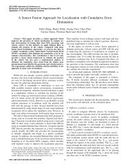
more explicit about key information, such as whether there is communicationbetween concurrent components. Moreover, it is much more literally hierarchical,<strong>and</strong> thus, at each level of the hierarchy, the diagram presents a simple abstractedview of the system. Such an explicitly hierarchical syntax may scale more easilyto large models. Moreover, we will show below that it facilitates sharing of modelcomponents across distinct models. Note that although the model in Fig. 1 usesa single sheet, Statechart tools typically allow to spread different hierarchy levelsacross several sheets as well, i. e., both of the parallel macro states could havebeen placed into separate sheets.We consider these as different, equivalent views of a model. Ideally, the modelercould freely choose among these. It is quite conceivable to have the modelingtool synthesize such views automatically, by transforming them into each otheror by synthesizing them from a separate source. In fact, the Statechart in Fig. 1has been synthesized from an equivalent, textual Esterel description [30], <strong>and</strong> itseems feasible to alternatively synthesize the model in Fig. 2.5 <strong>Model</strong>ing the EnvironmentThe top levels in figures 1 <strong>and</strong> 2 present incomplete models. In particular, theyboth rely on external inputs to have any behavior at all. In the Statecharts model,if we were to provide a model of the environment that provides these signals,it would have to conform with the Statecharts semantics. Thus, we would berestricted to SR for concurrency <strong>and</strong> FSMs for state machines. Neither of theseis rich enough to correctly model the environment for this problem.In Ptolemy II, we are not constrained to SR for the concurrency model. Infact, many concurrent MoCs have been implemented in Ptolemy II, <strong>and</strong> manycan be combined hierarchically with SR. For our purposes here, the most naturalMoC for modeling the environment is discrete events (DE), implemented by theDE Director in Ptolemy II.In the DE MoC, actors communicate by sending each other time-stampedevents. The DE Director fires actors in time-stamp order. The semantics ofDE is shown in [27] to be a generalization of the SR semantics. Because itis a generalization, the hierarchical combination of the two MoCs is clean <strong>and</strong>rigorously defined. Very simply, if a DE actor is fired in response to time stampedevents, <strong>and</strong> that DE actor internally contains an SR model, then the SR modelexecutes one “tick” of its clock.A simple model of the environment for our traffic light example is shown inFig. 3. The TrafficLight actor is the modal model shown in Fig. 2. It has threeinputs, Sec, Error, <strong>and</strong> Ok. It will fire when any of these three inputs containsthe oldest (least time stamp) event in the system. The Sec input is driven by aClock actor, which produces an event once per second. The Error input is drivenby a PoissonClock actor, which produces events according to a Poisson process.A parameter of that actor specifies the mean interarrival time of those events.
Fig. 3. A DE model of the traffic light environment in Ptolemy II.In our simple environment model, the Ok input receives an event five secondsafter the error event occurs. This models a fixed (<strong>and</strong> unrealistic) repair time.But it is easy to see how more interesting models could be constructed.The outputs of the TrafficLight actor are wired to instances of the SetVariableactor. These instances record the values in variables shown at the top of thediagram, Pred, Pgrn, Cred, Cyel, <strong>and</strong> Cgrn. The reason for doing this is that wecan exploit a feature of Ptolemy II <strong>and</strong> create an interactive animation of theexecution of this model. In particular, the circles on the right of the diagramhave colors that set by expressions that depend on these variables. For example,the top-most circle has its fill color defined by the expression(Pred == 1) ? {1.0, 0.0, 0.0, 1.0}: {1.0, 1.0, 1.0, 1.0}This means that if the variable Pred has value 1, the color is red, <strong>and</strong> otherwisethe color is white. 5 Thus, when executing the model, the circles change colorsjust as the lights in a traffic light would.6 The Deployment <strong>Model</strong>The model of Fig. 2 describes the functionality of the traffic light without particularconcern for how it is implemented. Suppose that to implement this, twomicrocontrollers are used, one for the car light <strong>and</strong> one for the pedestrian light.Suppose further that these two microcontrollers communicate with one anothervia a wireless radio link. A model that describes this architecture is called adeployment model.Such a model is shown in figures 4 <strong>and</strong> 5. The top level of this model usesthe WirelessDirector, a generalization of the DE Director that supports wirelesscommunication models [4]. Semantically, the Wireless MoC is identical to DE.Syntactically, communication between actors is indicated not by wires but byidentifying a wireless channel model (labeled RadioChannel in the figure) that5 Colors are defined by an array R, G, B, A, specifying red, green, blue, <strong>and</strong> alphavalues. When these values are 1.0, the corresponding color is fully present. Whenthe alpha value is 1.0, the color is opaque.
Fig. 4. Wireless deployment, showing the car light model.Fig. 5. Wireless deployment, showing the pedestrian light model.mediates the communication. In principle, the RadioChannel actor can modelarbitrary properties of the radio link, including reliability, interference, <strong>and</strong> securityproperties. In the model we built, it models only the limited range of theradio communication.At the top level, the CarLight <strong>and</strong> PedestrianLight actors have icons constructedby the model engineer that contain circles that change color in response
to changes in the values of their parameters. The output port of the CarLightactor communicates wirelessly via the RadioChannel actor to the single inputport of the PedestrianLight actor.Inside the CarLight actor we see a model of the hardware of the car light.It includes a Clock actor that provides one clock tick per second, <strong>and</strong> a PoissonClockactor that models hardware faults. We observe that in this model,hardware faults need to be modeled at the local level, inside the CarLight model,whereas in Fig. 2 they are modeled at the systemwide level. Although this seemedreasonable when we constructed the functional model, because of the choice ofdeployment, where the car light <strong>and</strong> the pedestrian light are on distinct hardwareplatforms, that original choice proves awkward. There is no global normal<strong>and</strong> error state; each component has to separately decide whether it is in thenormal or error state. Maintaining coherence of these decisions turns out to bean important aspect of the design, absent from the functional model. In fact,in our model, if the car light fails, it sends a failure message to the pedestrianlight, which then turns off. However, if the pedestrian light fails, the car lightcontinues operating normally. This is not a desirable property of the system.A designer faces two choices: she could refactor the functional model in Fig. 2to put the normal <strong>and</strong> error states lower in the hierarchy, or she could interpretthe original design as an abstraction <strong>and</strong> create a new model for the deployment.Here we do the latter. Consequently the two models share less of the design thanthey could. Our decision, however, was to share as much as possible withoutmodifying the original design. This reflects the practicalities of system design ona large team, where changing designs is not always possible.The original Statecharts model that we worked with was a European design,<strong>and</strong> consequently turned on red <strong>and</strong> yellow lights simultaneously before switchingto green. What if we wanted to change the design to the American system, wherewe move directly from red to green? Is there any way this change could be madein one place <strong>and</strong> apply to both the functional model <strong>and</strong> the deployment model?Our model uses instances of two actor-oriented classes [26] to accomplishthis objective. The CarLight <strong>and</strong> PedestrianLight actors in figures 4 <strong>and</strong> 5 areinstances of the same model definitions labeled in the Fig. Normal.CarLight <strong>and</strong>Normal.PedestrianLight. If any change is made to the internals of these actors,the change is reflected in all instances. Thus, to change from the European tothe American system, the change only needs to be made in one place. It willapply to both the functional <strong>and</strong> the deployment model.7 Design for Verifiability<strong>Model</strong>s for safety critical systems must be verified. In our traffic light example,we may want to prove the impossibility for the car light <strong>and</strong> the pedestrian lightto be green simultaneously. The functional <strong>and</strong> deployment models given aboveare not immediately suitable for formal verification.The st<strong>and</strong>ard approach at this point would be to construct by h<strong>and</strong> a thirdmodel suitable for verification. This would be an FSM model against which
a temporal logic specification could be checked via model checking [12]. Ourapproach is to synthesize from the functional model Kripke structures specifyingthe behavior of the system, <strong>and</strong> checking them against a CTL specification of asafety property. For our traffic light, the following formula is suitable:! EF (CarLightNormal.state = Cgrn& PedestrianLightNormal.state = Pgreen)This can be read, “there does not exist a future where the car light <strong>and</strong> thepedestrian light are both green.” We automatically generate an SMV model ofthe traffic light, combine it with the above (manually specified) safety property,<strong>and</strong> use NuSMV [11] to prove that the property is satisfied. The synthesis of theSMV model leverages the code generation infrastructure in Ptolemy II [33].Our models include FSMs, suggesting that translation to SMV would be relativelystraightforward. Examination of Fig. 2 reveals a number of challenges,however. First, we have built the models <strong>using</strong> particular concurrent MoCs thesemantics of which must be accurately represented in an SMV model. Specifically,the SR <strong>and</strong> DE semantics <strong>and</strong> their interaction with FSMs must be carefullyreflected in the SMV model, to the extent possible, <strong>and</strong> abstracted whenthey cannot be exactly reflected. Second, any two FSM modeling tools will inevitablyhave subtle semantic differences. Some can have profound consequencesfor verification, such as the support for so-called “history transitions” in hierarchicalFSMs. Third, the FSMs in Fig. 2 are actually extended FSMs, since theyinclude operations on the count variable. We apply abstract interpretation to encodevalues of such inner variables into atomic propositions. We use techniquesinspired by region automata [1] to generate a compact variable domain.An outline of the .smv model, including the CTL safety property, is given inFig. 6. This model is automatically generated from the model in the “normal”state of Fig. 2 <strong>using</strong> code generation techniques, <strong>and</strong> hence is automaticallymaintained along with the functional model.NuSMV verifies that our safety property is satisfied by this model, but thisexercise reveals a pitfall of multimodeling. The upper CarLight component in therefactored deployment model of Fig. 4 is not the same as the one that we verifiedin Fig. 2. In fact, the deployment model does not satisfy the safety property.Even though we used actor-oriented classes to share definitions across models,we did not (<strong>and</strong> could not) apply the safety check to the portion of the modelthat is shared. The models require further refactoring (<strong>and</strong> some further design)to ensure that safety conditions verified on one model also apply to another.We consider it an open challenge to provide model engineering techniques thatmitigate such pitfalls.8 ConclusionAnalogous to software engineering as a discipline, we focus on problems that arisein model engineering. We show that distinct models constructed in different wayscan be usefully combined to form new models (hierarchical multimodeling), <strong>and</strong>
that distinct models constructed for different purposes can share key parts ofthe design (multiview modeling).Specifically, we have shown that the Statecharts model of computation canalternatively be conceptualized as a hierarchical combination of finite state machines<strong>and</strong> a synchronous/reactive concurrency model, instead of as a singlemonolithic MoC. Furthermore, we have demonstrated the benefit of augmentingthe Statecharts model—in its original monolithic form or as a hierarchical combinationof MoCs—with other MoCs, such as discrete events, enabling modelingof other parts of the system. We illustrate this by converting a Statecharts modelof a traffic light controller into a Ptolemy II model, <strong>and</strong> then augmenting themodel with a model of its environment.We have further given a deployment model, which defines an implementation<strong>using</strong> wireless communication between two hardware processors. This model canbe used, for example, to refine the design for robustness <strong>and</strong> safety in the face ofimpairments on the wireless channel. Our deployment model, however, revealsthat the original functional model implicitly imposed constraints on the systemthat make this particular deployment difficult to achieve. In particular, its toplevelstate machine splits the entire system into a normal mode <strong>and</strong> an errormode. But with two processors communicating wirelessly, achieving this globalmode transition reliably would be very difficult. We had to refactor the modelto put this split lower in the hierarchy.Despite the refactoring, our deployment model was able to share criticalpieces of functionality with the original model. In particular, the logic governingthe mode transitions of the two lights (car <strong>and</strong> pedestrian) is defined in anactor-oriented class, <strong>and</strong> both the functional model <strong>and</strong> the deployment modeluse instances of those classes. Thus, if we change this logic in the class definition(e. g. to change from the European style of lights to the American), then thechange automatically appears in both models.Finally, we show that a third model constructed for the sole purpose of verificationcan be synthesized <strong>using</strong> code generation techniques from the functionalmodel. This model can be used prove a safety property <strong>using</strong> model checking.However, since the deployment model fails to satisfy the same safety property,this exercise could result in false confidence in the model. How to mitigate thisrisk remains an open challenge.We have considered multiple models of the same system to separate functionalaspects from deployment <strong>and</strong> verification. The designer should be able to specifydifferent aspects of the same system independently, to allow a clean separationof concerns while keeping a model consistent. However, multi-view modeling canbe applied at different levels <strong>and</strong> in very different ways. For example, it can referto the animation of a model during a simulation, or to the alternation betweengraphical <strong>and</strong> textual representations, or indeed also to the alternation between amonolithic Statechart model <strong>and</strong> an explicitly hierarchical syntax, as discussedin this paper. At this point, it is still largely up to the modeler to constructdifferent views of the same system. How best to harness a modeling system toassist the user with this task still seems to be a largely open problem.
9 AcknowledgmentsWe thank Claus Traulsen <strong>and</strong> Hauke Fuhrmann for very helpful suggestions.References1. R. Alur <strong>and</strong> D. L. Dill. A theory of timed automata. Theoretical Computer Science,126(2):183–235, 1994.2. C. André. SyncCharts: A visual representation of reactive behaviors. TechnicalReport RR 95–52, rev. RR (96–56), I3S, April 1996.3. C. André. Semantics of S.S.M (Safe State Machine). Technical report, EsterelTechnologies, April 2003.4. P. Baldwin, S. Kohli, E. A. Lee, X. Liu, <strong>and</strong> Y. Zhao. <strong>Model</strong>ing of sensor nets inPtolemy II. In Information Processing in Sensor Networks (IPSN), Berkeley, CA,USA, April 26-27 2004.5. M. v. d. Beeck. A comparison of Statecharts variants. In H. Langmaack, W. P.de Roever, <strong>and</strong> J. Vytopil, editors, Third International Symposium on FormalTechniques in Real-Time <strong>and</strong> Fault-Tolerant Systems, volume 863 of LNCS, pages128–148, Lübeck, Germany, September 19-23 1994. Springer-Verlag.6. A. Benveniste <strong>and</strong> G. Berry. The synchronous approach to reactive <strong>and</strong> real-timesystems. Proceedings of the IEEE, 79(9):1270–1282, 1991.7. G. Berry. The effectiveness of synchronous languages for the development of safetycriticalsystems. White paper, Esterel Technologies, 2003.8. G. Berry <strong>and</strong> G. Gonthier. The esterel synchronous programming language: Design,semantics, implementation. Science of Computer Programming, 19(2):87–152,1992.9. J. T. Buck, S. Ha, E. A. Lee, <strong>and</strong> D. G. Messerschmitt. Ptolemy: A frameworkfor simulating <strong>and</strong> prototyping heterogeneous systems. Int. Journal of ComputerSimulation, special issue on “Simulation Software Development”, 4:155–182, 1994.10. W. O. Cesario, G. Nicolescu, L. Guathier, D. Lyonnard, <strong>and</strong> A. A. Jerraya. Colif:A design representation for application-specific multiprocessor socs. IEEE Design& Test of Computers, 2001.11. A. Cimatti, E. Clarke, E. Giunchiglia, F. Giunchiglia, M. Pistore, M. Roveri, R. Sebastiani,<strong>and</strong> A. Tacchella. Nusmv 2: An opensource tool for symbolic model checking.In Computer-Aided Verification (CAV), volume LNCS 2404, page 359364,Copenhagen, Denmark, 2002. Springer.12. E. M. Clarke, O. Grumberg, <strong>and</strong> D. Peled. <strong>Model</strong> Checking. MIT Press, 1999.13. J. Eker, J. W. Janneck, E. A. Lee, J. Liu, X. Liu, J. Ludvig, S. Neuendorffer,S. Sachs, <strong>and</strong> Y. Xiong. Taming heterogeneity—the Ptolemy approach. Proceedingsof the IEEE, 91(2):127–144, 2003.14. T. H. Feng, M. Zia, <strong>and</strong> H. Vangheluwe. Multi-formalism modelling <strong>and</strong> modeltransformation for the design of reactive systems. In Summer Computer SimulationConference (SCSC), San Diego, CA, USA, 2007.15. A. Girault, B. Lee, <strong>and</strong> E. A. Lee. Hierarchical finite state machines with multipleconcurrency models. IEEE Transactions On Computer-Aided Design Of IntegratedCircuits And Systems, 18(6):742–760, 1999.16. G. Goessler <strong>and</strong> A. Sangiovanni-Vincentelli. Compositional modeling in Metropolis.In Second International Workshop on <strong>Embedded</strong> Software (EMSOFT), Grenoble,France, October 7-9 2002. Springer-Verlag.
17. Z. Gu, S. Wang, S. Kodase, <strong>and</strong> K. G. Shin. An end-to-end tool chain for multiviewmodeling <strong>and</strong> analysis of avionics mission computing software. In Real-TimeSystems Symposium (RTSS), pages 78 – 81, December 2003.18. C. Hardebolle <strong>and</strong> F. Boulanger. Modhel’x: A component-oriented approach tomulti- formalism modeling, October 2 2007.19. D. Harel. Statecharts: A visual formalism for complex systems. Science of ComputerProgramming, 8:231–274, 1987.20. M. P. E. Heimdahl <strong>and</strong> B. J. Czerny. Using PVS to analyze hierarchical statebasedrequirements for completeness <strong>and</strong> consistency. In High-Assurance Systems<strong>Engineering</strong> Workshop (HASE), page 252, Washington, DC, USA, 1996. IEEEComputer Society.21. Y.-S. Huang. Design of traffic light control systems <strong>using</strong> Statecharts. The ComputerJournal, 49(6):634–649, 2006.22. A. Jantsch <strong>and</strong> I. S<strong>and</strong>er. <strong>Model</strong>s of computation <strong>and</strong> languages for embeddedsystem design. IEE Proceedings on Computers <strong>and</strong> Digital Techniques, 152(2):114–129, 2005.23. G. Karsai, M. Maroti, . Ldeczi, J. Gray, <strong>and</strong> J. Sztipanovits. Type hierarchies<strong>and</strong> composition in modeling <strong>and</strong> meta-modeling languages. IEEE Transactionson Control System Technology, to appear, 2003.24. B. Kienhuis, E. Deprettere, P. v. d. Wolf, <strong>and</strong> K. Vissers. A methodology to designprogrammable embedded systems. In E. Deprettere, J. Teich, <strong>and</strong> S. Vassiliadis, editors,Systems, Architectures, <strong>Model</strong>ing, <strong>and</strong> Simulation (SAMOS), volume LNCS2268. Springer-Verlag, November 2001.25. P. Kinnucan <strong>and</strong> P. J. Mosterman. A graphical variant approach to objectorientedmodeling of dynamic systems. In Summer Computer Simulation Conference(SCSC), pages 513–521, San Diego, CA, July 15-18 2007.26. E. A. Lee, X. Liu, <strong>and</strong> S. Neuendorffer. Classes <strong>and</strong> inheritance in actor-orienteddesign. ACM Transactions on <strong>Embedded</strong> Computing Systems (TECS), to appear,2008.27. E. A. Lee <strong>and</strong> H. Zheng. Leveraging synchronous language principles for heterogeneousmodeling <strong>and</strong> design of embedded systems. In EMSOFT, Salzburg, Austria,October 2007. ACM.28. Y. Lin, R. Mullenix, M. Woh, S. Mahlke, T. Mudge, A. Reid, <strong>and</strong> K. Flautner.SPEX: A programming language for software defined radio. In Software DefinedRadio Technical Conference <strong>and</strong> Product Exposition, Orl<strong>and</strong>o, November 13-172006.29. R. v. Ommering, F. v. d. Linden, J. Kramer, <strong>and</strong> J. Magee. The Koala componentmodel for consumer electronics software. Computer, pages 78–85, 2000.30. S. Prochnow, C. Traulsen, <strong>and</strong> R. v. Hanxleden. Synthesizing safe state machinesfrom Esterel. In ACM SIGPLAN/SIGBED Conference on Languages, Compilers,<strong>and</strong> Tools for <strong>Embedded</strong> Systems (LCTES), Ottawa, Canada, June 2006.31. S. Prochnow <strong>and</strong> R. von Hanxleden. Statechart development beyond WYSIWYG.In International Conference on <strong>Model</strong> Driven <strong>Engineering</strong> Languages <strong>and</strong> Systems(MoDELS), Nashville, TN, USA, October 2007. ACM/IEEE.32. J. Sztipanovits, G. Karsai, <strong>and</strong> H. Franke. <strong>Model</strong>-integrated program synthesisenvironment. In Symposium <strong>and</strong> Workshop on <strong>Engineering</strong> of Computer BasedSystems (ECBS). IEEE, March 1996.33. G. Zhou, M. Leung, <strong>and</strong> E. A. Lee. A code generation framework for actor-orientedmodels with partial evaluation. Technical Report UCB/EECS-2007-29, Universityof California, EECS Department, February 23 2007.
MODULE CarLightNormal( Sec_isPresent )VARstate : {Cyel,Credyel,Cred,Cinit,Cgrn};count : { ls,0,1,2,gt };ASSIGNinit(state) := Cinit;next(state) :=casestate=Cinit & count=ls :{ Cred };...Sec_isPresent & state=Cred& count=ls :{ Cred };...1 : state;esac;init(count) := 0;next(count) :=casestate=Cinit & count=ls :{ 0 };...Sec_isPresent & state=Cred& count=ls :{ ls };...1 : count;esac;DEFINEPstop_isPresent :=( Sec_isPresent& state=Cred & count=2 ) ;Cred_isPresent := ...Cgrn_isPresent := ...Pgo_isPresent := ...Cyel_isPresent := ...MODULE PedestrianLightNormal(Pstop_isPresent,Pgo_isPresent)VARstate : {Pinit,Pgreen,Pred};ASSIGNinit(state) := Pinit;next(state) :=casestate=Pinit :{ Pred };Pgo_isPresent & state=Pred :{ Pgreen };Pstop_isPresent & state=Pgreen :{ Pgreen };1 : state;esac;DEFINEPred_isPresent := ...Pgrn_isPresent := ...MODULE mainVARCarLightNormal: CarLightNormal( 1);PedestrianLightNormal: PedestrianLightNormal(CarLightNormal.Pstop_isPresent,CarLightNormal.Pgo_isPresent );SPEC! EF (CarLightNormal.state = Cgrn& PedestrianLightNormal.state = Pgreen)Fig. 6. The SMV model generated from the “normal” state refinement in Fig. 2.