RS-130-DP Installation Guide - car alarm
RS-130-DP Installation Guide - car alarm
RS-130-DP Installation Guide - car alarm

You also want an ePaper? Increase the reach of your titles
YUMPU automatically turns print PDFs into web optimized ePapers that Google loves.
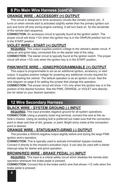
6 Pin Main Wire Harness (cont’d)Orange Wire - Accessory (+) OutputThis circuit is designed to drive accessory circuits like climate control, etc.. Itturns on when remote start is activated (slightly earlier than the primary ignition output)and turns off only during engine cranking. It will turn back on for the remainderof the remote start sequence.CONNECTION: An accessory circuit is typically found at the ignition switch. Theproper circuit will show +12v when the ignition key is in the ON/RUN position but notin the START position.Violet Wire - Start (+) OutputREQUIRED. This output supplies positive voltage to the vehicle’s starter circuit. Ifusing an anti-grind relay, connected this on the starter side of the relay.CONNECTION: The starter circuit is typically found at the ignition switch. The propercircuit will show +12v only when the ignition key is in the START position.Pink/White Wire - Ign#2/Programmable (+) OutputThis output is programmable to act as an additional ignition, accessory, or startoutput. It supplies positive voltage for powering any additional circuits required forremote starting the vehicle. The default operation is as an ignition circuit. See thewire diagram on page 6 for setting the jumper that change this operation.CONNECTION: The proper circuit will show +12v only when the ignition key is in theposition of the desired function. See the PINK, ORANGE, or VIOLET wire descriptionfor detail on your desired operation.12 Wire Secondary HarnessBlack Wire - System Ground (-) InputREQUIRED. This input provides negative ground for all system operations.CONNECTION: Using a properly sized ring terminal, connect this wire to the vehicle’schassis. Using an existing bolt is preferred but make sure that the connectionpoint is clean and free of dirt, grease, or paint. Bright shiny metal at the connectionpoint is desired.Orange Wire - Status/Anti-grind (-) OutputThis provides a 500mA negative output slightly before and during the large PINKignition wire’s operation.CONNECTION: This is typically used to activate immobilizer bypass modules.Connect it directly to the module’s activation input. It can also be used with a starterinterrupt relay for starter anti-grind operation.Brown/Red Wire - Brake Pedal (+) InputREQUIRED. This input is a critical safety circuit which disables the remote startoperation whenever the brake pedal is pressed.CONNECTION: Connect this to the brake switch wire that shows +12 volts when thebrake pedal is pressed.4